Note: Descriptions are shown in the official language in which they were submitted.
CA 02652713 2008-11-18
WO 2008/021604 PCT/US2007/069349
RAPID SYNTHESIS OF TERNARY, BINARY AND
MULTINARY CHALCOGENIDE NANOPARTICLES
RELATED APPLICATIONS
[0001] This application claims priority to U.S. Provisional Patent Application
Serial No. 60/801,963, filed May 19, 2006, the disclosure of which is
expressly
incorporated in its entirety herein by this reference.
TECHNICAL FIELD
[0002] The present invention is related generally to the rapid and economic
preparation of crystalline binary, ternary and/or multinary chalcogenide
nanoparticles,
and particularly nanoparticles of various compositions of Cu, In, Ga, and Se.
BACKGROUND OF THE INVENTION
[0003] CuInSe2 and its related alloys, including CuInS2, CuGaSe2, CuGaS2,
Cu(InXGai_X)Se2 , Cu(InGaj_x)Sz, and Cu(InXGaj_x)(SySeZ_y) where 0<x<1 and
25y<0,
(collectively known as CIGS), are some of the most promising candidates for
photovoltaic applications due to their unique structural and electrical
properties. CIGS
thin film solar cells are highly stable against radiation, which makes them
ideal for space
applications. High efficiency solar cells have been fabricated based on CIGS
absorber
films grown by various techniques, with the highest reported efficiency of
19.2%
reported using vacuum co-evaporation.(') The highest quality CIGS thin films
have been
traditionally fabricated using vacuum co-evaporation, however, the resulting
production
costs of such fabrication processes are typically high, thereby limiting its
usefulness in
large-scale mass production applications. There are also issues associated
with
uniformity of the film for roll-to-roll processing. Thus, there has been a
continuing
effort to develop thin film deposition techniques for large area substrates
using cost
effective techniques.
[0004] To circumvent the limitations of vacuum co-evaporation, several
techniques based on the selenization of metallic or binary precursor layers
and
particulate precursor films have been reported.(2"7) The selenization of pre-
deposited
Cu/In metal precursors on substrates by either H?Se gas or Se vapor is
currently favored
for commercial manufacturing processes. However, these selenization processes
are
1
CA 02652713 2008-11-18
WO 2008/021604 PCT/US2007/069349
complicated and timely, as well as require high operating temperatures,
thereby resulting
in increased processing costs and low production rates. In addition, the
required use of
highly toxic gases during the selenization process (such as H-,Se, for
instance), as well as
the use of high-end equipment to safely maintain the increased temperature
levels,
significantly adds to the fabrication costs associated with these processes.
Although
there are several commercialized processes based on the selenization of
precursor films,
the inherent drawbacks associated with these processes (e.g., high costs,
composition
control and material utilization issues) limit the mass utilization of the
CIGS
photovoltaic cells.
[0005] Other techniques, including electrodeposition,(8) chemical vapor
deposition,(9-11) and spray deposition,(12' ") have also been explored for the
fabrication of
CIGS thin films. These techniques, however, are limited due to low material
utilization,
as well as low crystallinity and small crystalline sizes of the as-synthesized
thin films.
[0006] Recently, nanocrystalline semiconductors have attracted a considerable
amount of attention due to their unique physiochemical properties and
potential
applications in novel optical, electrical, and optoelectrical devices. Several
groups have
demonstrated the use of nanoparticle building blocks for the fabrication of
nanostructured solar cells. For instance, Gur et al. demonstrated the
fabrication of air
stable inorganic solar cells by spin coating thin films of CdTe and CdSe
nanoparticles.(14) Also, previous work on the fabrication of CuInSe2 (CIS) and
Cu(InGa)Se2 (CIGS) thin films using amorphous Cu-In-Se and Cu-In-Ga-Se
nanoparticles, respectively, has been reported by Schulz et al.( 15) However,
the
nanoparticles employed in this study were amorphous and high temperature
annealing
under a selenium environment was required to achieve the desired crystalline
structure.
Thus, CIS and/or CIGS nanoparticles having the desired composition and
crystalline
structures are expected to be ideal candidates for low cost solar cells,
particularly as they
allow the use of low-cost coating techniques, such as spray printing, spin
coating, and
doctor blading. In addition, by using CIS or CIGS nanoparticles with fixed
compositions and crystalline structures, the use of high temperature
selenization
processes under toxic H2Se gas can be minimized or even eliminated.
Furthermore, the
composition of the film could be easily controlled on all scales by
controlling the
composition of the nanoparticles. Composition uniformity allows relatively
large
tolerance in the thickness of the film, such that traditional coating
techniques (such as
spin coating, dip coating, and spray printing) can be employed to fabricate
CIS or CIGS
2
CA 02652713 2008-11-18
WO 2008/021604 PCT/US2007/069349
thin films. All of these advantages will significantly simplify the
manufacturing process
and lower the fabrication cost of photovoltaic devices.
[0007] Consequently, a simple, controlled, and tunable process for the
synthesis of
CIS or CIGS nanoparticles with the right composition and crystalline structure
needs to
be developed. Several techniques have previously been reported in the
literature for the
synthesis of CuInSe2 and related nanoparticles. For instance, Carmalt et al.
presented
the solid state and solution phase metathesis synthesis of copper indium
chalcogenides
using metal halides and sodium chalcogenides as precursor materials.(16) For
the solid-
state metathesis reaction, the reaction was conducted inside a sealed ampoule
and heated
to 500 C for 48 hours to produce single-phase CuInSe2 particles. Although
solid-state
metathesis has been utilized for the synthesis of binary materials, it is
difficult to use for
the synthesis of ternary or multinary materials due to possible phase
segregations. Thus,
solid-state metathesis typically requires an extensive period of time to
ensure the
formation of a ternary phase. The solution phase metathesis reaction has also
been
presented by Carmalt et al. where the same precursors were refluxed in toluene
for 72
hours. The solution phase metathesis reaction allows the use of low
temperature
synthesis; however, the particles produced are amorphous and require high
temperature
annealing at 500 C for 24 hours in order to obtain the desired crystalline
structure.
[0008] Similar solution phase metathesis reactions have also been employed by
Schulz et al. in their synthesis of CIGS nanoparticles.(15) In this case, the
Cu-In-Ga-Se
nanoparticles were prepared by reacting a mixture of Cul, InI3i and GaI3 in
pyridine with
Na2Se in methanol at a reduced temperature and under inert conditions. The
nanoparticles produced in this reaction, however, were also amorphous and high
temperature annealing was required to achieve the desired crystalline
material.
[0009] Another method ("hot injection method") was pioneered by Murray et al.
to
synthesize various metal and semiconductor nanocrystals, particularly those
having
diverse compositions, sizes and shapes.(l7) In a typical `hot injection'
synthesis, organic
ligands are used to passivate the surface of the nanoparticles to prevent
particle
aggregation. Moreover, nanoparticles with monodispersed sizes and shapes can
be
synthesized by controlling the concentration and functional group of the
organic ligands.
[0010] The synthesis of CuInSeZ nanoparticles using the "hot injection
technique"
was first presented by Malik et al. in trioctylphosphine oxide (TOPO) and
trioctylphosphine (TOP) by a two step reaction.(' 8) In this reaction, a TOP
solution of
CuCl and InCI3 was injected into TOPO at 100 C and then followed by a hot
injection of
3
CA 02652713 2008-11-18
WO 2008/021604 PCT/US2007/069349
trioctylphosphine selenide (TOPSe) at an elevated temperature of 330 C to
initiate the
nucleation and growth of nanoparticles. Spherical CuInSe2 nanoparticles of
about 4.5
nm were synthesized according to the authors, and the Powder X-Ray Diffraction
("PXRD") data presented indicated that binary materials such as Cu2Se and
In?03 were
present as by-products.
[0011] In another study relating to the pyrolysis of molecular single source
precursors, the stoichiometry precursor (PPh3)2CuIn(SePh)4 was used in the
synthesis of
a CuInSe-2 nanoparticle using spray pyrolysis.(19) While nanocrystalline
CuInSe?
particles ranging from about 3-30 nm were produced by the thermal
decomposition of
the molecular precursor, the synthesized nanocrystals typically agglomerated
into large
clusters. Moreover, the PXRD data indicated that CuInSe2 nanocrystals were
only
produced at high temperatures (e.g., from about 275 C to about 300 C).
However, no
direct images of the nanocrystals were presented. Some of the drawbacks of
this process
are that the preparation of the molecular precursors could be difficult and
costly, as well
as require low material utilization.
[0012] More recently, Grisaru et al. presented a microwave-assisted synthesis
process of CuInSe2 nanoparticles using CuCI and elemental In and Se as
precursors in
ethylene glycol based solvents.(20) While the reaction time was much faster
applying
microwave heating, the synthesized nanoparticles lacked defined shapes and
sizes, and
generally agglomerated together into large clusters. Furthermore, small
amounts of
Cu2Se were also detected as by-products from the reaction as shown from the
PXRD
data presented by the authors.
[0013] Another process, which was presented by Li et al., involved the
preparation
of CuInSe2 nanowhiskers and nanoparticles using CuC12, InC13, and Se as
reagents in
ethylenediamine and diethylamine, respectively, and particularly using a
solvothermal
route.(21) It was suggested by the authors that amine served as a structure
directing agent
in the solvothermal synthesis. PXRD characterization of the nanoparticles
showed a
clean single phase of chalcopyrite CuInSe2. Jiang et al, also explored the
solvothermal
synthesis of CuInSe2 nanorods and nanoparticles using elemental Cu, In, and
Se.(2')
Chun YG et al. further expanded the synthesis into quatemary Cu(InGa)Se2
nanoparticles by solvothermal reaction of elemental Cu, In, Ga, and Se in
ethylenediamine.(23) However, generally the nanoparticles synthesized using
solvothermal techniques were highly polydispersed. A key feature of these
solvothennal
syntheses is that they are conducted in a closed autoclave and generally
require from
4
CA 02652713 2008-11-18
WO 2008/021604 PCT/US2007/069349
about 15 hours to a few days to perform. The reaction is also conducted at
pressures
much higher than atmospheric pressures and requires pressurized equipment
because of
the low normal boiling temperatures of the solvents used during the synthesis.
For
example, the normal boiling temperature for ethylenediamine and diethylamine
is about
118 C and 55 C, respectively. FIG. 1 shows that ethylenediamine and
diethylamine
have very high vapor pressures over the range of reaction temperatures usually
used in
the solvothermal synthesis. Such equipment and associated handling procedures
add
cost to the final product and are less amenable to very large-scale production
such as is
typically needed for world-scale solar panel manufacturing plants.
[0014] Although several methods have been reported on the synthesis of CuInSe2
nanoparticles, none of the above-mentioned techniques are able to sufficiently
control
the size, shape, crystallinity and/or purity of the nanoparticles.
Furthermore, many of
the above-mentioned techniques typically require long reaction times. Thus, it
is
desirable to develop a fast and efficient process capable of producing
crystalline CIS or
CIGS nanoparticles without resulting impurities or by-products. As such, the
present
teachings are intended to overcome and improve upon these and/or other
shortcomings
currently found within the prior art.
SUMMARY OF THE INVENTION
[0015] The present invention is related generally to the rapid and economic
preparation of crystalline ternary or multinary chalcogenide nanoparticles of
various
compositions of Cu, In, Ga, and Se.
[0016] According to one aspect of the present invention, a fast and efficient
process for synthesizing binary, ternary and/or multinary nanoparticles using
commonly
available precursors at moderate teinperatures and at atmospheric or near
atmospheric
pressures is provided. According to this aspect of the present invention, the
binary,
ternary and/or multinary nanoparticles may be selected from various
combinations of
Cu, In, Ga, Se, and S, and the precursors may include various metal halides,
elemental
metals, elemental chalcogen, as well as chalcogen compounds.
[0017] According to another aspect of the present invention, the synthesis of
the
presently disclosed chalcogenide nanoparticles is accomplished by using the
above-
mentioned precursors in alkylamines, particularly those having normal boiling
temperatures greater than 220 C, or alkyl chain lengths greater than or equal
to about 12
carbons. In certain embodiments, there can be more than one alkyl chain
attached to the
CA 02652713 2008-11-18
WO 2008/021604 PCT/US2007/069349
amine group. In such cases, the total carbon atoms on all the alkyl chains are
equal to or
greater than about 12. The normal boiling temperature (Tb) is defined as the
temperature
at which an alkylamine has a vapor pressure of one atmosphere absolute.
Moreover, the
alkyl tail of the amine may be saturated, unsaturated, branched, or any
combination
thereof.
[0018] According to another aspect of the present invention, a process capable
of
fabricating CIS and CIGS nanoparticles with a controlled stoichiometry and
crystalline
structure for photovoltaic or other non-solar cell applications is provided.
According to
this aspect of the present invention, the relative atomic proportion of Cu,
In, and Se may
not be strictly 1:1:2. Moreover, the photovoltaic activity may be obtained
when the
structure is slightly deficient in Cu. Preparation of such particles for
proper photovoltaic
activity is within the scope of the present teachings. Alternatively, novel
photovoltaic
cells may be prepared by using particles that are slightly rich in Cu.
Synthesis of such
particles is also within the scope of the present invention.
[0019] In yet another aspect of the present invention, a tunable process
capable of
synthesizing CIS and CIGS nanoparticles with various shapes including
nanoparticles,
nanodisks, and nanorings having a size of about 5 nm to about 1000 nm is
provided.
The synthesis of smaller or greater size particles is also within the scope of
the present
teachings.
[0020] In still another exemplary embodiment herein, the preparation of
crystalline
metal chalcogenide nanoparticles is provided. According to this embodiment,
the metal
chalcogenides may include various combinations of Cu, In, Ga, and Se, such as
CuInSe2,
CuGaSe2 and Cu(InXGa1_X)Se2 for example. The composition of the chalcogenide
nanoparticles could be stoichiometric, excessive or deficient in copper.
Moreover, the
composition of the nanoparticles is not limited to the above-mentioned
elements, and the
process described in this description could be adapted for the synthesis of
other
chalcogenide nanoparticles of tellurium or sulfur with various suitable
metals.
[0021] In an alternate embodiment, a method for making crystalline metal
chalcogenide nanoparticles is provided. According to this method, the metal
and
chalcogenide precursor solutions are prepared in organic solvents and
alkylphosphine
and the subsequent solution phase of the precursor is reacted to form the
metal
chalcogenide nanoparticles. The solution phase of the reaction comprises
organic
solvents including saturated, non-saturated or branched alkylamines, and
particularly
alkylamines having a high boiling temperature (Tb>220 C) or a chain length of
12
6
CA 02652713 2008-11-18
WO 2008/021604 PCT/US2007/069349
carbons or greater. For instance, exemplary precursors include various metal
halides,
elemental metals and/or elemental chalcogens. Typically, the reaction is
performed
relatively quickly, whereby considerable amounts of nanoparticles are formed
within
minutes after the constituting precursors are added. To separate the
nanoparticles from
the reaction mixture, solvent and/or anti-solvent may be added to the reaction
mixture,
and then the mixture centrifuged to collect the solid precipitate of the
nanoparticles.
Thereafter, the supernatant can be decanted and the precipitate re-dispersed
in a non-
polar solvent (e.g., hexane and toluene) to form a stable nanoparticle
suspension.
[0022] In further exemplary embodiments herein, the chalcogenide nanoparticles
of the present invention may comprise elemental constituents substitutable
with an
elemental metal or a combination thereof. According to this exemplary
embodiment, the
elemental metals substitutable with the elemental constituents include Ag, Zn,
and Cd.
[0023] According to another exemplary embodiment, a method for synthesizing a
chalcogenide nanoparticle is provided. The method comprises reacting a metal
component with a chalcogen precursor in the presence of an organic solvent
having at
least one of a boiling temperature equal to 220 C or above and a chain length
of about
12 carbon atoms or above.
[0024] In yet another exemplary embodiment, a method for synthesizing
crystalline metal chalcogenide nanoparticles is provided. According to this
exemplary
embodiment, the method comprises preparing a reaction mixture by combining a
metal
precursor solution with a chalcogen precursor solution in the presence of an
organic
solvent, the organic solvent having at least one of a boiling temperature 220
C or above
and a chain length of at least 12 carbon atoms; separating nanoparticles from
the reaction
mixture by adding at least one of a solvent and an anti-solvent to the
mixture; collecting
a solid precipitate of the nanoparticles from the mixture; and re-dispersing
the precipitate
in a non-polar solvent to form a stable nanoparticle suspension.
[0025] In still another exemplary embodiment, a method for synthesizing
crystalline metal chalcogenide nanoparticles is provided in which a metal
component is
reacted with a chalcogen precursor in the presence of an alkylamine solvent
selected
from the group consisting of dodecylamines, tetradecylamines, hexadecylamines,
octadecylamines, oleylamines and trioctylamines. According to this embodiment,
the
chalcogenide nanoparticles comprise at least one of ternary, multinary, and
binary
chalcogenide nanoparticles, the ternary, multinary and binary chalcogenide
nanoparticles
7
CA 02652713 2008-11-18
WO 2008/021604 PCT/US2007/069349
each being formed of a combination of components selected from the group
consisting
of Cu, In, Ga and Se.
[0026] In yet another exemplary embodiment, a method for synthesizing a
chalcogenide nanoparticle is provided. The method comprises reacting a metal
component with a chalcogen precursor in the presence of an organic solvent
near
atmospheric pressure and for a period of from about 5 minutes to about 60
minutes.
[0027] The above-mentioned aspects of the present teachings and the manner of
obtaining them will become more apparent and the teachings will be better
understood
by reference to the following description of the embodiments taken in
conjunction with
the accompanying drawings, wherein:
BRIEF DESCRIPTION OF THE DRAWINGS
[0028] Figure 1 depicts vapor pressures versus temperature curves for
ethylenediamine and diethylamine;
[0029] Figure 2 depicts vapor pressures versus temperature curves for
dodecylamine and tetradecylamine;
[0030] Figure 3 depicts a schematic drawing of an experimental setup in
accordance with the present invention;
[0031] Figure 4 depicts a PXRD pattern of sphalerite CuInSe2 nanoparticles as-
synthesized in oleylamine;
[0032] Figure 5 depicts an FE-SEM image of sphalerite CuInSe2 nanoparticles as-
synthesized in oleylamine;
[0033] Figures 6a and b depict TEM images of sphalerite CuInSe2 nanoparticles
prepared in oleylamine;
[0034] Figure 7 depicts a PXRD pattern of chalcopyrite CuInSe2 nanoparticles
as-
synthesized in oleylamine;
[0035] Figure 8 depicts an FE-SEM image of chalcopyrite CuInSe2 nanoparticles
prepared in oleylamine;
[0036] Figure 9 depicts an UV-VIS absorption spectrum of chalcopyrite CuInSe2
nanoparticles;
[0037] Figure 10 depicts an FE-SEM image of large CuInSe2 nanodisks prepared
in octadecylamine;
8
CA 02652713 2008-11-18
WO 2008/021604 PCT/US2007/069349
[0038] Figures 11 a and b depict TEM images of a CuInSe2 nanodisk and its
corresponding electron diffraction pattern;
[00391 Figure 12 depicts an FE-SEM image of CuInSe2 nanorings as prepared in
oleylamine;
[0040] Figures 13a and b depict TEM images and selected area electron
diffraction
patterns of CuInSe2 nanorings;
[0041] Figure 14 depicts a PXRD pattern of CuGaSe2 nanoparticles as-
synthesized
in oleylamine;
[0042] Figure 15 depicts a PXRD pattern of Cu(Ini_,Ga,,)Se2 nanoparticles as-
synthesized in oleylamine; and
[0043] Figures 16a and b depict TEM images and electron diffraction patterns
of
CdSe nanoparticles as-synthesized in oleylamine.
DETAILED DESCRIPTION
[0044] The embodiments of the present teachings described below are not
intended
to be exhaustive or to limit the teachings to the precise forms disclosed in
the following
detailed description. Rather, the embodiments are chosen and described so that
others
skilled in the art may appreciate and understand the principles and practices
of the
present teachings.
[0045] The present invention details steps for the synthesis of high-quality
crystalline metal chalcogenide nanoparticles including Cu, In, Ga, and Se. The
synthesis
involves reacting metal precursors with chalcogen precursors in organic
solvents to form
the corresponding chalcogenide nanoparticles. Exemplary metal precursors
include, for
instance, elemental metals or metal halides. In an exemplary embodiment, the
illustrative precursors are metal chlorides such as CuCl, InC13 and GaC13.
Other
exemplary examples of metal halides include iodides, bromides, etc. Moreover,
the
chalcogen precursors may be elemental or compounds of elements, such as those
found
within group 16 of the periodic table, for instance S, Se, and Te. The process
that is the
focus of this exemplary embodiment has a number of advantages over other
reported
synthesis processes that use similar materials. For instance, unlike many
traditional
processes, the present processes have a fast reaction time, are able to
synthesize at
moderate temperatures and/or near atmospheric pressure, use commonly available
precursor materials, as well as are able to synthesize ternary and multinary
crystalline
chalcogenide nanoparticles.
9
CA 02652713 2008-11-18
WO 2008/021604 PCT/US2007/069349
[00461 The disclosed methods are primarily focused on describing the synthesis
of
CuInSe2 and CuGaSe2 nanoparticles. It should be understood, however, that for
those
skilled in the art, the same process may also be applied to the synthesis of
any
combination of nanoparticles such as, for example, Cu(Inl_XGaX)Se2,
Cu1_XInSe2, Cu1_
y(Inl_XGaX)Se2, as well as the synthesis of various binary or multinary
chalcogenides,
such as Cu, In, or Ga with Se. Exemplary binary compounds in accordance with
the
present teachings include, but are not limited to, CuSe, Cu2_XSe, GaSe,
Ga~Se3, InSe,
In2Se3, CuSe2), GaSe2 and InSez. It also should be understood that the present
invention
can be practiced using any suitable combination of metal or various
combinations of
metals. Moreover, it should also be understood and appreciated herein that any
disclosed ratios may be substituted for the Cu, In, and Ga components, as well
as the S
and Te components may be substituted for the Se components. In further
exemplary
embodiments disclosed herein, the chalcogenide nanoparticles may comprise
elemental
constituents substitutable with an elemental metal or a combination thereof.
According
to this exemplary embodiment, the elemental metals substitutable with the
elemental
constituents include Ag, Zn, and Cd. For convenience, elements discussed in
the
embodiments of the present teachings are typically represented with their
commonly
accepted chemical symbols, including copper (Cu), indium (In), gallium (Ga),
selenium
(Se), silver (Ag), zinc (Zn) and cadmium (Cd).
[0047] Suitable organic solvents useful in accordance with the present
teachings
include any alkylamine having a normal boiling temperature greater or equal to
about
220 C and/or having a carbon chain length of about 12 or above. The alkyl tail
of the
amine may be saturated, unsaturated or branched. Besides monoalkylamines,
dialkyl
and trialkylamines may be used. In such cases, the total number of carbon
atoms in the
alkylamine molecule (including all the alkyl chains) is greater than or equal
to about 12.
The purpose of the alkylamine is to provide a medium for the reaction and to
assist in
minimizing or preventing agglomeration of the nanoparticles. Without wishing
to be
tied to theory, it is believed that the alkylamine provides a coordinating
media that
covers the surface of nanoparticles and keeps them from agglomerating.
However, this
expectation should not be construed as limiting this description. Some
specific
examples of suitable organic solvents include dodecylamine, tetradecylamine,
hexadecylamine, octadecylamine, oleylamine, and trioctylamine.
[0048] FIG. 2 depicts vapor pressure curves for dodecylamine and
tetradecylamine. As can be seen from FIG. 2, the exhibited vapor pressures of
CA 02652713 2008-11-18
WO 2008/021604 PCT/US2007/069349
dodecylamine and tetradecylamine are much lower than those exhibited for
ethylenediamine and diethylamine (see FIG. 1). While the vapor pressures of
dodecylamine and tetradecylamine are lower than those exhibited for
ethylenediamine
and diethylamine, the vapor pressures of the even longer chain alkylamines are
expected
to be even lower. More particularly, the use of such long chain alkylamines
allows the
reaction to be conducted at near atmospheric pressures and at temperatures
greater than
or equal to about 220 C. At higher reaction temperatures, a judicious choice
of
alkylamine will keep the reaction pressure close to atmospheric pressure,
which is
desirable in certain specific embodiments. However, in other specific
embodiments, the
reaction may be run at a pressure slightly higher than atmospheric pressure.
In any
event, it has been determined that having the reaction pressure within a few
psi of
atmospheric pressure is an optimal operating condition in accordance with the
present
teachings. It should be understood, however, that the reaction pressure may be
as high
as six (6) atmospheres absolute in certain embodiments.
[0049] Preventing oxygen from being present in the reaction medium during the
synthesis of the chalcogenide nanoparticles, particularly due to the possible
formation of
metal oxides, is an aspect that should also be considered upon performing the
processes
of the present teachings. More particularly, if metal oxides are formed,
efforts should be
made to avoid introducing oxygen into the system, including even incidental
amounts of
oxygen within the system. As will be understood and appreciated by those of
ordinary
skill in the art, special techniques and equipment are available to achieve an
oxygen-free
atmosphere. As such, the precursor can be prepared in a solution in an oxygen-
free
atmosphere or inside a glove box, for instance, by using a Schlenk line or
vacuum line
connected to a condenser and round bottom flask. If the introduction of oxygen
into the
system is unavoidable, however, for example during the addition of solvents or
precursor
solution to the reaction flask, it may be necessary to degas and/or purge the
system with
inert gas (e.g., N2, Ar, or He) to remove the oxygen before proceeding to
further steps.
Such techniques (as briefly described above) are well known and within the
skill of the
ordinary artisan. Although it may be useful to conduct the present reactions
under
oxygen-free atmospheric conditions, such an oxygen-free environment is not
required
herein and should not be viewed as limiting the scope of the present
teachings.
[0050] FIG. 3 depicts a schematic of an exemplary experimental apparatus 300
useful in accordance with the present teachings. According to this exemplary
embodiment, a round-bottom flask 305 having three necks is used. One of the
necks 302
11
CA 02652713 2008-11-18
WO 2008/021604 PCT/US2007/069349
is connected to a thermometer or thermocouple 304, which is used to monitor
the
temperature of the reaction within the reaction flask 305, while a second neck
306 is
connected to a condenser 308. The condenser 308 is further connected to a
Schlenk line
(not shown), i.e., a vacuum gas manifold, which connects to a vacuum pump and
an inert
gas supply. This arrangement allows the connected apparatus to be purged with
inert
gas by switching between vacuum and inert gas flows. The purging is done by
switching the system to a vacuum mode for about 5-15 minutes to remove the gas
inside
the flask 305 and then switching back to an inert gas flow to backfill the
flask. The
inert gas backfills the flask 305 because the pressure inside of the flask is
lower from the
vacuuming process. A third neck 310 is usually sealed with a rubber stopper
and serves
as an injection port 312 for the addition of precursors and solvents using a
syringe 314.
A heating mantle or oil/sand bath can be used to heat the flask. A magnetic
stirrer 316 is
usually placed inside the flask 305 to keep the reaction mixture well mixed.
[0051] The crystalline chalcogenide nanoparticles of the present teachings are
formed by preparing corresponding metal and chalcogen precursor solutions in
an
alkylamine or alkylphosphine solvent. The metal precursor solution is then
added to a
fixed amount of alkylamine solvent, which is typically about 1-5 times greater
than that
of the metal precursor. The metal precursor is degassed and purged with inert
gas at a
suitable temperature, typically ranging from about room temperature (e.g.,
about 20 C to
about 25 C or about 68 F to about 77 F) to an elevated temperature. Suitable
elevated
temperatures in which the alkylamine solvent is degassed and purged with inert
gas in
accordance with the present teachings include any suitable temperature higher
than the
room temperature, and is generally higher than about 100 C or at the boiling
temperature
of the solvent under the vacuum condition of degassing.
[0052] After the addition of the metal precursor solutions, the system is then
purged with an inert gas typically about three to five times to remove any
incidental
oxygen that may have been introduced during the addition of the precursors.
Next, a
stoichiometric or near stoichiometric amount of chalcogen precursors may be
added to
the solution, and then its temperature increased to about 220 C or above to
form the
corresponding chalcogenide nanoparticle. Alternatively, the chalcogen
precursors may
be added at the final reaction temperature of 220 C or above, to form the
corresponding
metal chalcogenide nanoparticles. In the case of CIS, the color of the
solution turns dark
immediately after the injection of the selenium precursor, which indicates the
formation
of nanoparticles. If the temperature is sufficiently high, the reaction is
typically
12
CA 02652713 2008-11-18
WO 2008/021604 PCT/US2007/069349
completed in less than an hour and usually within five minutes after the
injection of the
selenium precursor. After the reaction, the solution is cooled down to room
temperature
by either removing the heating element or quenching the solution by adding a
room
temperature solvent (alkylamine). Next, an amount of a solvent (e.g., hexane
or toluene)
and a miscible anti-solvent (e.g., ethanol or methanol) is added to the
reaction mixture
and the nanoparticles may be collected by centrifuging. The amount of solvent
and anti-
solvent added is usually near the volume of the synthesized reaction mixture.
After
centrifuging, the particles may be obtained by decanting the supernatant.
[0053] In one embodiment of the present invention, the shape of the
chalcogenide
nanoparticles can be controlled by varying the solvents used in the synthesis
method.
For the synthesis of near-isotropic chalcogenide nanoparticles, metal and
chalcogen
precursors are dissolved in alkylamine and reacted without the addition of any
other
solvents or capping agents at a temperature of about 220 C or above to produce
the
corresponding chalcogenide nanoparticles. During the preparation of the metal
halide
precursor solution, the temperature may be increased to about 100 C to enhance
the
solubility of the metal halides. To synthesize disk-shaped chalcogenide
nanoparticles,
the metal and chalcogen precursors are dissolved in trioctylphosphine (TOP),
and are
reacted in octadecylamine at a temperature about 220 C or above. To synthesize
ring-
shaped chalcogenide nanoparticles, the metal and chalcogen precursors are
dissolved in
trioctylphosphine (TOP), and are reacted in oleylamine at a temperature about
220 C or
above.
[0054] It is possible to synthesize the ring and disk shaped nanoparticles by
reacting chalcogen precursors dissolved in TOP with metal precursors dissolved
in
alkylamines. It is also possible to direct the shape of the nanoparticles by
independently
adding TOP into a reaction. It should be understood that the above-mentioned
methods
for preparing the precursor solutions are illustrative only and should not be
construed as
limiting the scope of the present invention, particularly as numerous
modifications and
changes can be readily made by those skilled within the art. For example, the
metal or
chalcogen precursors may be dissolved in alkylamines that are different from
the
alkylamine in which the reaction is conducted. An example may be the use of
alkylamines having low boiling temperatures for dissolving the precursor.
Moreover, it
should also be understood and appreciated herein that the order for adding the
constituting metal and chalcogen precursors, as well as the associated
temperature
needed to conduct the reaction, can be varied in the synthesis method without
straying
13
CA 02652713 2008-11-18
WO 2008/021604 PCT/US2007/069349
from the scope of the present teachings. For example, the order of adding the
constituting precursors may be altered and/or all of the constituting
precursors may be
added at once at a desirable temperature. In addition, all or part of the
constituting
precursors may be added at low temperatures, such as for instance between
about 110 C
and about 220 C, or at a final reaction temperature, generally above about 220
C.
[0055] An advantage of the presently disclosed methods is the improved quality
of
the as-synthesized chalcogenide nanoparticles. As mentioned above, the
nanoparticles
synthesized by other reported techniques generally have small particles, large
clusters of
agglomerated nanoparticles, lack crystalline structures, impurities or by-
products and/or
require high pressures. However, the chalcogenide nanoparticles prepared as
described
in this disclosure include crystalline particles having desirable
compositions.
Furthermore, the nanoparticles form stable dispersions within the non-polar
solvents.
[0056] Another advantage of the presently disclosed methods is the simplicity
of
the synthesis process. More particularly, the disclosed reaction is very fast,
such that the
crystalline chalcogenide nanoparticles are formed within a few minutes after
the
constituting precursors are added. In addition, the synthesis of the multinary
chalcogenide nanoparticles is performed at a moderate temperature near
atmospheric
pressure. Furthermore, the precursors used for the synthesis of the
chalcogenide
nanoparticles are commonly available. As such, various metal halides or
elemental
precursors can be used for the present teachings. Lastly, the equipment needed
for the
synthesis methods is commonly available - i.e., special equipment is not
needed to
achieve high temperatures and pressures.
[0057] Advantages and improvements of the methods of the present invention are
demonstrated in the following examples. These examples are illustrative only
and are
not intended to limit or preclude other embodiments of the present invention.
[0058] The following examples demonstrate the practice and utility of the
present
invention but are not to be construed as limiting its scope. Any suitable
laboratory
equipment known to those skilled in the art can be utilized to synthesize the
nanoparticles and analyze its properties thereof. In the following examples,
transmission
electron microscopy (TEM) was performed using a JEOL JEM 2000 FX; field
emission
scanning electron microscopy (FE-SEM) was performed using a Hitachi S4800;
powder
X-ray diffraction (PXRD) was performed using a Scintag X2 Diffraction System;
inductively coupled plasma mass spectroscopy (ICPMS) was performed using a
Thermo
14
CA 02652713 2008-11-18
WO 2008/021604 PCT/US2007/069349
Jarrell Ash AtomScan 16, and energy dispersive X-ray spectroscopy (EDX) was
performed using an Oxford Inca 250 EDS system built on a FEI Nova NanoSEM.
EXAMPLE 1:
[0059] CuInSe2 nanoparticles were synthesized using oleylamine as the only
solvent. It is believed that the amines may act as surfactants or stabilizers
during the
synthesis of the nanoparticles even though the present invention is not bound
by this
conjecture. CuInSe2 ) nanoparticles were synthesized by reacting CuCI, InC13,
and Se in
oleylamine at an elevated temperature of about 220 C under an inert
atmosphere. All
manipulations were performed using standard air-free techniques utilizing a
Schlenk line
or glove box. According to the principles of this experimental procedure, 6 ml
of
oleylamine, 2.5 ml of 0.2 molar solution of CuCI in oleylamine, and 2.5 ml of
0.2 molar
solution of InC13 in oleylamine were added to a 25 ml three-neck round bottom
flask
connected to a Schlenk line apparatus as shown in FIG. 3. During the
preparation of the
CuCI precursor solution, the temperature was increased to about 100 C to
enhance the
solubility of CuCI. The contents in the flask were heated to 130 C and purged
with
argon three times by repeated cycles of vacuuming and back-filling with inert
gas, and
then degassed at 130 C for 30 minutes. Next, the temperature of the reaction
mixture
was raised to 285 C, and 1 ml of 1 molar Se powder in oleylamine was rapidly
injected
into the reaction mixture. After injection, the temperature was dropped to
approximately
280 C, and the color of the solution started to turn dark. The temperature was
held at
280 C for 30 minutes until the reaction was completed. After the reaction, the
mixture
was allowed to cool to 60 C and the non-polar solvent hexane was added to
disperse the
particles. The miscible anti-solvent ethanol was then added to flocculate the
particles.
The particles were then collected by centrifuging at 10000 RPM for 10 minutes.
The
dark precipitate was then redispersed in a non-polar solvent to form a stable
dispersion.
[0060] The CuInSe2 nanoparticles were characterized using a number of
techniques. For instance, the size and morphology of the as-synthesized
CuInSe2
nanoparticles were characterized using FE-SEM and TEM. The crystalline
structure of
the CuInSe2 nanoparticles were determined using PXRD, while the composition of
the
nanoparticles were determined using EDX. For characterization purposes, the
nanoparticulate suspension was washed using a hexane and ethanol mixture (1:1
ratio)
and centrifuged to remove any residual solvent. The precipitate was then
redispersed in
toluene and drop-cast on appropriate substrates.
CA 02652713 2008-11-18
WO 2008/021604 PCT/US2007/069349
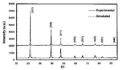
[0061] A typical X-ray diffraction pattern of the as-prepared sphalerite
CuInSe2
nanoparticles synthesized in oleylamine is shown in FIG. 4. The major
diffraction peaks
observed at 26.67, 43.24, 52.42, 65.38, 70.92, 81.42, 87.58, and 97.72 degrees
(20) can
be indexed to the (111), (200), (311), (400), (331), (422), (511), and (440)
planes of the
CulnSe-) sphalerite crystal structure, respectively. A simulated diffraction
pattern of the
sphalerite structure is also shown in FIG. 4 as dashed lines. The simulated
pattern
agrees very well with the experientially observed diffraction pattern.
Furthermore, the
unit cell size calculated from the diffraction data corresponds to a = 5.786
and c =
11.571, and the corresponding c/2a ratio of 1.000, which does not show any
tetragonal
distortion, is an indication of the sphalerite phase. The crystalline size
calculated using
the Scherrer equation corresponds to approximately 35 run.
[0062] The morphology of the sphalerite CuInSe2 nanoparticles was then
examined using FE-SEM. FE-SEM was performed with the samples prepared by
dropping a dilute solution of the nanoparticles in the non-polar solvent
hexane on a
molybdenum foil conducting substrate and left to dry in air or under vacuum.
[0063] FIG. 5 shows a typical FE-SEM image of the nanoparticles synthesized in
oleylamine. The nanoparticles appeared to be isotropic in shapes and had an
average
size of about 40 nm, which corresponds to the crystalline size calculated from
the PXRD
data.
[0064] Further characterization of the nanoparticles using TEM was performed
with the samples prepared by drop casting a dilute solution of the
nanoparticles in non-
polar solvent on a carbon film coated TEM grid. FIG. 6a depicts a large area
micrograph of the as-synthesized CuInSe2 nanoparticles with the inset showing
the
corresponding selected area electron diffraction pattern. The nanoparticles
appear to be
slightly polydispersed in both size and morphology, which corresponds well
with the
observations from the FE-SEM image. FIG. 6b shows a higher magnification image
of
the saine nanoparticles and clearly illustrates that the nanoparticles are
individually
separated from each other with no signs of agglomeration. Composition analysis
using
ICPMS for the CuInSe2 nanorings synthesized in oleylamine showed an overall
Cu:In:Se
ratio of 1.00:1.021:1.945 which is very close to a stoichiometric ratio.
Further analysis
using EDX shows a Cu/In ratio of approximately 1, which is consistent with the
results
from ICPMS.
16
CA 02652713 2008-11-18
WO 2008/021604 PCT/US2007/069349
EXAMPLE 2:
[0065] Chalcopyrite CuInSe2 nanoparticles were synthesized using oleylamine as
the only solvent. It is believed that the amines may act as surfactants or
stabilizers
during the synthesis of the nanoparticles even though the present invention is
not bound
by this conjecture. 3 ml of oleylamine was added to a 25 ml three-neck round
bottom
flask connected to a Schlenk line apparatus as shown in FIG. 3. The contents
in the
flask were then heated to 130 C and purged with argon tliree times by repeated
cycles of
vacuuming and back-filling with inert gas, and then degassed at 130 C for 30
minutes.
Next, 2.5 ml of 0.2 M CuCI in oleylamine, 2.5 ml of 0.2 molar InC13 in
oleylamine, and
4 ml of 0.25 molar Se powder in oleylamine were added to the reaction flask.
After
adding the precursors and purging the mixture with inert gas for a couple
times, the
temperature of the mixture was slowly raised up to 265 C, which took about 1
hour to
achieve. The reaction was then held at 265 C for 1 hour to complete the
process. After
the reaction, the mixture was then allowed to cool to 60 C and the non-polar
solvent
hexane was added to disperse the particles. The miscible anti-solvent ethanol
was then
added to flocculate the particles. The particles were then collected by
centrifuging at
10000 RPM for 10 minutes. The dark precipitate was then redispersed in a non-
polar
solvent to form a stable dispersion.
[0066] FIG. 7 depicts a typical powder PXRD pattern of the as-synthesized
chalcopyrite CIS nanocrystals. The diffraction pattern agrees very well with
the
reference JCPD data (PDF card # 40-1487) for chalcopyrite CuInSe-). The
crystalline
size of the nanocrystals calculated using Scherrer's equation based on the
(112) peak is
45 nm. The major diffraction peaks observed at 26.653, 44.216, 52.394, 64.357,
70.896,
81.381, 87.524, and 97.630 degree (20) can be indexed to the (112),
(204)/(220),
(116)/(312), (008)/(400), (316)/(332), (228)/(424), (336)/(512), and
(408)/(440) of the
tetragonal chalcopyrite crystal structure, respectively. Furthermore, the
minor peaks at
17.142 , 27.741 , and 35.551 corresponding to the (101), (103), and (211)
peaks
respectively are unique to the chalcopyrite structure, as shown in the inset
of FIG. 7.
The lattice constants calculated from the chalcopyrite diffraction data were a
= 5.787
0.003 A and c = 11.617 0.001 A, with the c/2a ratio of 1.004 0.001 showing
the
characteristic tetragonal distortion of the chalcopyrite structure. A
simulated PXRD
pattern of the chalcopyrite is also shown in FIG. 7 as dashed line in trace b.
The
17
CA 02652713 2008-11-18
WO 2008/021604 PCT/US2007/069349
simulated X-ray diffraction pattern of the chalcopyrite structure also agrees
very well
with the experimental observed diffraction pattern.
[00671 FIG. 8 depicts the FE-SEM images of the as-synthesized chalcopyrite CIS
nanocrystals respectively. The size of the chalcopyrite nanoparticles ranges
from about
50 nm for the isotropic nanoparticles and hundreds of nanometers for the
nanodisks.
Further characterization of the chalcopyrite CIS nanoparticles using TEM was
then
performed.
[00681 FIG. 9 shows the UV-VIS absorption spectrum of the chalcopyrite
nanocrystals. The bandgap energy of the CIS nanocrystals was determined using
the
direct bandgap method by plotting absorbance squared versus energy and
extrapolating
to zero, inset of FIG. 9. The bandgap of the nanocrystals was determined to be
1.06 0.02 eV, which is in good agreement with the reported value of 1.04 eV
for
chalcopyrite CuInSe2. The composition of the chalcopyrite nanoparticles was
analyzed
using EDX with statistical exaininations of a large number of different areas
of CIS
nanoparticles. The average composition and standard deviations of the
chalcopyrite CIS
nanoparticles was determined to be Cu0.99t0.11In1.02t0.07Se2, which is very
close to
stoichiometric CuInSe2.
EXAMPLE 3:
[0069J According to this example, CuInSe2 nanoparticles were synthesized into
the
shape of nanodisks. To achieve this, metal and chalcogen precursor solutions
were
prepared by dissolving the corresponding metal halides and Se in
trioctylphosphine
(TOP) where all of the precursors were soluble at room temperature.
Specifically, 7.25
grams of octadecylamine was added to a 25 ml three-neck round bottom flask
connected
to a Schlenk line. The contents in the flask were degassed for 1 hour at 130 C
under
vacuum, and then purged with argon. Next, 0.1 ml of 1 molar solution of CuCl
in TOP
was injected into the flask and purged with argon. Then, 0.1 ml of I molar
solution of
InCl3 in TOP was injected into the flask and purged again with argon. Next,
the content
of the flask was heated to 285 C and 0.2 ml of 1 molar TOPSe was swiftly
injected into
the reaction mixture. After injection, the color of the solution started to
turn dark within
30 seconds after injection, thereby indicating the formation of nanoparticles.
The
temperature was held at 280 C for 30 minutes for the reaction to complete.
After the
reaction, the mixture was allowed to cool to 60 C and hexane and ethanol,
18 1
CA 02652713 2008-11-18
WO 2008/021604 PCT/US2007/069349
approximately 15m1 each, were added to precipitate the nanoparticles. The
precipitate
was collected by centrifuging at 10000 RPM for 10 minutes. The dark
precipitate was
then redispersed in a non-polar solvent to form a stable dispersion.
[0070] The CuInSe2 nanodisks were characterized using the same techniques as
the CuInSe2 nanoparticles as described in Example 1. FIG. 10 shows an FE-SEM
image
of the CuInSe2 nanodisks as-synthesized in octadecylamine. The image shows
that all of
the particles are highly faceted with a majority having well faceted hexagonal
nanodisk
structures. The size of the nanodisks is in the order of 200 nm, which is
significantly
larger than the CuInSe2 nanoparticles described in Example 1.
[0071] A TEM image of a single hexagonal CuInSe2 nanodisk is shown in FIG.
Ila with its corresponding selected area diffraction pattern shown in FIG.
11b. The
electron diffraction shows the hexagonal array of diffraction dots of the
CuInSe2 crystal,
which indicates the nanodisk is of a single crystalline structure.
EXAMPLE 4:
[0072] According to this example, CuInSe2 nanoparticles were synthesized into
the
shape of nanorings using a procedure similar to the preparation of the CuInSe2
nanodisks
of Example 3, however, oleylamine was used as the solvent instead of
octadecylamine.
Specifically, 8.75 ml of oleylamine was added to a 25 ml three-neck round
bottom flask
connected to a Schlenk line. The contents in the flask were degassed for 1
hour at 130 C
under vacuum, and then purged with argon. Next, 0.1 ml of 1 molar solution of
CuC1 in
TOP was injected into the flask and purged with argon. Then, 0.1 ml of 1 molar
solution
of InC13 in TOP was injected into the flask and purged again with argon. Next,
the
contents of the flask were heated to 285 C and 0.2 ml of I molar TOPSe was
swiftly
injected into the reaction mixture. After injection, the color of the solution
started to
turn dark within 30 seconds after injection indicating the formation of
nanoparticles.
The temperature was held at 280 C for 30 minutes for the reaction to complete.
After
the reaction, the mixture was allowed to cool to 60 C and hexane and ethanol
were
added to precipitate the nanoparticles. The precipitate was collected by
centrifuging at
10000 RPM for 10 minutes. The dark precipitate was then redispersed in a non-
polar
solvent to form a stable dispersion.
[0073] The CuInSe2 nanorings were characterized using the same techniques as
described in the previous examples. FIG. 12 shows a FE-SEM image of the
CuInSe?
19
CA 02652713 2008-11-18
WO 2008/021604 PCT/US2007/069349
nanoparticles as-synthesized in oleylamine showing the nanoring structure. It
is
interesting to note that the nanorings self-assembled face-to-face on their
edge into long
chains, thereby showing that the nanoparticles have a 2D ring structure. The
self-
assembly was a result of the strong Van der Waal attraction between the faces
of the
nanorings.
[0074] TEM images of the as-synthesized CuInSe2 nanorings are shown in FIG 13.
FIG. 13a shows a large area TEM micrograph of the CuInSe2 nanorings as-
synthesized
in oleylamine. The nanorings have hexagonal facets and are relatively
monodispersed in
both size and shape with an average outer diaineter of about 30 nm and an
inner
diameter of about 5 nm. Selected area electron diffraction patterns of the
nanorings are
shown in the inset of FIG. 13a, thereby indicating that the nanorings are
crystalline. A
high magnification TEM micrograph of the CuInSe2 nanorings is shown in FIG.
13b,
which further illustrates the unique CuInSe2 nanorings. Electron diffraction
for a single
nanoring is shown in the inset of FIG. 13b. The hexagonal arrays of
diffraction dots are
similar to the diffraction pattern observed for the nanodisks, thereby
indicating that the
nanorings are of single crystalline structure.
EXAMPLE 5:
[0075] According to this example, CuGaSe2 nanoparticles were synthesized using
a procedure similar to the synthesis of the CuInSe2 nanoparticles of Exainple
1,
however, GaC13 was used instead of InC13. According to this example, 15 ml of
oleylamine, 2.5 ml of 0.2 molar solution of CuCI in oleylamine, and 2.5 ml of
0.2 molar
solution of GaC13 in oleylamine were added to a 100 ml three-neck round bottom
flask
connected to a Schlenk line. During the preparation of the CuCl and GaC13
precursor
solutions, the temperature may be increased to about 100 C to enhance the
solubility of
the CuCI and GaC13. The contents in the flask were heated to 130 C, purged
with argon
three times, and then degassed at 130 C for 30 minutes. Next, the temperature
of the
reaction mixture was raised to 285 C, and 1 ml of 1 molar Se powder in
oleylamine was
rapidly injected into the reaction mixture. After injection, the temperature
dropped to
about 280 C and the color of the solution started to turn dark immediately
indicating the
formation of nanoparticles. The temperature was held at 280 C for 30 minutes
for the
reaction to complete. After the reaction, the mixture was allowed to cool to
60 C and
hexane and ethanol were added to precipitate the nanoparticles. The
precipitate was
CA 02652713 2008-11-18
WO 2008/021604 PCT/US2007/069349
collected by centrifuging at 10000 RPM for 10 minutes. The dark precipitate
was then
redispersed in a non-polar solvent to form a stable dispersion.
[00761 FIG. 14 shows a typical X-ray diffraction pattern of the as-prepared
CuGaSe? nanoparticles as-synthesized in oleylamine. The major diffraction
peaks
observed at 27.706, 46.302, 54.454, and 66.906 degree (20) can be indexed to
the (112),
(204)/(220), (116)/(312), and (008)/(400) planes of the CuGaSe2 crystal
structure
respectively, indicating the CGS nanocrystals are also crystalline. The
crystalline size
calculated using the Scherrer equation corresponds to approximately 33 nm. The
diffraction pattern does not show any impurity or by-product peaks, thereby
indicating
that pure CuGaSe2 ) was formed. The composition of the nanoparticles was
analyzed
using EDX where the ratio of Cu/Ga was approximately 0.9.
EXAMPLE 6:
[0077] According to this example, Cu(InGa)Se2 ) nanoparticles were synthesized
using a procedure similar to that used to synthesize the CuInSe2 nanoparticles
in
Example 1, however, the desired amount of GaC13 and InCl3 was such that the
total ratio
of Cu/(In+Ga) was approximately 1. Specifically, 15 ml of oleylamine, 2.5 ml
of 0.2
molar solution of CuCI in oleylamine, and 2 ml of 0.2 molar solution of InC13
in
oleylamine, and 0.5 ml of 0.2 molar GaC13 in oleylamine were added to a 100 ml
three-
neck round bottom flask connected to a Schlenk line. The contents in the flask
were
heated to 130 C, purged with argon three times, and then degassed at 130 C for
30
minutes. Next, the temperature of the reaction mixture was raised to 285 C,
and 1 ml of
1 molar Se powder in oleylamine was rapidly injected into the reaction
mixture. After
injection, the temperature dropped to about 280 C and the color of the
solution started to
turn dark immediately. The temperature was held at 280 C for 30 minutes for
the
reaction to complete. After the reaction, the mixture was allowed to cool to
60 C and
hexane and ethanol were added to precipitate the nanoparticles. The
precipitate was then
collected by centrifuging at 10000 RPM for 10 minutes.
[00781 FIG. 15 depicts the X-ray diffraction patterns of CuInSe2, Cu(InGa)Sez,
and
CuGaSe2 nanoparticles as-synthesized in oleylamine. The diffraction peaks of
the
Cu(InGa)Se2 nanoparticles resembles that of the pattern shown in FIG. 4, and
particularly wherein the peak positions are shifted slightly to the right. The
inset shows
the enlarged view of the (112) peak of the respective nanoparticles and
clearly indicates
21
CA 02652713 2008-11-18
WO 2008/021604 PCT/US2007/069349
the right shift of the peak due to the incorporation of gallium in the crystal
structure.
Since gallium's atomic size is smaller than that of indium, the diffraction
peaks are
expected to shift to the right as observed in experimental data. The
composition of the
CIGS nanoparticles was analyzed using EDX where the overall ratio of
Ga/(Ga+In) was
approximately 0.11 and the ratio of Cu/(Ga+In) was approximately 0.9.
EXAMPLE 7:
[0079] According to this example, CdSe nanoparticles were synthesized using a
procedure similar to that used to synthesize the CuInSe2 nanoparticles in
Example 1,
however, CdC12 was used as the only source of metal precursor. Specifically,
5.5 ml of
oleylamine, 2.5 ml of 0.2 molar solution of CdC12 in oleylamine were added to
a 25 ml
three-neck round bottom flask connected to a Schlenk line. The contents in the
flask
were heated to 130 C, purged with argon three times, and then degassed at 130
C for 30
minutes. Next, the temperature of the reaction mixture was raised to 315 C,
and 4 ml of
0.25 molar Se powder in oleylamine was rapidly injected into the reaction
mixture.
After injection, the temperature dropped to about 275 C and. The temperature
was held
at 275 C for 30 minutes for the reaction to complete. After the reaction, the
mixture was
allowed to cool to 60 C and hexane and ethanol were added to precipitate the
nanoparticles. The precipitate was then collected by centrifuging at 10000 RPM
for 10
minutes.
[0080] TEM analysis of the as-synthesized CdSe nanoparticles is shown in FIG
16.
FIG. 16a shows a large area TEM micrograph of the CdSe nanoparticles as-
synthesized
in oleylamine. The CdSe nanoparticles are highly faceted and rectangular.
Selected
area electron diffraction patterns of the nanoparticles are shown in the inset
of FIG. 16a,
thereby indicating that the CdSe nanoparticles are crystalline. Higher
magnification of
the CdSe nanoparticles is shown in Figure 16b to further illustrate their
unique shape and
highly faceted nature.
[0081] The above examples show that chalcogenide nanoparticles in various
shapes and sizes can be synthesized in accordance with the presently disclosed
teachings. The exemplary examples provided herein depict a number of
illustrative
shapes and sizes for the nanoparticles, and it is to be understood that the
current process
may be utilized to synthesize nanoparticles of other shapes and sizes without
straying
from the scope of the present teachings. Moreover, the stoichiometry and
composition
22
CA 02652713 2008-11-18
WO 2008/021604 PCT/US2007/069349
of the chalcogenide nanoparticles can also be varied as well. While the
precursor
solutions used to synthesize the various chalcogenide nanoparticles within the
illustrative examples were represented in stoichiometric amounts, it should be
understood that this should not be interpreted as limiting the scope of the
present
invention. Rather, those skilled in the art will readily recognize that
various other
amounts of metal and chalcogen precursors can be used herein and at different
ratios
without straying from the presently disclosed teachings. For example, excess
chalcogen
precursors could be added to drop the reaction temperature to separate the
nucleation
and growth stages and to focus the size distribution of the nanoparticles. In
addition,
through examples the present inventors have shown that in addition to various
chalcogenide nanoparticles of selenium, analogous particles of other
chalcogens (e.g.,
sulfur and tellurium) could also be prepared in accordance with the presently
disclosed
teachings. As such, the present invention is not intended to be limited
herein.
[0082] While an exemplary embodiment incorporating the principles of the
present
invention has been disclosed hereinabove, the present invention is not limited
to the
disclosed embodiments. Instead, this application is intended to cover any
variations,
uses, or adaptations of the invention using its general principles. Further,
this
application is intended to cover such departures from the present disclosure
as come
within known or customary practice in the art to which this invention pertains
and which
fall within the limits of the appended claims.
23
CA 02652713 2008-11-18
WO 2008/021604 PCT/US2007/069349
References
The following are incorporated herein by reference in their entirety:
l. Ramanathan K, Contreras MA, Perkins CL, Asher S, Hasoon FS, et al. 2003.
Progress in Photovoltaics 11: 225-30
2. Schulz DL, Curtis CJ, Flitton RA, Wiesner H, Keane J, et al. 1998. Journal
of'
Electronic Materials 27: 433-7
3. Eberspacher C, Fredric C, Pauls K, Serra J. 2001. Thin Solid Films 387: 18-
22
4. Adurodija FO SJ, Kim SD, Kwon SH, Kim SK, Yoon KH, Ahn BT. 1999.
5. Hermann AM, Mansour M, Badri V, Pinkhasov B, Gonzales C, et al. 2000. Thin
Solid Films 361: 74-8
6. Kaelin M, Rudmann D, Kurdesau F, Meyer T, Zogg H, Tiwari AN. 2003. Thin
Solid Films 431: 58-62
7. Kapur VK, Basol BM, Leidholm CR, Roe R. 2000. United States Patent No.
6,127, 202
8. Bhattacharya RN, Batchelor W, Ramanathan K, Contreras MA, Moriarty T. 2000.
Solar Energy Materials and Solar Cells 63: 367-74
9. Jones PA, Jackson AD, Lickiss PD, Pilkington RD, Tomlinson RD. 1994. T/zin
Solid Films 238: 4-7
10. Duchemin S, Artaud MC, Ouchen F, Bougnot J, Pougnet AM. 1996. Journal of
Materials Science-Materials in Electronics 7: 201-5
11. Artaud MC, Ouchen F, Martin L, Duchemin S. 1998. Thin Solid Films 324: 115-
23
12. Kaelin M, Zogg H, Tiwari A, Wilhelm 0, Pratsinis SE, et al. 2004. Thin
Solid
Films 457: 391-6
13. Schulz DL, Curtis CJ, Flitton RA, Ginley DS. 1998. In Surface-Controlled
Nanoscale Materials for High-Added- Value Applications, pp. 375-80
14. Gur I, Fromer NA, Geier ML, Alivisatos AP. 2005. Science 310: 462-5
15. Schulz DL, Curtis CJ, Ginley DS. 2000. United States Patent No. 6,126, 740
16. Carmalt C, Morrision D, Parkin I. 1998. Journal of Materials Chemistry 8:
2209-
11
17. Murray CB, Kagan CR, Bawendi MG. 2000. Annual Review of Materials Science
30: 545-610
18. Malik MA, O'Brien P, Revaprasadu N. 1999. Advanced Materials 11: 1441-4
19. Castro SL, Bailey SG, Raffaelle RP, Banger KK, Hepp AF. 2003. Chemistry of
Materials 15: 3142-7
20. Grisaru H, Palchik 0, Gedanken A, Palchik V, Slifkin MA, Weiss AM. 2003.
Inorganic Chemistry 42: 7148-55
21. Li B, Xie Y, Huang JX, Qian YT. 1999. Advanced Materials 11: 1456-9
22. Jiang Y, Wu Y, Mo X, Yu WC, Xie Y, Qian YT. 2000. Inorganic Chemistry 39:
2964-+
23. Chun YG, Kim KH, Yoon KH. 2005. Thin Solid Films 480: 46-9
24