Language selection

Search

Patent 2652725 Summary

Third-party information liability

Some of the information on this Web page has been provided by external sources. The Government of Canada is not responsible for the accuracy, reliability or currency of the information supplied by external sources. Users wishing to rely upon this information should consult directly with the source of the information. Content provided by external sources is not subject to official languages, privacy and accessibility requirements.

Claims and Abstract availability

Any discrepancies in the text and image of the Claims and Abstract are due to differing posting times. Text of the Claims and Abstract are posted:

  • At the time the application is open to public inspection;
  • At the time of issue of the patent (grant).
(12) Patent Application: (11) CA 2652725
(54) English Title: DOOR DRIVE INCLUDING A SPRING PRE-LOADING, WHICH IS CHANGEABLE DURING THE MOVEMENT OF THE DOOR
(54) French Title: ORGANE D'ENTRAINEMENT DE PORTE COMPRENANT UNE PRECHARGE DE RESSORT QUI PEUT ETRE CHANGEE PENDANT LE DEPLACEMENT DE LA PORTE
Status: Deemed Abandoned and Beyond the Period of Reinstatement - Pending Response to Notice of Disregarded Communication
Bibliographic Data
(51) International Patent Classification (IPC):
  • E05F 01/10 (2006.01)
  • E05F 15/611 (2015.01)
(72) Inventors :
  • HAENSCH, HOLGER (Germany)
(73) Owners :
  • DORMA GMBH & CO. KG.
(71) Applicants :
  • DORMA GMBH & CO. KG. (Germany)
(74) Agent: NORTON ROSE FULBRIGHT CANADA LLP/S.E.N.C.R.L., S.R.L.
(74) Associate agent:
(45) Issued:
(86) PCT Filing Date: 2007-05-02
(87) Open to Public Inspection: 2007-12-06
Availability of licence: N/A
Dedicated to the Public: N/A
(25) Language of filing: English

Patent Cooperation Treaty (PCT): Yes
(86) PCT Filing Number: PCT/EP2007/003836
(87) International Publication Number: EP2007003836
(85) National Entry: 2008-11-19

(30) Application Priority Data:
Application No. Country/Territory Date
10 2006 026 008.2 (Germany) 2006-06-01

Abstracts

English Abstract

The invention relates to a door actuator with a motor-gear unit and a spring (7) acting as an energy storage device. To produce a door actuator, wherein two variants are formed for sliding or shear rails by substituting an individual component, the pretensioning of the spring (7) can be actively varied by the motor-gear unit, thus producing the desired closure torque profile.


French Abstract

L'invention concerne un entraînement de porte, comprenant une unité moteur-engrenage et un ressort (7) agissant comme un accumulateur d'énergie. L'objectif de l'invention consiste à créer un entraînement de porte, dans lequel l'échange d'un composant unique permet de former deux variantes pour bras articulé et/ou bras à glissière. À cet effet, la précontrainte du ressort (7) de l'unité moteur-engrenage peut être modifiée activement, produisant ainsi l'allure souhaitée du moment de fermeture.

Claims

Note: Claims are shown in the official language in which they were submitted.

-8-
claims
1. A door drive with a motor-gear-unit and with a spring
acting as an energy accumulator, characterized in that
the pre-loading of the spring (7) can be actively
changed through the motor-gear-unit.
2. A door drive according to claim 1, wherein the spring
(7) bears against an abutment (8) and the change of
the pre-loading of the spring (7) is realized through a
change of the position of the abutment (8).
3. A door drive according to claim 1 or 2, wherein the
motor-gear-unit has at least one toothed wheel (2)
which meshes with a toothed rack (5).
4. A door drive according to claim 3, wherein the toothed
wheel (2) consists of two parallel toothed discs (3, 4)
and a hub disposed therebetween.
5. A door drive according to claim 4, wherein the hub has
a contour with a variable radius.
6. A door drive according to one of the claims 3 to 5,
wherein the toothed rack (5) has a slot (6) extending in
the longitudinal direction thereof.

-9-
7. A door drive according to claim 6, wherein a traction
means (11) is fastened to the hub, which means
extends between the two toothed discs (3,4) of the
toothed wheel (2), through the slot (6) in the toothed
rack (5) and through the inside of the spring (7) and is
fastened to the abutment (8).
8. A door drive according to claim 7, wherein a rotation of
the toothed wheel (2) effects winding, respectively
unwinding of the traction means (11), whereby an
adjustment of the abutment (8) is realized.
9. A door drive according to claim 7 or 8, wherein the
traction means (11) is guided via a return pulley (10),
which is disposed between the hub and the toothed
rack (5).
10. A door drive according to claim 9, wherein an
additional transmission or reduction ratio is an integral
part of the return pulley (10).
11. A door drive according to claim 1 or 2, wherein a
threaded spindle, which can be driven via the motor-
gear-unit, is disposed at the abutment (8).

Description

Note: Descriptions are shown in the official language in which they were submitted.


CA 02652725 2008-11-19
2005034 PC
Title: Door drive including a spring pre-loading, which is
changeable during the movement of the door
Description
The invention relates to a door drive with a motor-gear-unit and
with a spring, which acts as an energy accumulator.
With a swing leaf door drive there are basically two possibilities
for the transmission of the driving power of the door drive onto
the door leaf: a scissor arm assembly and a slide channel arm,
respectively arrangements derived therefrom having
comparable principles of action. Depending on the installation
situation, it is recommended to use the one or the other
transmission mechanism. However, the moment curve
progressions at the door, required for the self-closure according
to standards, call for different shaft moment curve progressions
changing over the door opening angle with each transmission
mechanism, such that, depending on the transmission
mechanism, different motor-gear-units need to be employed as
well. This however causes high expenses in structural
components and leads to creating a multitude of variants.
Therefore, it is the object of the present invention to provide a
door drive, in which exchanging a single structural component
creates two variants for scissor arm assemblies, respectively for
slide channel arm assemblies. A maximum amount of equal
components is thereby achieved.

CA 02652725 2008-11-19
2005034 PC
-2-
This problem is solved through a door drive with a motor-gear-
unit and with a spring, acting as an energy accumulator, in that
th
~ ~
.i ., ..u.a .~ pre-~~f1~~ing nf, t~ can .~., v ~ ~ u~ ~ ~~ ~~ he spring ^arZ
be actiely .,~h~nged throUgh
the motor-gear-unit.
As a result of this embodiment, one and the same door drive
can be employed for both transmission mechanism types.
Depending on the selected transmission mechanism, just the
pre-loading of the spring needs to be adapted correspondingly.
The dependant claims include advantageous further
1 o developments of the invention.
According to an advantageous further development, the spring
bears against an abutment and the change of the pre-loading of
the spring is done through changing the position of the
abutment.
Advantageously, the motor-gear-unit has at least one toothed
wheel meshing with a toothed rack.
According to a preferred embodiment, the toothed wheel
consists of two parallel toothed discs and a hub disposed
therebetween.
Advantageously, the hub has a contour that varies over the
radius.

CA 02652725 2008-11-19
2005034 PC
-3-
According to an advantageous configuration, the toothed rack
has a slot extending in the longitudinal direction thereof.
According to an advantageous further development, a traction
means is fastened to the hub, which means extends between
the two toothed discs of the toothed wheel, through the slot in
the toothed rack, and through the inside of the spring and is
fastened to the abutment.
According to a preferred configuration, the structure is
configured in that a rotation of the toothed wheel will cause a
winding, respectively unwinding of the traction means, which in
turn effects the adjustment of the abutment.
Furthermore, the traction means is advantageously guided via a
return pulley, which is disposed between the hub and the
toothed rack.
According to an advantageous further development, an
additional transmission or reduction ratio can be an integral part
of the return pulley, if necessary with a variable radius.
As an alternative to adjusting the abutment via a traction
means, according to an advantageous configuration, a threaded
spindle maybe disposed at the abutment, which spindle can be
driven via the motor-gear-unit such that the abutment can be
adjusted directly by the motor-gear-unit.

CA 02652725 2008-11-19
2005034 PC
-4-
Further details, features and advantages of the invention will
become apparent from the following description, reference
being made to the drawing.
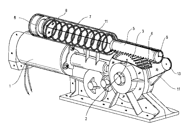
The sole Figure shows the basic structure of the inventive door
drive.
The inventive electro-mechanically driven door drive has a
motor 1, which is in operational connection with a toothed wheel
2. The toothed wheel 2 consists of two toothed discs 3, 4 which
are parallel to each other and are connected to each other by
means of a hub, which hub has a contour with a variable radius.
Thus a slot is formed between the two toothed discs 3, 4.
The toothed wheel 2, respectively the two toothed discs 3, 4 are
meshing with a toothed rack 5, which is provided with a slot 6
extending in the longitudinal direction.
Furthermore, the door drive has a spring 7 serving as an energy
accumulator, one end of said spring bears against the toothed
rack 5 and the other end thereof against an adjustable
abutment 8.
The spring 7 is supported in a housing 9, which, in the
illustrated exemplary embodiment, extends parallel with regard
to the longitudinal axis of the motor 1.
Furthermore, a return pulley 10 is provided, which is disposed
between the toothed wheel 2 and the toothed rack 5.

CA 02652725 2008-11-19
2005034 PC
-5-
A traction means 11 is attached at the hub between the two
toothed discs 3, 4, which means is guided in the slot between
the two toothed discs 3, 4, extends thereafter over the return
pulley 10, through the slot 6 in the toothed rack 5 and through
the spring 7 and so far as to the abutment 8 and is attached to
the latter.
An additional transmission or reduction ratio can be integral part
of the return pulley 10.
By off-setting the centres of the toothed rack 5 and of the spring
7, if necessary, the slotting might be foregone, maybe with a
variable radius.
The inventive door drive is designed either for the use with a
scissor arm assembly or with a slide channel arm. The torque
characteristics are modified through a change of the pre-loading
of the spring 7 effected by the motor 1. In the illustrated
exemplary embodiment, this is realized through a rotation of the
toothed wheel 2, whereby the traction means 11 is wound onto,
respectively unwound from a hub having a variable diameter,
whereby the abutment 8 of the spring 7 is adjusted. Thus the
pre-loading of the spring 7 is likewise changed. On account of
the contour of the hub, that has a variable radius, the torque
characteristics can be controlled and adapted to the respective
transmission mechanism (scissor arm assembly or slide

CA 02652725 2008-11-19
2005034 PC
-6-
channel arm). Thus these drive variants exclusively differ
through the employed hub with the corresponding contour.
Instead of the above described procedure, the pre-loading of
the spring 7 can be changed via a toothed wheel that is integral
of the gear, via the output shaft of the door drive that is
connected to a closer shaft, or through a spring abutment
disposed on a threaded spindle, the drive thereof being effected
via the motor 1 or via a gear shaft. However, on account of the
fixed coupling between motor rotation and spring adjustment, it
1o is not possible to create variants with the above configuration.

CA 02652725 2008-11-19
2005034 PC
-7-
List of reference numerals
1 motor
2 toothed wheel
3 toothed disc
4 toothed disc
5 toothed rack
6 slot
7 spring
8 abutment
9 housing
10 return pulley
11 traction means

Representative Drawing
A single figure which represents the drawing illustrating the invention.
Administrative Status

2024-08-01:As part of the Next Generation Patents (NGP) transition, the Canadian Patents Database (CPD) now contains a more detailed Event History, which replicates the Event Log of our new back-office solution.

Please note that "Inactive:" events refers to events no longer in use in our new back-office solution.

For a clearer understanding of the status of the application/patent presented on this page, the site Disclaimer , as well as the definitions for Patent , Event History , Maintenance Fee  and Payment History  should be consulted.

Event History

Description Date
Inactive: IPC deactivated 2021-11-13
Inactive: IPC assigned 2021-08-05
Inactive: IPC expired 2015-01-01
Application Not Reinstated by Deadline 2011-05-02
Time Limit for Reversal Expired 2011-05-02
Deemed Abandoned - Failure to Respond to Maintenance Fee Notice 2010-05-03
Letter Sent 2009-06-29
Inactive: Single transfer 2009-05-25
Inactive: Correspondence - PCT 2009-04-29
Inactive: Notice - National entry - No RFE 2009-03-26
Inactive: Declaration of entitlement/transfer - PCT 2009-03-26
Inactive: Cover page published 2009-03-19
Inactive: Declaration of entitlement/transfer - PCT 2009-03-16
Inactive: Notice - National entry - No RFE 2009-03-16
Inactive: First IPC assigned 2009-03-04
Application Received - PCT 2009-03-03
National Entry Requirements Determined Compliant 2008-11-19
Application Published (Open to Public Inspection) 2007-12-06

Abandonment History

Abandonment Date Reason Reinstatement Date
2010-05-03

Maintenance Fee

The last payment was received on 2008-11-19

Note : If the full payment has not been received on or before the date indicated, a further fee may be required which may be one of the following

  • the reinstatement fee;
  • the late payment fee; or
  • additional fee to reverse deemed expiry.

Patent fees are adjusted on the 1st of January every year. The amounts above are the current amounts if received by December 31 of the current year.
Please refer to the CIPO Patent Fees web page to see all current fee amounts.

Fee History

Fee Type Anniversary Year Due Date Paid Date
MF (application, 2nd anniv.) - standard 02 2009-05-04 2008-11-19
Basic national fee - standard 2008-11-19
Registration of a document 2009-05-25
Owners on Record

Note: Records showing the ownership history in alphabetical order.

Current Owners on Record
DORMA GMBH & CO. KG.
Past Owners on Record
HOLGER HAENSCH
Past Owners that do not appear in the "Owners on Record" listing will appear in other documentation within the application.
Documents

To view selected files, please enter reCAPTCHA code :


To view images, click a link in the Document Description column. To download the documents, select one or more checkboxes in the first column and then click the "Download Selected in PDF format (Zip Archive)" or the "Download Selected as Single PDF" button.

List of published and non-published patent-specific documents on the CPD .

If you have any difficulty accessing content, you can call the Client Service Centre at 1-866-997-1936 or send them an e-mail at CIPO Client Service Centre.


Document
Description 
Date
(yyyy-mm-dd) 
Number of pages   Size of Image (KB) 
Representative drawing 2008-11-18 1 40
Description 2008-11-18 7 207
Claims 2008-11-18 2 56
Drawings 2008-11-18 1 37
Abstract 2008-11-18 1 17
Notice of National Entry 2009-03-15 1 193
Notice of National Entry 2009-03-25 1 194
Courtesy - Certificate of registration (related document(s)) 2009-06-28 1 102
Courtesy - Abandonment Letter (Maintenance Fee) 2010-06-27 1 172
PCT 2008-11-18 5 156
Correspondence 2009-03-15 1 26
Correspondence 2009-03-25 1 26
Correspondence 2009-04-28 2 89
PCT 2010-07-14 1 45