Note: Descriptions are shown in the official language in which they were submitted.
CA 02652785 2008-11-19
WO 2007/135577 PCT/IB2007/051284
-1-
CATHETER INSERTION SHEATH WITH ADJUSTABLE FLEXIBILITY
FIELD OF THE INVENTION
This invention relates to sheaths for use with catheters and other
applications. Specifically, the invention relates to flexible sheaths with
variable rigidity.
BACKGROUND OF THE INVENTION
Catheters are used extensively in the medical field in various types of
procedures, including invasive procedures. Minimally invasive surgery
involves operating through small incisions, through which instruments are
inserted. These incisions are typically 5 mm to 10 mm in length. Minimally
is invasive surgery is typically less traumatic than conventional surgery, due
in
part to the significant reduction in incision size. Furthermore,
hospitalization
is reduced and recovery periods are shortened as compared with conventional
surgery techniques. Catheters may be tailored to a particular size or form,
depending on the incision and the size of the body cavity or vessel.
The steering of catheters inside the body is a challenging and time-
consuming task in many applications, such as angioplasty and
electrophysiological interventions. To avoid extended exposure of the
physician to radiation, remote control operation systems are under
development. One difficulty with remotely controlled catheters involves
transmitting forces from the back end of the catheter to the tip. A catheter
that is too flexible is unable to transfer force, whereas a catheter that is
too
stiff is unable to maneuver through the difficult curvatures.
SUMMARY OF THE INVENTION
The present invention includes a sheath (10) for guiding materials in a
body cavity. The sheath comprises a tubular structure having an exterior
surface (12) of a sidewall (13) and a lumen (14) enclosed by an interior
CA 02652785 2008-11-19
WO 2007/135577 PCT/IB2007/051284
-2-
surface (16) of the sidewall. The sidewall has a duct (18) containing a
magnetorheological fluid.
Also presented is a method for navigating a sheath (50) adapted to guide
materials in a patient's body, wherein the sheath has a distal end, a proximal
end, and a sidewall having a duct (18) containing a magnetorheological fluid.
The method comprises: introducing the distal end of the sheath to a passage
(62) in the patient's body; manipulating the rigidity of the
magnetorheological
fluid by applying a magnetic field; and positioning the sheath. A navigable
catheter and sheath assembly is also presented. The assembly comprises: a
io sheath (60) for positioning a catheter (64), and the sheath comprises a
tubular structure having an a sidewall and a lumen enclosed by an interior
surface of the sidewall. The sidewall has a duct containing a
magnetorheological fluid. The assembly further comprises a catheter (64)
adapted for insertion through the lumen of the sheath; a magnetic field
is generating apparatus (66) adapted to generate a magnetic field which
manipulates the rigidity of the magnetorheological fluid.
BRIEF DESCRIPTION OF THE DRAWINGS
FIGURE 1 is a schematic of a catheter sheath with a U-shaped duct of
20 magnetorheological fluid on the exterior sidewall in accordance with one
embodiment of the invention.
FIGURE 2 is a schematic of a catheter sheath with a W-shaped duct of
magnetorheological fluid on the exterior sidewall in accordance with one
embodiment of the invention.
25 FIGURE 3 is a schematic of a catheter sheath with a duct of
magnetorheological fluid circumscribing the exterior sidewall in accordance
with one embodiment of the invention.
FIGURE 4 is a schematic of a catheter sheath with multiple parallel ducts
of magnetorheological fluid on the exterior sidewall in accordance with one
30 embodiment of the invention.
FIGURE 5 is a flow chart that schematically illustrates a method for
navigating a catheter sheath in accordance with one embodiment of the
invention.
CA 02652785 2008-11-19
WO 2007/135577 PCT/IB2007/051284
-3-
FIGURE 6 is a schematic of a catheter sheath and catheter assembly in
accordance with one embodiment of the invention.
DETAILED DESCRIPTION OF THE INVENTION
The invention describes a remote controlled sheath for insertion of
catheters, or other materials. The flexibility or stiffness of the sheath can
be
controlled externally by modulating the strength of an applied magnetic field.
The facile adjustment of the flexibility of the sheath provides the operator
greater control and reduces the danger of causing damage to the patient
tissue during catheter insertion. The sheath varies in rigidity because it
contains a magnetorheological fluid that transitions between a rigid, solid-
like
state and a liquid fluid state as a function of magnetic field.
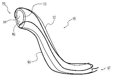
Referring to Figure 1, a sheath 10 for positioning a catheter is shown as a
tubular structure having an exterior surface 12 of a sidewall 13 and a lumen
14 enclosed by an interior surface 16 of the sidewall 13, the sidewall having
a
duct 18 containing a magnetorheological fluid. The lumen can be adapted to
transport and position a catheter. The sheath is appropriate to transport and
position catheters for a variety of purposes, including electrophysiology
procedures, angioplasty, and ablation. The lumen can also be adapted to
transport and apply coils, liquids, or other materials as appropriate.
The sheath 10 can be formed of a conventional, bendable tubing material
of low stiffness, combined with a magnetorheological fluid (MRF) contained in
a duct 18 on the sheath. When magnetic fields are applied, the MRF becomes
rigid in regions exposed to local magnetic fields. As the strength of the
magnetic field increases, the rigidity of the fluid increases. For applying
such
fields, an external magnetic coil can be employed. Alternatively, the magnetic
field can be applied to the end of the sheath. With the magnetic field applied
to one end of the sheath, the MRF itself acts as a line of high magnetical
conductivity and causes the particles in the magnetorheological suspension to
coagulate.
A magnetorheological fluid is a liquid that hardens near a magnetic field,
and becomes liquid again when the magnetic field is removed. The term
CA 02652785 2008-11-19
WO 2007/135577 PCT/IB2007/051284
-4-
magnetorheological fluid (MRF) refers to liquids that solidify in the presence
of
a magnetic field. Magnetorheological fluids have micrometre scale magnetic
particles, and the magnetorheological effect in fluids develops when the
particle size is about 10 nanometers or larger. The particles can be iron,
magnetite, cobalt, or other magnetic materials, and the surrounding liquid can
be an oil, water, wax, or other solvent. Surfactants can be used to make the
suspension more stable, for example, trapping particles in micelles to
maintain
separation.
Again referring to Figure 1, the duct 18 on the sheath 10 may extend
io from the proximal end 17 of the tubular structure to the distal end 19 of
the
tubular structure. The duct of the sheath can take a variety of configurations
to optimize performance for various catheter insertion operations. For
example, the duct may extend from the proximal end to the distal end of the
tubular structure repeatedly, as shown in Figures 1 and 2.
is Figure 2 is a simplified schematic of a sheath 20, which is similar to the
sheath 10 shown in Figure 1. In Figure 2, the duct 22 repeatedly extends
between the distal and proximal ends of the sheath. In another embodiment
of the invention, a serpentine pattern may continue around the full
circumference.
20 Another exemplary pattern for the duct of MRF is shown in Figure 3.
Here, the duct 32 extends around the circumference of the sheath 30. The
duct may be formed as a continual coil that wraps around the sheath, or
alternatively may be formed from parallel concentric rings around the sheath.
Figure 4 illustrates yet another embodiment of the invention in which the
25 duct 42 is formed from several parallel segments running along the sheath
40
oriented substantially parallel to the sheath's longitudinal axis. In any of
the
configurations presented, the duct can reside on the exterior surface of the
sheath sidewall, on the interior surface, or imbedded within the sheath
sidewall.
30 The invention also includes a method for navigating a sheath adapted to
guide materials, such as a catheter in a patient's body. In this method, the
sheath, which has a duct containing a magnetorheological fluid, is introduced
CA 02652785 2008-11-19
WO 2007/135577 PCT/IB2007/051284
-5-
into a passage in the patient's body. A passage includes a body cavity or
blood vessel.
In navigating the sheath and catheter in the passage, the rigidity of the
magnetorheological fluid can be manipulated to facilitate advancement of the
sheath by applying a magnetic field. Manipulating the rigidity of the MRF
facilitates insertion and placement of the sheath. In positioning the sheath,
if the passage includes a very tight radius of curvature, the rigidity of the
MRF can be adjusted to allow more flexibility and maneuverability. Where
the passage presents an area that is difficult to traverse, the rigidity of
the
io MRF can be increased through the application of a magnetic field to permit
transference of force in maneuvering the sheath.
Accordingly, the navigating and positioning of the sheath can include
applying a magnetic field to the sheath and varying the applied magnetic
field. The magnetic field can be applied as an external magnetic field.
is Alternatively, the magnetic field can be applied to one end of the sheath
and
the magnetic particles in the MRF can be used to create an internal magnetic
field. Also, magnetic fields of different strength may be applied to the
distal
end of the sheath from the proximal end of the sheath.
The magnetic field can be adjusted to manipulate the rigidity of the MRF
20 to create different regions of rigidity in the sheath. For example, regions
at
the distal end of the sheath could be in a flexible state, while regions at
the
proximal end of the sheath remain rigid.
In navigating the sheath through the passage, the MRF may be
controlled iteratively to correlate with conditions in the passage as the
25 sheath advances by adjusting the applied magnetic field. Aspects of this
process are illustrated in a flowchart in Figure 5. The sheath is introduced
to
a body passage 50, and the rigidity of the MRF is manipulated via an applied
magnetic field 52. If the MRF rigidity is appropriate to position the sheath
54, then the sheath is positioned in the passage as desired 56. Reference to
30 positioning the sheath in the passage includes advancing the sheath,
removing the sheath, and fixing the position of the sheath or catheter. If
the MRF rigidity is not appropriate to position the sheath 58, then the
rigidity
CA 02652785 2008-11-19
WO 2007/135577 PCT/IB2007/051284
-6-
of the MRF is manipulated by adjusting the magnetic field 52. This process
can be repeated iteratively until the procedure is completed.
Another embodiment of the invention is a navigable catheter and sheath
assembly. Referring to Figure 6, the sheath 60 of the assembly is inserted
into a body cavity or passage 62. The assembly includes a catheter 64 and a
magnetic field generating apparatus 66 which is adapted to generate a
magnetic field. The magnetic field serves to manipulate the rigidity of the
magnetorheological fluid.
The assembly can also include a control unit 68 at the proximal end of the
sheath. The control unit allows for controlling the sheath remotely. The
control unit can be used to control the sheath, the catheter, or both.
The invention can be applied in the use of a multitude of catheters and
sheaths for manipulations inside of the patient, with particularly useful
applications in positioning electrophysiology (EP) catheters. Typical
catheters
is may range in lengths of from about 35 cm to about 175 cm and more typically
from about 50 cm to about 160 cm. The sheath will be approximately the
same length.
The diameters of the catheter and sheath can vary between the distal and
proximal ends. Preferably, the diameter should be as small as possible within
the practical manufacturing limits so as to present the least trauma and the
most conformability to the sheath. Typically, the distal portion of the sheath
may vary with an outside diameter from about 0.6 mm (2 French) to about 6
mm (18 French) and more preferably, from about 0.6 mm (2 French) to about
2.3 mm (7 French). The outside diameter of the proximal portion can vary
from about 1 mm (3 French) to about 6.3 mm (19 French) and more
preferably, from about 1 mm (3 French) to about 2.7 mm (8 French). For
example, the diameter of the distal portion may be 1.55 mm (4.5 French) and
the diameter of the proximal portion may be 1.7 mm (5 French).
Although the invention is illustrated and described herein with reference
to specific embodiments, the invention is not intended to be limited to the
details shown. Rather, various modifications may be made in the details
within the scope and range of equivalents of the claims and without departing
from the invention.