Note: Descriptions are shown in the official language in which they were submitted.
CA 02653730 2008-12-23
WO 2008/000072 PCT/CA2007/001136
ABRASION ASSISTED WIRE ELECTRICAL DISCHARGE MACHINING
PROCESS
FIELD OF INVENTION
[0001 ] This invention relates to wire electrical discharge machining.
BACKGROUND OF THE INVENTION
Electrical Discharge Machining (Prior Art)
[0002] Electrical Discharge Machining (EDM) is a machining process which is
widely used in the manufacture of precision components. In EDM, a pulsed
voltage is
applied between a tool and a workpiece which are physically separated by a
small gap
of the order of 10-50 m, in the presence of a dielectric fluid. Heat
generated by
controlled, rapid and repetitive electrical spark discharges occurring between
the tool
and the workpiece is utilized to melt, vapourise and remove workpiece
material.
Wire Electrical Discharge Machining (Prior Art)
[0003] Wire EDM is a variant of the EDM process, in which the tool electrode
is in
the form of a flexible wire, typically about 300 m or less in diameter, which
translates along its axis. This process is well adapted for machining
intricate
geometries in hard materials with high precision. However, major shortcomings
are:
(i) low material removal rate which renders the process rather slow and
expensive, and
(ii) the presence of a crack-infested re-cast layer of work material on the
machined surface due to poor material ejection efficiency which necessitates
time-
consuming post-EDM finishing operations such as polishing for critical high
performance components to improve fatigue life, see for example US 4,367,389
and
US 2005/0102809.
[0004] A requirement to develop more environmentally friendly processing
methods
has seen the emergence of the dry or near-dry EDM process. This process uses a
gas
such as air or oxygen in the discharge gap in place of conventional oils or de-
ionized
CA 02653730 2008-12-23
WO 2008/000072 PCT/CA2007/001136
water. However, use of this process is currently limited because of re-
deposition of
machining debris as well as low removal rates due to frequent shorting.
Wire Saw Technology (Prior Art)
[0005] The wire saw process is widely used in the manufacture of wafers in the
semiconductor industry. Initial developments in wire saw technology utilized a
steel
wire with the application of an abrasive slurry solution in the cutting zone.
To
overcome the technological limitations of this process, such as low cutting
speeds and
non-uniform wafer thickness due to wire wear, modern wire saw processes employ
fixed abrasive wires. The wire is either fed from one spool to another and
then
reversed to continue the process, or used in a closed loop so as to
continually feed in
the same direction.
Electrical Discharge Diamond Grinding (Prior Art)
[0006] Electrical Discharge Diamond Grinding (also known as Abrasive
Electrical
Discharge Grinding) is a process which integrates EDM and conventional
grinding.
For further information, see P. Koshy, V.K. Jain, G.K. Lal., Mechanism of
material
removal in electrical discharge diamond grinding, International Journal
ofMachine
Tools and Manufacture 36 (1996) 1173-1185, and J. Kozak, K.E. Oczos, Selected
problems of abrasive hybrid machining, Journal of Materials Processing
Technology
109 (2001) 360-366. The role of the electrical discharges which occur at the
grinding
zone is to thermally soften the work material in order to facilitate grinding
and to
dress/declog the grinding wheel in-process for improved wheel performance.
[0007] An object of the present invention is to address the above-mentioned
problems
inherent to wire EDM and improve the material removal rate and provide a
better
surface quality.
SUMMARY OF THE INVENTION
[0008] The present invention provides a method of wire electrical discharge
machining comprising applying a pulsed voltage between a tool electrode and a
workpiece which are physically separated by a working gap, the tool electrode
being
-2-
CA 02653730 2008-12-23
WO 2008/000072 PCT/CA2007/001136
in the form of a wire with an electrically conductive core and an external
surface
embedded with an electrically non-conductive abrasive material.
[0009] In a conventional wire-EDM process, high removal rates and good surface
quality are mutually exclusive, with each of these being obtained at the
expense of the
other. Since material removal in accordance with the present invention takes
place by
the combined mechanisms of melting/vapourization and abrasion, the removal
rate is
higher and the machined surface is of better quality because the recast
material is
largely removed by abrasion.
BRIEF DESCRIPTION OF THE DRAWINGS
[0010] Embodiments of the invention will now be described by way of example
with
reference to the accompanying drawings of which:
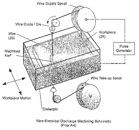
[0011] Fig. 1 is a schematic view showing a typical known wire electrical
discharge
machining configuration;
[0012] Fig. 2 is a similar view showing a typical known configuration for wire
saw
slicing of wafers;
[0013] Fig. 3 is a similar view showing a typical known configuration of
electrical
discharge diamond grinding;
[0014] Fig. 4 is a schematic view showing abrasion assisted wire electrical
discharge
machining in accordance with one embodiment of the present invention;
[0015] Fig. 5 is similar to Fig. 4 but shows more detail; and
[0016] Fig.s 6(a) and 6(b) shows schematic views of locating and guiding the
abrasive
wire in accordance with other embodiments of the invention.
DESCRIPTION OF PREFERRED EMBODIMENTS
[0017] Referring to the drawings, the invention can be carried out using a
conventional wire electrical discharge machining apparatus of the kind shown
in Fig.
1, but modified to accept wire 20 in accordance with one embodiment of the
invention
-3-
CA 02653730 2008-12-23
WO 2008/000072 PCT/CA2007/001136
which comprises an electrically conducting core 22, see Fig. 4 for
clarification which
is embedded with non -conductive abrasives 24.
[0018] The wire 20 translates along its axis lateral to the workpiece 28, as
indicated
by arrow 32 in Figs. 4 and 5. The workpiece is fed relative to the wire axis,
as
indicated by arrow 30 in Fig. 4, under servo control such that a gap is
maintained
between the workpiece and the wire core.
[0019] The gap g, between the wire core 22 and the workpiece 28, see Fig. 5,
may be
controlled electrically and, if so, it is necessary that the wire core and the
workpiece
be electrically conductive. For the same reason, in order that the abrasive
grain 24 and
spark discharge 26 are both operative simultaneously, the abrasive has to be
electrically non-conductive and have a nominal protrusion height Ph greater
than the
nominal gap width gK,, see Fig. 5. Hence, for a given average gap width, a
wire with
an appropriate grit size can be chosen or alternatively, for a given wire, the
gap width
can be altered by changing the servo control parameters.
[0020] The EDM servo control parameters can be further adjusted with reference
to
feedback from the gap based on measured parameters which may include but are
not
limited to machining force and wire deflection. The additional feedback can be
used
to control the extent of material removal by mechanical abrasion for a given
wire and
workpiece material.
[0021 ] Wire implanted with electrically non-conductive abrasives, for example
diamond as is typically used for wire saw cutting applications as described
previously
with reference to Fig. 2, may be used. However, instead of diamond, it may be
desirable to employ another electrically non-conducting or semi-conducting
abrasive
which would serve the same purpose at a significantly lower expense. Thus,
alternatives may include but are not limited to aluminum oxide, cubic boron
nitride or
silicon carbide.
[0022] As shown in Fig. 1, the wire 20 is positioned with respect to the
workpiece 28
and guided along its axis by wire guides. It is also desirable in wire-EDM to
supply
the electrical power to wire through contacts which are located just above and
below
-4-
CA 02653730 2008-12-23
WO 2008/000072 PCT/CA2007/001136
the confines of the workpiece so as to minimize resistive heating and
inductance in the
circuit.
[0023] In some circumstances, the use of a wire with abrasives embedded around
the
entire circumference of the wire as shown in Fig. 4, may cause rapid
deterioration of
both the wire guides and the electrical contacts due to severe abrasion. To
avoid such
a problem, a wire in accordance with another embodiment of the invention has
embedded abrasives only partially around the wire perimeter, as shown in Fig.
6(a).
The wire cross section may be a circular, polygonal or semi-polygonal cross
section,
including polygons having between three and five sides, for example as shown
in Fig.
6(a). The sector of the wire which is free of abrasives can thus be used to
supply
electrical power to the wire core without abrading the electrical contacts.
The
polygonal shape is utilized to locate and guide the wire along its axis with
no abrasion
of the wire guide 34.
[0024] The wire and the workpiece are oriented such that the machined surface,
or
specifically the instantaneous feed direction, is normal to the sector of the
wire which
is embedded with abrasives. This may be accomplished by various means, which
include but are not limited to the addition of a rotary axis on the wire
guides allowing
them to be rotated to match the required feed direction, or the addition of a
rotary axis
on or below the XY work table which will enable the workpiece to be oriented
such
that the feed direction is normal to the abrasive wire sector or a combination
thereof.
[0025] A wire with abrasives embedded around the circumference of the wire,
either
partially or fully as shown in Fig. 4 used in conjunction with grooved
rotational guides
so as to minimize relative motion between the wire and the guiding elements
35, see
Fig. 6(b), as opposed to conventional stationary wire guides which could be
subject to
excessive wear as a result of abrasion by the wire. The application of
electrical power
may be accomplished by various means which include but are not limited to the
use of
liquid-metal coupling (including mercury and other low melting temperature
metals),
electrolytic coupling or conductive brushes.
[0026] In use of the invention in conjunction with existing dry or near-dry
WEDM
methods, the non-conducting abrasives will act to electrically isolate the
workpiece
-5-
CA 02653730 2008-12-23
WO 2008/000072 PCT/CA2007/001136
and wire core. Also, the abrasive action will further remove the recast layer
and any
re-deposited debris.
[0027] Other embodiments of the invention will now be readily apparent to a
person
skilled in the art from the foregoing description, the scope of the invention
being
defined in the appended claims.
-6-