Note: Descriptions are shown in the official language in which they were submitted.
CA 02653812 2008-11-28
WO 2007/140569
PCT/CA2006/000909
REMOTE MANIPULATOR FOR MANIPULATING LIVE MULTIPLE SUB-
CONDUCTORS IN A SINGLE PHASE BUNDLE
Field of the Invention
This invention relates to a device which is attached to the boom of a crane or
similar device, and the corresponding method for the precise and remote
manipulation of live sub-
conductors in a single phase bundle of an energized overhead high voltage
transmission line.
Background of the Invention
As we describe in our United States Patent No. 5,538,207, which issued July
23,
1996 for our Boom-Mountable Robotic Arm, high voltage transmission and
distribution lines are
typically strung between a series of spaced-apart support structures or poles.
The conductors are
connected to insulators mounted on or suspended from cross arms extending at
the upper end of
transmission or distribution poles, or conductor support points built into
transmission structures.
Periodically it is necessary to replace or repair the poles or structures,
cross arms and insulators to
maintain the electrical circuit in good working order. It is preferable if
this maintenance and repair
work can be performed without de-energizing the conductors in order to avoid
an interruption of
service to consumers, or to avoid the necessity of purchasing power from an
alternative source, or
other system disruptions.
Hot line repair work is a potentially hazardous undertaking. Safety
regulations
require that linemen maintain a minimum work clearance or "limit of approach"
from energized
conductors. The limit of approach varies depending upon the voltage of the
conductors in question.
Conventional procedures used by linemen to temporarily support energized
conductors in order to enable repair of damaged or obsolete components involve
the use of
insulated wire tongs, lift poles and rope blocks in labour-intensive, complex
rigging arrangements.
1
CA 02653812 2008-11-28
WO 2007/140569 PCT/CA2006/000909
Conventional fiberglass insulated tools are limited to use only in good
weather. Any accumulation
of moisture which may impair their insulating property requires that the job
be stopped, and that
the conductors be placed in an insulator which is rated for all-weather use.
Fujimoto in United States Patent Nos. 5,107,954 and 5,183,168 which issued
respectively on April 28, 1992 and February 2, 1993 describes an operator
cabin mounted on the
distal end of a vertical mounted boom, the operator cabin having at least one
manipulator
operatively connected to the front side of the cabin. A pair of manipulators
are illustrated. The
manipulators are adapted to manipulate electrical components while energized.
In applicant's view
the device of Fujimoto appears to be limited to electric components having a
relatively lower
voltage, for example, 46 kV and below.
Several auxiliary cross arms have also been proposed in the past for
temporarily
supporting conductors, thereby reducing the need for labour-intensive "stick
work" by linemen.
For example, U.S. Pat. No. 4,973,795, which issued to Sharpe on 27 Nov., 1990,
relates to an
auxiliary cross arm consisting of an insulated boom fitted with polymer
insulators and conductor
hooks for releasably engaging energized conductors. The Sharpe boom is
suspended from a crane
above the transmission lines to be serviced.
Auxiliary cross arms for temporarily lifting and supporting energized
conductors
from below are also well known. Such cross arms typically have sleeves which
are connectible to
the boom jibs of derrick or bucket trucks.
As we also describe in our United States Patent No. 6,837,671, which issued
January 4, 2005 for our Apparatus for Precisely Manipulating Elongate Objects
Adjacent to and
such as Energized Overhead High Voltage Transmission Lines, the replacement
and installation
of cross arm members or insulators on overhead transmission towers is
generally accomplished,
whenever possible, while the electrical transmission lines are energized. It
is common to find
several rows of transmission structures supporting two or more vertically
separate electrical
2
CA 02653812 2008-11-28
WO 2007/140569 PCT/CA2006/000909
transmission lines located in relatively close proximity. This confined
overhead working area
emphasizes the need for the precise elevating and manipulation of objects so
as to avoid accidental
arcing between the energized lines and the object with obvious dire
consequences to workmen and
machinery. A convenient practice is to employ a helicopter to elevate such
objects to workmen on
the tower. However, where a structures supports vertically separated energized
lines, wind gusts
and rotor downwash make this practice difficult and may require the de-
energizing of a portion of
the electrical transmission line. Such de-energizing is undertaken only as a
last resort.
As we also describe in our published United States Patent Application No.
10/927,467, published under Publication No. 2005/0133244A1 on June 23, 2005
for Live
Conductor Stringing and Splicing Method and Apparatus, typically, alternating
current is
generated in a three-phase configuration. The three phases, B phase and C
phase are all
transported over separate conductors. Each such separate single phase
conductor may be referred
to in the industry as a phase. It is appreciated by one skilled in the art,
that in some systems, more
than one conductor (referred to herein as sub-conductors) carries the power
load for a particular
phase. This may be done in instances when a load is greater that a single
conductor can
accommodate. In such cases multiple (bundled) sub-conductors are often located
next to each
other and may hang from the same insulator as shown herein in Figure 1. The
conductors may be
separated by spacers. Single insulators may be configured to carry double sub-
conductors, two
sub-conductors per phase, under a single yoke plate attached to the insulator.
Power lines consist of one, two or three phase systems. Each phase is
electrically
different from the other, that is they are at different electrical potentials.
For example: in a simple
house circuit of 120/240 volts, you have 3 wires (or conductors), two phase
wires and a neutral or
ground wire. The voltage or potential difference between the two phase wires
and the neutral is
120 volts and the difference between the two phase wires is 240 volts. This is
a two phase system.
In a single phase system you have two wires or conductors, one at an
electrical potential and the
other at ground or neutral potential. In a three phase system there are three
wires all at a different
3
CA 02653812 2008-11-28
WO 2007/140569
PCT/CA2006/000909
electrical potential from the other. Some systems may have a fourth ground or
neutral wire which
is electrically at the same potential difference from the phases or three
wires.
Conductors are the wires or power lines in a power system. Each phase of a
power
line may consist of 1, 2, 3, 4 or 6 wires or conductors which are referred to
as sub-conductors.
Each sub-conductor is at the same electrical potential as the others
regardless of the number of
sub-conductors. Generally sub-conductors are used at the higher voltages (EHV)
up to 765 kV and
are larger and heavier.
Summary of the Invention
It has now been found to be desirable in some circumstances, and it is an
object of
the present invention, to provide or attain higher surge impedance loading
(SIL) on overhead lines.
To accomplish this it is advantageous to increase bundle spacing. It may also
be advantageous to
decrease phase spacing. It is also been proven that on two bundle lines,
tipping the bundle
(adjusting the height of the sub-conductors so that they are not at the same
elevation) lowers the
chances of line galloping or vibration, thus reducing conductor damage.
The overhead lines studied for improving SIL were of the flat configuration.
That
is, the phases were supported from the tower by for example an I-I-I or I-V-I
insulator
configuration at typical distances of 9 to 10m apart. This is referred to as
the phase-to-phase
spacing.
Methods to decrease the phase-to-phase spacing may involve the use of
interphase
spacers or insulators, originally developed to counter conductor galloping
normally associated with
ice forming onto conductors and responsible for setting up large conductor
movement. No
modification or alteration to the tower is necessary as the interphase spacer
is installed in the
middle of the span some 10m away from the tower. In one embodiment of the
present invention,
4
CA 02653812 2008-11-28
WO 2007/140569
PCT/CA2006/000909
the apparatus provides for adjusting the horizontal spacing of insulators so
that the phase spacing
may be adjusted.
Increasing the bundle spacing may involve mainly hardware modifications to the
line material that attaches the conductor to the insulator. An example of a
group of lines which
may benefit from improved SIL performance includes a typical turn conductor
configuration in a
horizontal arrangement spaced apart by a typical distance of 380mm (15 inches)
apart by a yoke
plate. Two examples for improving the spacing between the sub-conductors of a
phase include,
firstly, dropping one conductor by introducing an extension link between the
yoke plate and the
suspension clamp to space the conductors apart, for example, 700mm (23
inches). The other
example involves a bigger yoke plate to space the conductors apart
horizontally a distance of, for
example, 700mm. The present invention assists in achieving an increased
somewhat optimized
spacing between conductors for improved SIL performance.
It is difficult to achieve such spacing by adjusting the level of the bundle
using a
prior art single point conductor lifter. Because the conductor bundles are
mounted at opposite
ends of a yoke plate, itself mounted to an insulator at a single central
point, the weight of both
bundles has to be simultaneously supported to keep the yoke plate from
pivoting or twisting or
binding on the insulator and thereby possibly damaging it.
In summary, the remote manipulator according to the present invention for
separating multiple sub-conductors in an energized single phase bundle, may be
characterized in
one aspect as including a rigid support member such as a boom extension
mountable on the end of
a boom and at least first and second actuators mounted on the support member,
wherein each
actuator is independently actuable of the other. An insulator or insulators
are mounted on each
actuator. A selectively releasable coupler is mounted on each insulator for
selectively releasable
coupling of each insulator to a corresponding sub-conductor in a live or
energized single phase
bundle of sub-conductors. The actuators are arranged so as to, when
selectively actuated by
actuation means such as a hydraulic circuit, extend corresponding insulators
independently of one
5
CA 02653812 2008-11-28
WO 2007/140569
PCT/CA2006/000909
another from the support member to thereby separate from each other by an
optimized separation
distance the distal ends of each insulator. When the corresponding sub-
conductors of the single
phase bundle are releasably coupled to the corresponding distal ends of the
insulators the surge
impedance loading of the single phase bundle may be improved by separation of
the corresponding
distal ends of the insulators and the sub-conductors by the optimized
separation distance.
In one embodiment each actuator actuates a corresponding insulator linearly
along a
linear actuation trajectory. Each actuator may be mounted on a common base
which is itself
mounted on the support member. The actuation trajectories may be parallel. The
base may be
selectively pivotally mounted on the support member and selectively pivotable
relative thereto by
actuation of a selectively actuable pivoting means. For example, an actuator
such as a hydraulic
cylinder may pivot the base about a pivot point or fulcrum on the end of the
support member. The
base may for example be an arm cantilevered from the end of the support, a
mounting bracket
supporting the actuators and corresponding insulators symmetrically about the
pivot point, or other
structural embodiments stably holding the actuators for accurate position of
the distal ends of the
insulators with their sub-conductor couplers.
The actuation trajectories extend linearly upwardly or downwardly from the
support
and the base in which case the optimized separation distance may be a
substantially vertical
spacing between the corresponding separated sub-conductors. Alternatively the
actuation
trajectories may be substantially horizontal in which case the separation is
also horizontal.
In one embodiment the actuators include corresponding prime movers such as
hydraulic cylinders mounted to the base and include distal ends which are
flexible members such
as cables extending from the prime movers. The flexible members may extend
horizontally and/or
depend downwardly from the base along the actuation trajectories. The prime
movers of the
actuators may be mounted substantially horizontally along the base, in
particular where the base is
an elongate arm. That is, in one embodiment the hydraulic cylinders are
mounted along the arm so
as to be substantially parallel to a longitudinal axis of the arm, the
insulators may be elongate and
6
CA 02653812 2008-11-28
WO 2007/140569
PCT/CA2006/000909
depend from the distal ends of the flexible members so as to hang downwardly
lengthwise
substantially co-axially with flexible members, for example the cables.
In one embodiment, the actuators are hydraulic cylinders mounted so as to
extend
substantially vertically upwardly for releasable engagement with the
corresponding sub-conductors
positioned above the base. The insulators may be elongate and are rigidly
mounted to distal ends
of the actuators and are actuable so that longitudinal axes of the insulators
extend substantially
along the linear actuation trajectories. Advantageously, a lateral spacing
along the base between
the actuators is substantially equal to the lateral spacing between the
corresponding sub-conductors
in the single phase bundle.
In use the apparatus according to the present invention for separating
multiple sub-
conductors in a live single phase bundle, includes a method comprising:
a) providing a rigid support member mountable on the end of a boom
b) providing at least first and second actuators mounted on the
support member,
wherein each actuator is independently actuable,
c) providing an insulator mounted on each actuator and a selectively
releasable
coupler mounted on each insulator for selectively releasable coupling of each
insulator to a corresponding sub-conductor in a live single phase bundle of
sub-
conductors,
d) arranging the actuators and actuating the actuators by actuation means
so as to
extend corresponding insulators independently of one another from the support
member,
7
CA 02653812 2008-11-28
WO 2007/140569
PCT/CA2006/000909
e) releasably coupling to the distal ends of each insulator the
corresponding sub-
conductors of the live single phase bundle, and
0 separating from each other by an optimized separation
distance distal ends of the
each insulator, so as to improve the surge impedance loading of the single
phase
bundle by separation of the corresponding distal ends by the optimized
separation
distance.
The method may also include the steps of:
g) providing that each actuator actuates a corresponding
insulator linearly along a
linear actuation trajectory and that the actuation trajectories for each
actuator are
parallel,
h) of providing a common base and that each actuator is mounted on the
common
base and the base is mounted on the support member and providing that the base
is
selectively pivotally mounted on the support member and providing a
selectively
actuable pivoting means for pivoting the base support member
i) orienting each actuator so that the actuation trajectories extend
upwardly,
downwardly or horizontally from the support and the base, wherein the
optimized
separation distance is the spacing between the corresponding separated sub-
conductors,
D laterally spacing the actuators along the base so that the lateral
spacing between the
distal ends of the actuators is substantially equal to lateral spacing between
the
corresponding sub-conductors in the single phase bundle.
8
CA 02653812 2008-11-28
WO 2007/140569
PCT/CA2006/000909
Brief Description of the Drawings
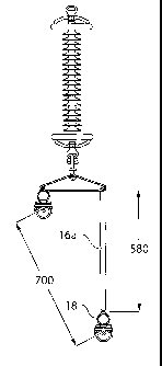
Figure 1 is a partially cut away illustration of prior art overhead
transmission line
structure.
Figure 2 is an enlarged view of a single insulator mounted yoke plate
supporting
two sub-conductors from the view of Figure 1.
Figure 2a is the view of Figure 2 with the right hand sub-conductor lowered
and a
fixed rigid link inserted between the lowered sub-conductor and the yoke plate
so as to increase
the spacing between the suspension clamps.
Figure 3a is one alternative embodiment according to the present invention,
with
the sub-conductor lines not illustrated, in preparation for adjusting the
spacing between the pair of
sub-conductors in the center phase.
Figure 3b is the view of Figure 3a in an embodiment of the present invention
operating on an outside phase.
Figure 4a is, in side elevation view, one embodiment of the present invention
mounted onto the end of a boom.
Figure 4b is, in partially cut away end elevation view, the embodiment of
Figure 4a.
Figure 4c is, in top view, the embodiment of Figure 4a.
Figure 4d is, in side elevation view, the embodiment of Figure 4a with the
actuators
both fully extended.
9
CA 02653812 2008-11-28
WO 2007/140569
PCT/CA2006/000909
Figure 4e is, in side elevation view, the embodiment of Figure 4d with the
actuators
both fully retracted.
Figure 4f is, in side elevation view, the embodiment of Figure 4d with the
near
actuator fully extended and the far actuator fully retracted so as to raise
the right insulator while
leaving the left insulator lowered.
Figure 5a is, in side elevation view, a further alternative embodiment of the
present
invention mounted onto the end of a boom.
Figure 5b is, in side elevation view, the embodiment of Figure 5a with the
right
hand actuator extended so as to elevate the corresponding right hand
insulator.
Figure 5c is, in side elevation view, the embodiment of Figure 5a with the
left hand
actuator extended and the right hand actuator retracted so as to raise the
left hand insulator.
Figure 5d is, in partially cut away partially exploded view, the left and
right hand
actuators of Figure 5b in an enlarged view.
Figure 5e is, in end elevation view, the embodiment of Figure 5a.
Figure 6a is a further alternative embodiment according to the present
invention in
side elevation view.
Figure 6b is, in side elevation view, the embodiment of Figure 6a with the
actuator
mounting bracket pivoted relative to the boom extension.
Figure 6c is, in side elevation view, the embodiment of Figure 6a with the
left and
right hand actuators fully extended so as to raise both the left and right
hand insulators.
CA 02653812 2008-11-28
WO 2007/140569
PCT/CA2006/000909
Figure 6d is a section view along lines 6d-6d in Figure 6a.
Figure 6e is, in side elevation view, the boom extension of Figure 6a.
Figure 7a is, in side elevation view, a further alternative embodiment
according to
the present invention.
Figure 7b is, in top view, the embodiment of Figure 7a.
Detailed Description of Embodiments of the Invention
In the accompanying drawing figures, similar characters of reference denote
corresponding parts in each view. As shown in the prior art, it is known in
the prior art to suspend
from structures10 energized, that is, electrically live, overhead transmission
lines 12 by means of
conventional insulators 14 suspended so as to depend downwardly from the cross
arms of the
towers. Often, within a single phase bundle, the single phase will be carried
by multiple sub-
conductors 12a. Conventionally, a pair of such sub-conductors 12a will be
supported from a cross
arm 10a by yoke plate 16, better seen in Figure 2, itself suspended by a
insulator(s) 14.
The capacity of the single phase bundle may be improved if the surge impedance
loading can also be improved. The surge impedance loading can be improved by
increasing the
spacing between sub-conductors 12a, for example, increasing the separation
distance d1 between
sub-conductors 12a suspended by couplings such as suspension clamps 18 from
yoke plate 16.
One way to increase the spacing between the sub-conductors 12a suspended on
yoke plate 16, is to
drop one of the sub-conductors for example in direction A in Figure 2 so as to
lower the right hand
sub-conductor 12a by distance d2. The resulting separation between the left
and right sub-
conductors 12a is a separation of distance d3. Thus where the lateral spacing
provided by a
conventional yoke plate 16 is approximately 380 millimeters (15 inches)
between couplers 18, so
11
CA 02653812 2008-11-28
WO 2007/140569
PCT/CA2006/000909
that distance di is 380 millimeters, lowering the right sub-conductor 12a in
direction A by a
distance d2 of approximately 580 millimeters, results in a separation between
the left and right sub-
conductors 12a by a distance d3 of approximately 700 millimeters (23 inches).
As seen in Figure
2a a fixed rigid link 16a may be inserted between the yoke plate and the
lowered coupler 18 to
maintain the separated spacing between the sub-conductors. The present
invention provides for
increasing the separation between the sub-conductors from distance di to
distance d3 in the
illustrated example, which is not intended to be limiting but rather which
exemplifies how one
solution according to the present invention may be implemented.
As seen in Figures 3a and 3b, in implementing the method and apparatus
according
to the present invention, a conventional vehicle 20 having a telescoping boom
22 may be parked
adjacent to the structure 10. An insulated boom extension 24 may be mounted to
the distal end
22a of boom 22. Insulated boom extension 24 is alternatively referred to
herein as a rigid support
member although it is not intended that the meaning of the term rigid support
member is to be
limited to meaning solely an insulated boom extension as other support means
mounted to the end
22a of boom 22 will work.
A pivotable base, illustrated in Figures 3a and 3b as a cross member 26, is
pivotally
mounted to boom extension 24 for pivoting relative thereto upon actuation of
an actuator such as
hydraulic cylinder 28 mounted so as to extend between boom extension 24 and
cross member 26.
A rigid cantilevered extension arm 30 may be mounted to cross member 26 where
it is required to
reach for example a center single phase bundle 32 suspended from the structure
10. As seen in
Figure 3b, in order to reach single phase bundle 34, extension 30 is not
required.
In the illustrated embodiments of Figures 3a and 3b, which are not intended to
be
limiting, a pair of insulators 36a and 36b are suspended on corresponding
cables 38a and 38b. The
cables are attached to a pair of hydraulic actuators 40a and 40b, cable 38a
being connected to
actuator 40a, and cable 38b being connected to actuator 40b so that insulators
36a and 36b and
12
CA 02653812 2008-11-28
WO 2007/140569
PCT/CA2006/000909
their corresponding suspension clamps may be raised or lowered independently
by actuation of
their corresponding actuators 40a and 40b.
A corresponding embodiment, that is, where the insulators depend from cables
connected to independently actuable hydraulic cylinders, is also seen in
Figures 4a-4c. Again,
insulator 36a is connected to its corresponding hydraulic cylinder 40a by a
cable 38a, and insulator
36b is connected to its corresponding hydraulic cylinder 40b by cable 38b.
Cables 38a and 38b
depend from their corresponding idler rollers or pulleys 42a and 42b,
themselves mounted, spaced
apart along the distal end of a base member, in this case support arm 44.
Idler pulleys 42a and
42b, and thus insulators 36a and 36b, are spaced apart on the end of support
arm 44 by a distance
substantially equivalent to distance d1 so that, with boom extension 24 and
support arm 44
positioned so that sub-conductor suspension clamps or couplers 46a and 46b
mounted,
respectively, on the lower ends of insulators 36a and 36b, may be connected to
sub-conductors 12a
held in couplers 18 on yoke plate 16. With the sub-conductors 12a coupled
within couplers 46a
and 46b so as to support the weight of the sub-conductors 12a, one of the sub-
conductors such as
the right sub-conductor in Figure 2, may be uncoupled from its corresponding
coupler 18. Its
weight is taken up by its corresponding insulator and cable, in this instance
insulator 36b and cable
38b, and the right sub-conductor lowered by actuation of cylinder 40b so as to
extend the
corresponding cylinder rod and thereby lower the right sub-conductor 12a by
distance d2. With the
right sub-conductor 12a lowered by distance d2 from yoke plate 16, a fixed
extension bar or link
16a or the like may be installed between yoke plate 16 and the lowered sub-
conductor 12a so that
the sub-conductor may be supported in its lowered position to thereby maintain
the somewhat
optimized separation distance d3 between the left and right sub-conductors
12a.
Figures 4d-4f illustrate that hydraulic cylinders 40a and 40b are
independently
actuable so that as seen in Figure 4d both cylinders may be simultaneously
actuated so as to extend
their corresponding rods and thereby lower their corresponding insulators 36a
and 36b, or may, as
seen in Figure 4e, be simultaneously retracted so as to simultaneously raise
insulators 36a and 36b.
As seen in Figure 4f, and as already referred to in respect of Figures 4a-4c,
actuators 40a and 40b
13
CA 02653812 2008-11-28
WO 2007/140569
PCT/CA2006/000909
may be independently actuated so as to independently raise or lower the
corresponding insulators
36a and 36b, Figure 4f illustrating insulator 36b raised by the retraction of
cylinder 40b while
leaving cylinder 40a extended and insulator 36a thus in its lowered position.
As in the embodiment of Figures 3a and 3b, in the embodiment of Figures 4a-4f,
support arm 44 may be pivoted relative to boom extension 24. Support arm 44 is
pivotally
mounted on the distal end 24a of boom extension 24 so that its angular
orientation in a generally
vertical plane about end 24a may be adjusted by the selective actuation of
hydraulic cylinder 46.
In the embodiment of Figures 5a-5e, instead of insulators 36a and 36b being
selectively lowered and raised below a base member which is pivotally mounted
to the support
member on the boom, that is, support arm 44 pivotally mounted on boom
extension 24, insulators
36a and 36b are mounted so as to be driven upwardly by hydraulic actuators 48a
and 48b housed,
respectively, in telescoping cylindrical housings or cylinders 50a and 50b.
Each cylinder 50b is
snugly nested within its corresponding cylinder 50a so that, as actuators 48a
and 48b are actuated
to extend or retract their corresponding rods, telescoping cylinder 50b is
correspondingly extended
or retracted so as to upwardly extend or retract the insulator mounted
thereon. Cylinders 50a are
mounted in or on the distal end of support arm 52. Like support arm 44,
support arm 52 is
pivotally mounted to boom extension 24 at end 24a and pivoted relative thereto
by actuation of
hydraulic cylinder 46.
In the embodiment of Figures 6a-6e, the base member to which the insulators
36a
and 36b and their corresponding hydraulic cylinders 48a and 48b are mounted
is, rather than a
cantilevered member such as support arm 52, a mounting bracket 54 supporting
insulators 36a and
36b and their corresponding hydraulic cylinders 48a and 48b symmetrically at
the base end of the
cylinders on either side of the distal end 56a of boom extension 56. Mounting
bracket 54 is
pivotally mounted by means of shaft or pin 58 journalled through apertures in
distal end 56a so
that mounting bracket 54 may be pivoted relative to boom extension 56 by the
operation of
hydraulic cylinder 60. Hydraulic cylinder 60 is mounted at its ends to flanges
54a and 56b
14
CA 02653812 2008-11-28
WO 2007/140569
PCT/CA2006/000909
extending respectively from mounting bracket 54 and boom extension 56. As seen
in Figure 6d,
mounting bracket 54 may be a sandwich of parallel plates 54b sandwiching
therebetween a
laterally spaced apart parallel pair of hydraulic cylinders 48a and 48b
mounted within hollow
tubular housings 54c and supported by guides 54d.
In use, as in the embodiment of Figures 5a-5e, the boom, boom extension and
base
member (the latter represented by support arm 52 in Figures 5a-5e, and
mounting bracket 54 in
Figures 6a-6e) are positioned underneath the energized single phase sub-
conductor bundle. The
insulators on their corresponding hydraulic cylinders are aligned by
selectively pivoting the base
relative to the support member, that is relative to the boom extension in the
illustrated
embodiments. Although the illustrations are limited to only two insulators on
a corresponding pair
of actuators so as to pick individual sub-conductors from only a suspended
pair of sub-conductors,
it is understood that within an energized single phase bundle of sub-
conductors, there may be a
plurality of sub-conductors and consequently two or more parallel insulators
and their
corresponding actuators may be mounted on the base so that actuation of the
actuators drives the
insulators and their corresponding sub-conductors when mounted in the couplers
46 generally
vertically relative to one another to thereby adjust the spacing between for
example all the adjacent
sub-conductors. Thus with sub-conductors 12a mounted, one each, into couplers
46, and with one
or more of the sub-conductors so held de-mounted from their support on towers
10, for example
de-mounted from yoke plate 16, the position of one sub-conductor 12a may be
held constant and
the adjacent sub-conductor raised or lowered relative the other so as to
increase the separation
between the two to distance d3. Once the desired separation distance is
attained, the sub-conductor
which has been removed from its original mount on the structure 10 is secured
in its new position
by for example, the mounting of a rigid link arm between the sub-conductor and
original structure
mounting point or the like. Once the sub-conductors have been re-secured, and
in particular, the
sub-conductor which has been raised or lowered from its original position has
been re-secured to
the structure 10 using a rigid link or arm, couplers 46 may be released and
the insulators retracted
for removal from proximity to the energized bundle. Thus as may be seen using
the example of
the yoke plate 16, even though only one sub-conductor of the pair of sub-
conductors is being
CA 02653812 2014-10-23
moved relative to the other, both sub-conductors are supported by couplers 46
on the
corresponding insulators and hydraulic cylinders so as to avoid movement of
the yoke plate
relative to the corresponding insulator 14.
In the embodiment of Figures 7a and 7b the embodiment of Figures 4a-4f has
been
modified so as to pull sub-conductors I2a together to install spreaders or so
that phase spacing
may be adjusted by horizontally adjusting the position of insulators 36a and
36b. Thus for
example if each hydraulic cylinder 40a and 40b had a stroke of three feet,
then in the arrangement
of Figures 7a and 7b where the cables are disposed in opposite directions
around idler rollers or
pulleys 42a and 42b, simultaneous actuation of both hydraulic cylinders
provides for a take up of
six feet in direction B, that is, coaxially with the longitudinal axis C of
the insulators and the
corresponding hydraulic cylinders.
As will be apparent to those skilled in the art in the light of the foregoing
disclosure, many alterations and modifications are possible in the practice of
this invention
without departing from the spirit or scope thereof. Accordingly, the scope of
the invention is to be
construed in accordance with the substance defined by the following claims.
16