Note: Descriptions are shown in the official language in which they were submitted.
CA 02654061 2008-12-01
WO 2008/060336 PCT/US2007/013406
HIGH STRENGTH COMPOSITE MATERIALS AND RELATED
PROCESSES
CROSS-REFERENCES TO RELATED APPLICATION
[0001] The present application claims priority upon U.S. provisional
application Serial
No. 60/812,389 filed June 9, 2006, which is also hereby incorporated by
reference.
BACKGROUND
[0002] The present invention relates to composite materials using
nanomaterials or
nanostructures that exhibit high strength properties and other beneficial
characteristics.
The invention also relates to various processes for producing such composite
materials.
The invention finds particular application in conjunction with composite
materials
utilizing certain nanostructures such as nanotubes and nanofibers, and will be
described
with particular reference thereto. However, it is to be appreciated that the
present
invention is also amenable to other like applications. For example, the
invention also
relates to composite materials and processes that employ other nanostructures
besides,
or in addition to, nanotubes and nanofibers.
[0003] The discovery of nanomaterials and particularly, those formed from
carbon,
has been of great interest to many researchers. This interest has led to
various
processes and applications being developed to exploit the unique properties of
these
materials. Of the many potential areas of application, the area of perhaps the
greatest
interest is the development of engineered composite materials using nanotubes
or other
nanostructures and devices. Examples of contemplated products using these
materials
include for example, space elevators, wires and devices that are super
conductive at
room temperature, and near indestructible armor.
[0004] Unfortunately, composite materials and specifically, methods utilizing
nanotubes or other nanostructures to improve the properties of materials by
forming
nano-composite matrices, particularly those based upon glass, ceramic, or
metal; have
met various challenges and shortcomings. These shortcomings include poor
dispersion
of the nanotubes in the matrix material, primarily due to Van der Waals'
forces; poor
alignment and orientation of the nanotubes in the matrix; short lengths of the
nanotubes
1
CA 02654061 2008-12-01
WO 2008/060336 PCT/US2007/013406
relative to defect sizes in the composite matrices; and difficulties
associated with
handling randomly oriented nanotubes in an industrial scale process.
[0005] Well prior to the current interest in nanomaterials and their
application,
artisans devised various strategies for improving the physical properties of
materials by
forming composite materials. One such approach to increasing the strength of a
glass
or ceramic is to incorporate relatively large fibers or fiber bundles into the
glass or
ceramic material. Typically, such fibers are comprised of carbon or silicon
carbide.
This technology was described for example, in 1985 in German Patent DE 3516920
to
Roeder et al. However, this technology is directed to macro-sized materials
and their
applications in contrast to nanomaterials. Accordingly, there exists a need
for a process
utilizing nanomaterials in such a manner so as to attain a composite material
that
exhibits the remarkable properties of the incorporated nanomaterials.
[0006] Research has previously been conducted concerning composite materials
using carbon nanotubes. Specifically, in "Extraordinary Strengthening Effect
of Carbon
Nanotubes in Metal-Matrix Nanocomposites Processed by Molecular-Level Mixing,"
Adv, Mater. 2005, 17, 1377-1381, Cha et al. describe a process for fabricating
composite powders of carbon nanotubes homogeneously implanted within copper
powders. The process is described as "molecular-level mixing." The resulting
composite is said to exhibit extremely high strength. Although offering
advantages over
previously known composite materials, this process uses multiple processing
operations
such as suspending the carbon nanotubes in a solvent by surface
functionalization,
mixing copper ions with the carbon nanotube suspension, followed by drying,
calcinations, and reduction operations. Therefore, it is believed that this
strategy would
be costly to implement on a large scale industrial level. In addition, this
strategy is likely
limited to metal matrix materials and could not be used for glass or ceramic
matrix
materials. Furthermore, due to the methods adopted by Cha et al., this work
does not
address problems of poor dispersion of nanotubes in the matrix material, poor
alignment
and orientation of the nanotubes in the matrix, short lengths of the nanotubes
relative to
defect sizes in the composite material, and difficulties associated with
handling the
nanotubes in a large scale process.
2
CA 02654061 2008-12-01
WO 2008/060336 PCT/US2007/013406
[0007] Artisans have also investigated methods for assembling nanostructures
into
components or larger structures that can be more readily utilized on a macro
scale,
such as in an industrial process. Zhang et al. in "Multifunctional Carbon
Nanotube
Yarns by Downsizing an Ancient Technology," Vol. 306, Science (November 19,
2004),
describe introducing twist during spinning of multi-walled carbon nanotubes.
The
resulting multi-ply, torque-stabilized yarns are noted as exhibiting high
tensile strengths,
flexibility, and excellent toughness. Although providing a high strength yarn
product,
this technology would again, be difficult to implement at an industrial level,
costly to
undertake, and essentially be limited to forming yarns or collections of
single material
fibers. Furthermore, this technology does not relate to composite materials
using glass,
ceramic, or metal matrices. And so, this work is silent with regard to
overcoming the
difficulties associated with attempting to align and specifically orient
nanostructures
within a material matrix. The work is also silent with regard to reducing
defects within a
composite material. Nor does this work provide a practical strategy for
handling the
exceedingly small hanotubes.
[0008] Greywall, in U.S. Patent Publication No. 2005/0188727, described a
method
for assembling small carbon particles such as carbon fibrils and carbon
nanotubes into
aligned fibers by dispersing the particles into a flowable medium such as
glass, drawing
the glass to at least partially align the particles with respect to each
other, and then
removing the glass material to leave an assembled collection of carbon
particles, fibrils,
and/or nanotubes in the form of a fiber or strand. Greywall relies upon well
known
techniques for manufacturing optical fibers, and chemical or mechanical
methods to
remove the glass vehicle to form the fibers exclusively comprising the carbon
structures.
Greywall's technique produces single fibers of carbon particles, fibrils,
and/or
nanotubes. Greywall did not address difficulties associated with dispersing
the carbon
particles in the medium since Greywall relies upon a drawing operation to
align and
assemble the particles before removing the medium. Although satisfactory in
certain
regards, the use of a drawing operation to align particles is not always
possible with all
materials or in all applications. Furthermore, Greywall's work is directed to
forming
fibers of a single material and is not concerned with strategies for
incorporating
nanomaterials into other materials to form composite materials which obtain
the benefits
3
CA 02654061 2008-12-01
WO 2008/060336 PCT/US2007/013406
of the remarkable properties of the incorporated nanomaterials. In addition,
Greywall's
work is silent with regard to reducing defects in the final material.
Accordingly, a need
remains for an improved method of incorporating nanomaterials in a glass,
ceramic, or
metal matrix, that overcomes the problems of the prior art to form a composite
material
that more fully exhibits the physical properties associated with the
incorporated
nanomaterials.
[0009] Many methodologies have been proposed and are currently being explored
to
improve the dispersing of nanotubes and/or nanofibers in a material matrix.
However,
such methods have only produced marginal improvements and in some cases, have
only resulted in a weaker matrix by introducing additional inclusions and
porosity into
the resulting material. Accordingly, a need exists for an improved method for
producing
a composite material utilizing nanostructures such as nanotubes and/or
nanofibers.
Specifically, it would be beneficial to provide a method for improving the
dispersal of
nanotubes and/or nanofibers in a material matrix. It would also be beneficial
to provide
a technique for aligning and orientating nanostructures within a matrix
material.
[0010] In summary, currently known methods of incorporating randomly oriented
nanotubes and/or lower performance and much lower cost nanofibers in composite
materials, result in isotropic matrices with only moderate improvements in the
properties
and performance of the resulting materials. The resulting materials fail to
exhibit the
projected quantum improvements based on the superior directional properties of
the
nanotubes and the nanofibers. Therefore, it would be beneficial to provide
composite
materials utilizing nanotubes and/or nanofibers, and related methods of
forming which
exhibit superior properties and which are not prone to the problems associated
with
currently known materials and processes, e.g. high defects and insufficiently
dispersed
or misaligned nanostructures.
BRIEF DESCRIPTION
[0011] In a first aspect, the present invention provides a process for
producing a high
strength composite material comprising an effective amount of at least one
type of
nanostructure having an aspect ratio greater than 1.0, and a matrix material.
The
process comprises providing a matrix material. The process also comprises
heating the
4
CA 02654061 2008-12-01
WO 2008/060336 PCT/US2007/013406
matrix material such that the matrix material is flowable. The process further
comprises
providing at least one type of nanostructure having an aspect ratio greater
than 1Ø
The process also comprises combining an effective amount of the at least one
type of
nanostructure with the matrix material. The process further comprises flowing
in a
laminar fashion, the combined amount of nanostructures with the matrix
material, to
thereby cause at least a majority of the nanostructures to adopt a parallel
orientation in
the matrix material. The process also comprises solidifying the composite
material
while the nanostructures are in the parallel orientation in the matrix
material to thereby
produce the high strength composite material.
[0012] In yet another aspect, the present invention provides a process for
dispersing
and aligning nanostructures in a matrix material. The process comprises
selecting
nanostructures having an aspect ratio greater than 1Ø The process also
comprises
providing a flowable matrix material. The process further comprises combining
the
selected nanostructures in the flowable matrix material. And, the process
comprises
flowing, in a laminar fashion, the combined matrix material and selected
nanostructures
for a period of time sufficient to cause at least a majority of the
nanostructures to adopt
a parallel orientation in the matrix material.
[0013] In yet another aspect of the present invention, a high strength
composite
material is provided. The material comprises a matrix material and an
effective amount
of at least one type of nanostructure having an aspect ratio greater than 1Ø
At least a
majority of the nanostructures having an aspect ratio greater than 1.0 are
aligned in a
parallel orientation with respect to each other.
[0014] In still another aspect, the present invention provides a composite
material
comprising a reinforcing composite material that includes (i) a first matrix
material and
(ii) an effective amount of at least one type of nanostructure having an
aspect ratio
greater than 1.0 dispersed in the first matrix material. The composite
material also
comprises a secondary matrix material. At least a majority of the
nanostructures in the
first matrix material are aligned in a parallel orientation.
CA 02654061 2008-12-01
WO 2008/060336 PCT/US2007/013406
BRIEF DESCRIPTION OF THE DRAWINGS
[0015] FIGURE 1 is a force diagram illustrating a turning moment exerted upon
a
nanotube or nanofiber in a flow stream.
[0016] FIGURE 2 is a velocity profile of a material flowing in a laminar
fashion.
[0017] FIGURE 3 is a force diagram illustrating attainment of a zero turning
moment.
[0018] FIGURE 4 is a schematic illustration of shear dispersing of carbon
nanofibers
and inclusions in a preferred embodiment composite material according to the
present
invention.
[0019] FIGURE 5 is a detailed infrared image of glass fiber bushing tips used
in an
optional operation of a preferred embodiment process of the present invention.
[0020] FIGURE 6 is a photograph of preferred embodiment filaments comprising
carbon nanofibers fluorescing under UV long wavelength (354 nm) light.
[0021] FIGURE 7 is a micrograph of multi-wall carbon nanofibers/nanotubes used
in
the preferred embodiment materials and processes.
[0022] FIGURE 8 is a micrograph of well dispersed carbon nanotubes in a
preferred
embodiment composite fiber.
[0023] FIGURE 9 is a graph of tensile strength tests of virgin and preferred
embodiment fibers.
[0024] FIGURE 10 are micrographs of fracture surfaces of E glass filaments
with and
without carbon nanofibers.
[0025] FIGURE 11 are micrographs of well dispersed and aligned carbon
nanotubes
in the preferred embodiment glass fibers.
[0026] FIGURE 12 is a graph of fracture toughness of glass and boron nitride
reinforced glass.
[0027] FIGURE 13 is a graph of Weibull strength distribution of the glass and
boron
nitride nanotube reinforced glass referenced in FIGURE 12.
[0028] FIGURE 14 is a schematic illustration of a preferred embodiment process
for
glass fiber drawing and production.
[0029] FIGURE 15 is a schematic cross-sectional view of a preferred embodiment
composite material in accordance with the present invention.
6
CA 02654061 2008-12-01
WO 2008/060336 PCT/US2007/013406
[0030] FIGURE 16 is a schematic cross-sectional view of another preferred
embodiment composite material in accordance with the present invention.
[0031] FIGURES 17 and 17A are schematic views of another preferred embodiment
composite material in accordance with the present invention.
[0032] FIGURE 18 is a schematic view of another preferred embodiment composite
material in accordance with the present invention.
[0033] FIGURE 19 is a schematic view of an assembly used in a roller and wire
drawing process, which can be used in association with the present invention.
[0034] FIGURE 20 is a schematic view of laminar flow of a material, which can
be
utilized in association with the present invention.
[0035] FIGURE 21 is a schematic view of an extrusion assembly which can be
used
in association with the present invention.
DETAILED DESCRIPTION
[0036] The present invention and preferred embodiments relate to incorporating
or
imbedding, dispersing and orienting nanostructures such as nanofibers and/or
nanotubes (NF/NT) in glass, fused silica(s), and metal matrices and other
materials to
produce exceptionally strong nano-composite glass fibers, metal wires, sheets,
plates,
and structures with highly enhanced physical, thermal and electrical
properties. In
certain embodiments of the invention, the nanofibers and/or nanotubes are
highly
aligned or otherwise uniformly oriented in the material matrix.
[0037] The present invention provides in a broad aspect, a unique and ready
strategy to disperse, disentangle or separate if necessary, and/or selectively
align a
collection of nanostructures in a matrix material. The strategy transforms the
combined
matrix material and nanomaterials into a flowable state, and then induces the
combination to then flow. Flow can occur within nearly any type of channel,
duct, or
enclosure. It is contemplated that in certain applications such flow could
occur on only
a single surface such as a substrate. As explained in greater detail herein,
it is
preferred that the flow of the combined mass be in the laminar regime.
Alternately or in
addition, it is preferred that the velocity profile of the flow exhibit a
parabolic shape, or
7
CA 02654061 2008-12-01
WO 2008/060336 PCT/US2007/013406
substantially so. This type of flow produces velocity differentials which in
turn, are
utilized to impart turning or rotational moments upon the nanostructures.
[0038] Before describing the present invention and various preferred
embodiments
thereof, it is instructive to consider nanotechnology in general and various
terminology
as used herein.
[0039] Materials reduced to the nanoscale can suddenly show very different
properties compared to what they exhibit on a macroscale, enabling unique
applications. For instance, opaque substances can become transparent (copper);
inert
materials can become catalysts (platinum); stable materials can turn
combustible
(aluminum); solids can turn into liquids at room temperature (gold); and
insulators can
become conductors (silicon). Specifically, materials such as gold, when
chemically inert
at normal scales, can serve as a potent chemical catalyst at nanoscales. Much
of the
fascination with nanotechnology stems from these unique quantum and surface
phenomena that matter exhibits at the nanoscale.
[0040] A nanostructure as that term is used herein, is a structure having an
intermediate size between molecular and microscopic (micrometer sized)
structures. In
describing nanostructures, it is convenient to differentiate between the
number of
dimensions on the nanoscale. One dimensional nanostructures such as
nanotextured
surfaces have one dimension on the nanoscale, i.e., only the thickness of the
surface of
such an object is between 0.1 and 100 nm. Two dimensional nanostructures such
as
relatively long nanotubes have two dimensions on the nanoscale, i.e., the
diameter of
the tube is between 0.1 and 100 nm, however its length is much greater, and so
beyond
the nanoscale. Finally, three dimensional nanostructures such as spherical
nanoparticles have three dimensions on the nanoscale, i.e., the particle is
between 0.1
and 100 nm in each spatial dimension. Another example of a three dimensional
nanostructure is a relatively short nanotube, i.e. the diameter and length of
the tube
being between 0.1 and 100 nm. The present invention encompasses the use of all
of
these types of nanostructures.
[0041] Specifically, a nanotube is a nanometer scale wire-like structure that
is most
often composed of carbon. Generally, these structures have an open or hollow
interior.
8
CA 02654061 2008-12-01
WO 2008/060336 PCT/US2007/013406
[0042] Carbon nanotubes (CNTs) are allotropes of carbon. A single wall carbon
nanotube is a one-atom thick sheet of graphite (called grapheme) rolled up
into a
seamless cylinder with a diameter of the order of a nanometer. This results in
a
nanostructure where the length-to-diameter ratio typically exceeds 10,000.
Such
cylindrical carbon molecules have novel properties that make them potentially
useful in
a wide variety of applications in nanotechnology, electronics, optics and
other fields of
materials science. They exhibit extraordinary strength and unique electrical
properties,
and are efficient conductors of heat. Inorganic nanotubes have also been
synthesized.
[0043] Carbon nanotubes are members of the fullerene structural family, which
also
includes buckyballs. Whereas buckyballs are spherical in shape, a nanotube is
cylindrical, with at least one end typically capped with a hemisphere of the
buckyball
structure. Their name is derived from their size, since the diameter of a
nanotube is on
the order of a few nanometers, while they can be up to several millimeters in
length.
There are two main types of nanotubes: single-walled nanotubes (SWNTs) and
multi-
walled nanotubes (MWNTs).
[0044] The nature of the bonding of a nanotube is described by applied quantum
chemistry, specifically, orbital hybridization. The chemical bonding of
nanotubes are
composed entirely of sp2 bonds, similar to those of graphite. This bonding
structure,
which is stronger than the sp3 bonds found in diamond, provides the molecules
with
their unique strength. Nanotubes naturally align themselves into "ropes" held
together
by Van der Walls forces. Under high pressure, nanotubes can merge together,
trading
some sp2 bonds for sp3 bonds, giving great possibility for producing strong,
unlimited-
length wires through high-pressure nanotube linking.
[0045] Nanofibers as that term is used herein, are extremely long aligned
nanotube
arrays. Most single-walled nanotubes (SWNT) have a diameter of close to 1
nanometer, with a tube length that can be many thousands of times longer.
Single-
walled nanotubes with lengths up to orders of centimeters have been produced.
The
structure of a SWNT can be conceptualized by wrapping a one-atom-thick layer
of
graphite, i.e. grapheme, into a seamless cylinder.
[0046] Single-walled nanotubes are a very important variety of carbon
nanotubes
because they exhibit important electrical properties that are not shared by
the multi-
9
CA 02654061 2008-12-01
WO 2008/060336 PCT/US2007/013406
walled carbon nanotube (MWNT) variants. Single-walled nanotubes are the most
likely
candidate for miniaturizing electronics past the micro electromechanical scale
that is
currently the basis of modern electronics. The most basic building block of
these
systems is the electric wire, and SWNTs can be excellent conductors.
[0047] Multi-walled nanotubes (MWNT) consist of multiple layers of graphite
rolled in
on themselves to form a tube shape. There are two models which can be used to
describe the structures of multi-walled nanotubes. In the Russian Doll model,
sheets of
graphite are arranged in concentric cylinders. In the Parchment model, a
single sheet
of graphite is rolled in around itself, resembling a scroll of parchment or a
rolled up
newspaper. The interlayer distance in multi-walled nanotubes is close to the
distance
between grapheme layers in graphite, approximately 3.3 A. The special
properties of
double-walled carbon nanotubes (DWNT) must be emphasized because they combine
very similar morphology and properties as compared to SWNT, while improving
significantly their resistance to chemicals. This is especially important when
functionalization is required (hence grafting of chemical functions at the
surface of the
nanotubes) to add new properties to the carbon nanotube. In the case of
SWNT's,
covalent functionalization will break some C=C double bonds, leaving "holes"
in the
structure on the nanotube and thus modifying both its mechanical and
electrical
properties. In the case of DWNT's, only the outer wall is modified.
[0048] As with any material, the existence of defects affects the material
properties.
Defects in nanotubes can occur in the form of atomic vacancies. High levels of
such
defects can lower the tensile strength by up to 85%. Another well-known form
of defect
that occurs in carbon nanotubes is known as the Stone Wales defect, which
creates a
pentagon and heptagon pair by rearrangement of the bonds. Because of the very
small
structure of carbon nanotubes, the tensile strength of the tube is dependent
on the
weakest segment of the nanotube in a similar manner to a chain, where a defect
in a
single link diminishes the strength of the entire chain.
[0049] The nanotube's electrical properties are also affected by the presence
of
defects. A common result is the lowered conductivity through the defective
region of the
tube. Some defect formation in armchair-type tubes (which can conduct
electricity) can
CA 02654061 2008-12-01
WO 2008/060336 PCT/US2007/013406
cause the region surrounding that defect to become semiconducting.
Furthermore,
single monoatomic vacancies induce magnetic properties.
[0050] The present invention relates to composite materials comprising (i) one
or
more nanostructures such as nanotubes and nanofibers and (ii) one or more
matrix
materials. The materials of the nanostructures are preferably carbon or carbon-
based,
but can also include or use instead, other materials such as boron nitride and
silicon
carbide for example. The selected nanostructures used in the preferred
embodiment
composite materials described herein can be in the form of nearly any
nanostructure
such as for example, nanotubes (including twisted nanotubes and armchair or
"no twist"
nanotubes), nanofibers, nanotube rings, nanoparticies and combinations
thereof. The
preferred nanostructures used in the various preferred embodiments, preferably
have
an aspect ratio greater than 1Ø The term "aspect ratio" as used herein,
refers to the
ratio of a nanostructure's longest dimension to the nanostructure's shortest
dimension.
As will be understood, the aspect ratio of a spherical object such as a
nanoparticle or
buckyball is 1Ø In contrast, the aspect ratio of a cylindrical, or wire, or
strand-like
object such as a nanotube or nanofiber is the ratio of the length of the
nanostructure
divided by the span, width, or diameter of the nanostructure. The aspect ratio
of
nanotubes is greater than 1.0 and may be as high as 10,000 or more. As
previously
noted, certain single-walled nanotubes with lengths on the order of
centimeters are
known. The aspect ratio of these nanotubes would likely be about 1,000,000.
Preferred
nanostructures are carbon nanotubes and carbon nanofibers, used either
singularly or
in combination with each other. It is also contemplated that nanostructures in
the form
of thin layers or sheets could be used. For example, certain silica materials
can be
formed into nanosheets. Such nanosheet materials could be used in accordance
with
the present invention, and thus dispersed and aligned within a flowing matrix
material.
The aspect ratio of nanosheets is the ratio of the sheet's length or width
(and generally,
the longest of these two dimensions) to the thickness of the sheet.
[0051] A wide array of nanostructures are commercially available. For
instance,
Applied Sciences, Inc., of Cedarville, Ohio, provides various carbon nanotubes
and
nanofibers through its subsidiary Pyrograf Products, Inc. Other commercial
sources of
suitable nanostructures include, but are not limited to Swan Chemical, Inc.,
of
11
CA 02654061 2008-12-01
WO 2008/060336 PCT/US2007/013406
Lyndhurst, New Jersey; Nanolab of Newton, Massachusetts; and Ahwahnee
Technology of San Jose, California.
[0052] The nanostructures used in the preferred embodiment processes and
resulting composite materials described herein, can be formed from a wide
array of
elements or compounds. It will be appreciated that although carbon is a
preferred
candidate, other elements or compounds can be used. Non-limiting examples
include
boron nitride, silicon carbide, and combinations thereof.
[0053] The matrix materials used in the preferred embodiment composite
materials
can be selected from a wide array of materials such as glass, fused silicas,
metals, and
combinations and alloys thereof. Glass and metals are preferred for use as the
matrix
materials. Nearly any type of glass can be used. The most common glasses are
oxide
based, such as silicates (Si02), borates (B203), germinates (Ge02) or mixtures
thereof.
Fused silica may be considered as a glass by artisans. Fused silica is pure or
nearly
pure Si02. Due to its structure, glass materials typically do not exhibit
specific melting
points, but transition from solid to molten over a temperature range. However,
in the
description of the embodiments of the invention using glass as a matrix
material, the
term melting point is generally used to refer to the lowest temperature at
which the glass
material can be made to undergo sufficient flow so as to orient the
nanostructures
dispersed therein. A particularly preferred glass is "E glass." E glass is a
low alkali
borosilicate glass with good electrical and mechanical properties and good
chemical
resistance. The designation E is for electrical. E glass is commercially
available from a
number of suppliers. A wide array of metals and/or metal alloys can be used as
a
matrix material such as aluminum, aluminum alloys; antimony and alloys
thereof;
chromium and alloys thereof; cobalt and alloys thereof; copper and alloys
thereof such
as brass including red brass and yellow brass, beryllium copper and
cupronickel; gold
and alloys thereof; iron and alloys thereof such as steel, stainless steel,
and Monel ;
lead and alloys thereof; magnesium and alloys thereof; manganese and alloys
thereof
such as manganese bronze; molybdenum and alloys thereof; nickel and alloys
thereof
such as HastelloyO and Inconel ; palladium and alloys thereof; platinum and
alloys
thereof; silver and alloys thereof; tantalum and alloys thereof; tin and
alloys thereof;
titanium and alloys thereof; tungsten and alloys thereof; vanadium and alloys
thereof;
12
CA 02654061 2008-12-01
WO 2008/060336 PCT/US2007/013406
zinc and alloys thereof; and zirconium and alloys thereof. Preferred metals
include, but
are not limited to copper, aluminum, and titanium.
[0054] Generally, any matrix material that can be transformed into a flowable
or
liquid state at a temperature below the melting point of the nanomaterials,
and which is
compatible with the nanomaterials, can be used. Since most carbon materials
have
melting points on the order of about 3500 C, nearly any matrix metal having a
melting
temperature below that value, would be suitable candidates. Thus, nearly all
metals or
alloys can be used as matrix materials since their melting points are less
than 3500 C.
[0055] The preferred embodiment composite materials can also include
additional
ingredients and components such as, but not limited to, fillers, diluents,
extenders,
property modifiers, viscosity adjusters, hardness modifiers, optical agents,
and
combinations thereof.
[0056] Preferably, the preferred embodiment composite materials comprise an
effective amount of the nanostructures. The term "effective amounY' as used
herein
refers to an amount of the particular nanostructure that when incorporated
into the
matrix material of the composite materials described herein, result in the
composite
materials exhibiting desired properties or characteristics. Generally, an
effective
amount of nanostructures is from about 0.25% to about 20% of the composite
material,
and more preferably from about 2% to about 10% (all percentages expressed
herein are
percentages by weight of the composite material unless otherwise noted). When
utilizing carbon nanotubes and/or carbon nanofibers as the nanostructures, it
is
preferred that the effective amount of the carbon nanotubes and/or the carbon
nanofibers in the composite material ranges from about 0.1% to about 25%, more
preferably, from about 1% to about 15%, and more preferably from about 2% to
about
10% based upon the total weight of the composite material.
[0057] The preferred embodiment composite materials of the present invention
contain nanostructures having aspect ratios greater than 1.0, dispersed and
aligned in a
parallel orientation with respect to each other, in a matrix material.
Preferably, at least a
majority, i.e. at least 50%, of the nanostructures are oriented in this
parallel orientation.
More preferably, at least 75% of the nanostructures are oriented in this
parallel
orientation. Yet still more preferably, at least 90% of the nanostructures are
oriented in
13
CA 02654061 2008-12-01
WO 2008/060336 PCT/US2007/013406
this parallel orientation. In certain instances, it is even more preferable
that at least
95% of the nanostructures are oriented in this parallel orientation. And, most
preferably
for certain applications, at least 99% of the nanostructures are oriented in
this parallel
orientation.
[0058] As noted, the present invention also relates to various preferred
embodiment
composite materials based upon combinations of one or more nanostructures such
as
carbon nanotubes and/or carbon nanofibers dispersed in a matrix of glass or
metal. It is
contemplated that such materials can be used in the production of high
performance
glass and metal nanocomposite fibers, sheets and nanocomposite flywheel rings.
[0059] Representative examples of such materials include, but are not limited
to high
performance composite glass/nanotube materials in the form of fibers with a
minimum
tensile strength of 20-25 GPa and a minimum tensile modulus of 200-250 GPa.
Such
materials may be used in high performance flywheel rings with oriented
nanofibers
and/or nanotubes in the hoop direction by hot rolling. Also contemplated are
high
performance nanocomposite wires, sheet metal, and bulk materials with superior
thermal and electrical properties by combining various types of nanotubes
and/or
nanofibers with one or more metals such as for example, copper, aluminum, and
titanium.
[0060] As noted, a wide array of composite material products can be formed
using
the present invention. For example, fibers or strands of a matrix material
reinforced with
dispersed and aligned nanostructures as described herein, can be incorporated
in a
secondary material to impart beneficial properties to the secondary material.
For
example, a glass fiber reinforced with nanostructures as described herein can
be
produced. An effective amount of that reinforced glass fiber can be
incorporated in a
secondary material to impart desired physical properties such as tensile
strength, to the
secondary material. Representative examples of such secondary materials
include, but
are not limited to polymeric materials, glass, metals, cellulose-based
materials, and
combinations or composites thereof. Another representative example is the
incorporation of glass fibers reinforced with nanostructures which are then
incorporated
into fibrous or woven composite materials. In this technique, nanostructure-
reinforced
fibers are incorporated into a randomly oriented fibrous matt which can then
be
14
CA 02654061 2008-12-01
WO 2008/060336 PCT/US2007/013406
processed as known in the art. Alternately, the nanostructure-reinforced
fibers can be
incorporated into an aligned, relatively flat plane or layer, and used in a
multi-layer fiber
assembly. The fibers can also be used in a thin sheet of randomly oriented
fibers.
[0061] It is also contemplated to incorporate the nanostructure-reinforced
fibers into
a matrix material and form layers of a composite material. The layers can then
be
stacked or otherwise joined as desired.
[0062] In certain applications it may be desired to form layers of such
composite
materials in which a predetermined proportion of the nanostructure-reinforced
fibers are
aligned with one another and/or aligned in a certain direction relative to the
layer of
composite material. Collections of such stacked and aligned layers can be
formed as
desired. This strategy enables the production of composite materials with
exceedingly
high strengths in particular directions.
[0063] Thus, it will be understood that the present invention includes
composite
materials using a primary matrix material having dispersed within it, an
effective amount
of the nanostructures as described herein. The composite of the nanostructures
and
primary material can then be combined with a secondary matrix material. The
secondary matrix material may also comprise the nanostructures described
herein,
conventional reinforcing materials or additives, or be used by itself. The
resulting
composite material may feature the primary matrix material (and
nanostructures) and
the secondary matrix material in a variety of configurations such as
intimately mixed
with one another or disposed in separate distinct regions. It is also
contemplated to
utilize third and subsequent matrix materials.
[0064] Generally, the performance of the preferred nanocomposite materials can
be
estimated based on preliminary results and various published or projected
properties of
carbon nanotubes. Various physical properties of preferred nanomaterials used
in the
preferred embodiment composite materials in accordance with the present
invention are
compared to several known materials in Table 1, below.
Table 1
Comparison of Physical Properties of Carbon Nanotubes to Known Materials
Material Young's modulus (GPa) Tensile Strength (GPa) Densit cm
Single wall 1054 150
CA 02654061 2008-12-01
WO 2008/060336 PCT/US2007/013406
nanotube
Multi wall 1200 150 2.6
nanotube
Steel 208 0.4 7.8
E ox 3.5 0.005 1.25
Wood 16 0.008 0.6
[0065] As explained in greater detail herein, fibers were formed from a
composite
material comprising carbon nanofibers dispersed in a glass matrix. Collections
of these
fibers were then formed into tows, i.e. untwisted bundles of continuous
untwisted
filaments. Tensile strength tests demonstrate that although the concentration
of carbon
nanofibers in the composite fibers was relatively low, e.g. from about 0.25 to
about
0.5%, and non-uniform among the individual filaments (198 filaments), the
strength of
the hybrid fiber tows was on the average 60% higher and reached close to 100%
of the
theoretical value in a few of the samples. It is projected that the tensile
strength of the
fibers along with the thermal and electrical properties will increase
significantly
depending on the concentration and the type and/or blend of
nanotubes/nanofibers
used.
[0066] The preferred embodiment materials can be used to produce hot extruded
metallic coupons or intermediate products of nanocomposite matrices. The
coupons
can be produced using a hot press operation. Generally, the process involves
dispersing the nanostructures such as nanotubes in metal powders by mixing and
milling under inert conditions. The mix is melted in a graphite jig inside a
hot press
chamber under inert conditions. After melting, the melt is extruded through a
hole in the
bottom of the jig, thereby forming essentially an exit die, under high
pressure. The
process can produce wires and/or flat ribbon coupons depending on the shape
and the
dimensions of the die at the bottom of the jig.
[0067] Composite metallic fibers comprising carbon nanofibers can be formed as
follows. Two types of carbon nanofibers available from PyrografO Products,
Inc. of
Applied Sciences Inc., of Cedarville, Ohio, are processed as follows.
1. PR LH 24 CNF, processed at 1500 C to optimize the mechanical and
electrical properties.
2. PR HH 24 CNF, processed at 3000 C to optimize the thermal properties.
16
CA 02654061 2008-12-01
WO 2008/060336 PCT/US2007/013406
[0068] The composite fibers are then formed as described herein. The
concentration
of the carbon nanofiber in the composite material can range from about 0.1% to
about
14%. The volume of the carbon nanofibers at 14% concentration will most likely
exceed
that of the metal matrix. In addition, the use of other types of nanotubes in
the
composite matrix can be varied, such as boron nitride and silicon carbides to
enhance
the performance of the resulting nanocomposites.
[0069] In what is believed to be the first published results of a composite
material
using boron nitride nanotubes, one of the present inventors reported
significant
increases in strength and fracture toughness of glass composites, see N.P.
Bansal and
J.B. Hurst, "Boron Nitride Nanotubes-Reinforced Glass Composites," NASA/TM-
2005-
213874, prepared for the 30th International Conference and Exposition on
Advanced
Ceramics and Composites, sponsored by the American Ceramic Society, Cocoa
Beach,
Florida, January 22-27, 2006. Although providing a significant advance in the
art, this
work did not address the same problems as the present invention.
[0070] In accordance with the present invention, a wide array of composite
products
utilizing nanostructures can be produced. FIGURES 15-18 illustrate several
representative examples of such products using oriented nanostructures in
accordance
with the invention. It will be appreciated that in no way is the invention
limited to these
representative examples. FIGURE 15 is a schematic cross section of a preferred
composite material 300 comprising a plurality of reinforced fibers or strands
310 that
include aligned nanostructures 320 dispersed in a first matrix material 312.
The fibers
310 are dispersed in a second matrix material 330 which may optionally include
one or
more additives or other components 335. The nanostructures 320 are generally
aligned
with respect to each other and preferably, generally parallel with the
longitudinal axis of
the respective fiber 310. The fibers 310 having the nanostructures 320
dispersed
therein are preferably formed as described herein. The fibers 310 can be
aligned or
otherwise selectively oriented within the second matrix material 330, or can
be randomly
oriented as depicted in Figure 15.
[0071] FIGURE 16 is a schematic cross-sectional illustration of another
preferred
composite material 400 in accordance with the present invention. Material 400
comprises two or more distinct and generally separate regions such as regions
A and B.
17
CA 02654061 2008-12-01
WO 2008/060336 PCT/US2007/013406
Region A comprises fibers or strands 410 that include nanostructures 420
dispersed
and aligned within a first matrix material 412. The fibers 410 are dispersed
within a
second matrix material 430 along with optional additives or components 435. A
feature
of region A is that the fibers 410, or at least a portion of the fibers 410,
are aligned
within the region A. Region B comprises fibers or strands 415 that include
nanostructures 425 dispersed and aligned within a third matrix material 417.
The fibers
415 are dispersed within a fourth matrix material 440 along with optional
additives or
components 445. In region B, all or a portion of the fibers 440 are aligned
within that
layer. It will be appreciated that some or all of the first, second, third,
and fourth matrix
materials may be the same or different. The embodiment depicted in FIGURE 16
exemplifies a configuration in which the orientation of nanostructures in
adjacent
regions is perpendicular. The invention includes configurations in which the
respective
orientations of nanostructures in different regions are parallel to one
another or at
particular angles with respect to each other or that of the composite material
400.
Although a planar configuration is depicted in FIGURE 16, it will be
appreciated that the
present invention includes configurations such as agglomerated collections of
distinct
regions.
[0072] FIGURES 17 and 17A illustrate another preferred embodiment composite
product 500 in accordance with the present invention. Product 500 is fibrous
in nature
and comprises a plurality of fibers or strands 520 comprising aligned
nanostructures
530 dispersed in a matrix material 525. The product 500 may optionally
comprise one
or more additional fibers 510 incorporated into the product 500. Although the
product
500 is depicted in FIGURE 17 as comprising fibers that are randomly oriented,
it is to be
understood that the present invention includes composite product
configurations in
which the fibers, particularly those including aligned nanostructures such as
fibers 520,
are disposed in an ordered or aligned array such as a woven fibrous layer.
[0073] FIGURE 18 illustrates another preferred composite material 600 that
comprises multiple thin layers such as 610 and 630. One or more of the layers
comprises fibers or other particulates that include aligned nanostructures.
For example,
layer 610 includes a plurality of fibers 620, each having aligned
nanostructures
incorporated within their interior or structure. Preferably, the fibers 620
are aligned
18
CA 02654061 2008-12-01
WO 2008/060336 PCT/US2007/013406
within the layer 610. The layer 630 comprises one or more types of secondary
fibers
640 which can also be of the same type as fibers 620, or different such as
conventional
additive fibers. The fibers 640 are randomly oriented within the layer 630,
however
other orientations are contemplated and included in the present invention.
Each of the
layers 610 and 630 preferably comprises a binding material or other matrix
material to
retain the fibers incorporated therein.
[0074] It is to be understood that although all of the embodiments shown in
FIGURES 15-18 utilize fibers that comprise aligned nanostructures, the present
invention includes other configurations such as sheet-like structures, and
structures
having nearly any geometrical shape, which comprise aligned nanostructures.
[0075] The present invention also relates to methods for forming the composite
materials described herein. A significant feature of the preferred embodiment
methods
is that the final dispersing and aligning of the nanostructures in the matrix
material are
performed at high temperatures while the matrix material, e.g. glass or metal,
is in a
flowable or molten state; and while the Van der Waals forces between the
nanostructures are in an extremely weakened state. If the matrix comprises one
or
more metals, providing the matrix in a flowable state also eliminates the
presence of
any grain structure in the metal. This strategy exploits the fact that when
high aspect
ratio nanotubes are incorporated in a slurry or otherwise flowable matrix and
the mixture
is forced to flow in a laminar fashion, the nanotubes will align themselves
along the
direction of the flow. The shear forces in a highly viscous, viscoelastic and
plastic flow
are enormous and easily overcome the Van der Waals forces. Accordingly, the
nanotubes avoid agglomerating and otherwise creating defects. The combination
of
these processing steps while the materials are in a flowable or molten state,
surprisingly
results in an extremely strong nanocomposite (alloy) matrix with well
dispersed and
aligned nanotubes that are imbedded within the matrix or grain structure
rather than on
the surface.
[0076] More specifically, a significant feature of the preferred embodiment
processes
described herein is the selection of process parameters so as to induce
laminar flow of
the combined nanostructures and matrix material. This strategy causes at least
a
portion and typically a majority or all of the nanostructures to disperse and
adopt a
19
CA 02654061 2008-12-01
WO 2008/060336 PCT/US2007/013406
parallel orientation in the matrix material. Preferably, the parallel oriented
nanostructures are also oriented substantially parallel with the direction of
flow.
[0077] Laminar flow, or sometimes known as streamline flow, occurs when a
fluid
flows in parallel, or generally parallel layers, with little or no disruption
between the
layers. In fluid dynamics, laminar flow is a flow regime characterized by high
momentum diffusion, low momentum convection, and pressure and velocity
independent from time. Generally, laminar flow is opposite from turbulent
flow. As will
be appreciated by those skilled in the art, laminar flow is generally denoted
by a
dimensionless parameter known as the Reynolds Number. Specifically, a flowing
system is generally considered to be undergoing laminar flow when the Reynolds
Number is less than about 2300. Generally, the Reynolds Number (Re) is the
ratio of
dynamic pressure (p * u2) and shearing stress (p * u/L):
Re = (P * u2)
* u/L
where Re = Reynolds Number (dimensionless)
p = fluid density,
u = mean fluid velocity
N= absolute dynamic fluid viscosity, and
L = characteristic length.
Generally, a flowing system is considered to be turbulent if the Reynolds
Number is
greater than about 4000. In the region of about 2300 to about 4000, the flow
is
considered transient.
[0078] In accordance with the present invention, the flowable matrix material
and the
nanostructures incorporated therein, are caused to flow in a laminar fashion
for.a period
of time sufficient for at least a majority of the nanostructures to adopt a
parallel
orientation in the matrix material. The amount of time will vary depending
upon flow
characteristics, system parameters and properties of the matrix material and
the
nanostructures. Although not wishing to be bound to any particular time range,
it is
contemplated that such periods of time may be on the order of a second or
less, and in
other applications, may be as long as several minutes.
CA 02654061 2008-12-01
WO 2008/060336 PCT/US2007/013406
[0079] In the preferred processes of the invention, the matrix material, is
transformed
into a flowable state. Preferably, this is accomplished by heating. For glass
or fused
silica materials, the minimum temperature to which the material is heated
generally
corresponds to the melting or liquidus temperature of the glass or silica
material. For
most glasses and/or silicas, this temperature is from about 1000 C to about
1600 C,
and more preferably from about 1000 C to about 1200 C. For metals as the
matrix
material, the minimum temperature generally corresponds to the melting
temperature of
the metal. For most metals, this temperature is from about 600 C to about 2000
C, and
more preferably from about 800 C to about 1600 C.
[0080] After the nanostructures have been appropriately dispersed and aligned
within the hot matrix material, and preferably after at least a majority of
the
nanostructures have adopted a parallel orientation in the matrix material as a
result of
establishing laminar flow of the system, the matrix material can be solidified
to preserve
the orientation of the nanostructures. Solidification can be performed by
cooling of the
matrix material. Contact with water or other liquid having a high heat
capacity is
preferred.
[0081] Carbon in its many forms, including carbon nanotubes, degrades when
exposed to temperatures exceeding 400 C in the atmosphere or in an oxygen-rich
environment. This consequence led many researchers to conclude that it is not
feasible
to imbed carbon nanotubes in hot matrices such as glass melts which are
typically
processed at temperatures close to 1000 C (1200 C for E glass). With this in
mind, it is
not surprising that the literature is essentially devoid of any efforts of
incorporating the
carbon nanotubes/carbon nanofibers in matrices that are processed at
temperatures
above 400 C.
[0082] In spite of conventional views concerning this matter, investigations
were
conducted by incorporating or imbedding nanotubes in high temperature, i.e.
1000 C to
1600 C, matrices such as glass. It was surprisingly discovered that such
strategies
were successful at protecting the carbon nanotubes in hot matrices. As
explained in
greater detail herein, it has been demonstrated that, not only do carbon
nanofibers
(CNF) survive the relatively high processing temperature, e.g. typically about
1200 C,
but they are also readily dispersible and align themselves within the glass or
metal
21
CA 02654061 2008-12-01
WO 2008/060336 PCT/US2007/013406
matrix upon laminar flow being established. Furthermore, it has been
surprisingly
demonstrated that mixing glass frit and nanotubes under inert conditions and
later hot
pressing the mixture did not cause any measurable damage to the nanotubes.
Therefore, it is contemplated that the components of the composite material,
e.g. the
nanomaterials, and the matrix material(s), can be mixed prior to or during the
heating
operation. Moreover, it has been demonstrated that the nanotubes survived hot
pressing at temperatures close to 1600 C for over an hour. The 1600 C
temperature is
the maximum temperature that was used in the investigations rather than the
upper limit
of the working temperature for the nanotubes. The upper limit remains to be
determined.
[0083] These findings were later confirmed in additional investigations
conducted
using a glass fiber drawing facility. Samples described in greater detail
herein, were
dropped directly into a glass melt which was at a temperature of 1200 C. The
results
indicate that the carbon nanofibers survived the hot glass fiber drawing
process which
was confirmed by electron microscope images and optical fluorescence induced
by long
wave UV light.
[0084] FIGURE 14 is a process schematic of a preferred embodiment glass fiber
drawing system 100. The system 100 comprises a source 110 of the composite
material, preferably in a flowable or sufficiently heated state. The flowable
material is
transferred through flow line 120 to a bushing or die assembly 130. As
explained
herein, the flow is laminar such that the nanostructures in the matrix
material are
dispersed and aligned. The bushing preferably includes a collection of dies or
passages through which the flowable material is passed, which form the
material, i.e.
"draw", the material into relatively thin fibers or strands. The resulting
collection of fibers
140 are then cooled to solidify the material, preferably by the use of sprayer
150 which
typically administers water at a temperature less than that of the material.
Heat transfer
occurs to cool and thus solidify the matrix material. The collection of fibers
are then
passed to a sizing applicator 160 which coats the fibers with anti-sticking
agents and/or
special coatings to enable better bonding to the matrix material(s). The use
of a sizing
applicator and implementation of such an operation is optional. A gathering
shoe 170
can be utilized to assist in bundling or forming groups of fibers 180. The
collection of
22
CA 02654061 2008-12-01
WO 2008/060336 PCT/US2007/013406
fibers 180 is then directed to a traverse unit 190 which imparts a
reciprocating
transverse motion in the direction of arrows AA to the fibers 180 prior to
their winding
about a spool or other container by winder 200.
[0085] In certain applications, it may be preferred to perform the preferred
embodiment processes or a portion of the processes in an inert atmosphere. The
term
"inert atmosphere" as used herein refers to an environment of non-reactive
gases, and
specifically an atmosphere essentially free of oxygen. Examples of inert
atmospheres
are those comprising the noble gases such as argon, krypton, xenon, and radon;
and/or
elemental inert gases such as helium and neon. Additional examples of inert
atmospheres include those comprising generally non-reactive gases such as
carbon
dioxide and/or nitrogen. Preferably, the inert atmosphere comprises one or
more of
nitrogen, argon, and carbon dioxide. However, it will be appreciated that in
many
applications, it will not be necessary to employ an inert atmosphere because
once the
nanostructures are incorporated into the matrix material, they are essentially
shielded
from the atmosphere by the matrix material.
[0086] The benefits of the present invention and various preferred embodiments
described herein are particularly useful when working with carbon nanotubes or
carbon
nanofibers. These nanostructure materials are frequently adhered or "clumped"
together, and in many instances, are tangled or intertwined with one another.
The
tendency for the carbon nanostructures to adhere together stems from the Van
der
Waals forces between adjacent structures. Merely combining the clumped and/or
intertwined carbon nanostructures to a matrix material typically does not
cause the
nanostructures to depart from their clumped and/or intertwined form. However,
in
accordance with the present invention, after combining the nanostructures with
the
matrix material, causing the resulting collection to flow results in
dispersion and
separation of the nanostructures from one another. As previously explained
herein, the
shearing forces encountered by the nanostructures during flow readily
overcomes the
relatively weak Van der Waal's forces serving to retain the nanostructures
together or
intertwine them.
[0087] Success of the preferred embodiment methods is believed to result from
certain operations which are used to disperse and to orient the nanotubes
and/or
23
CA 02654061 2008-12-01
WO 2008/060336 PCT/US2007/013406
nanofibers in the matrix of the composite material while the matrix is in a
flowable state.
In addition, the method used for feedstock preparation and the particular
processing
conditions are additional key aspects to the survivability of the nanotubes at
high
temperature and to dispersing the nanotubes and/or the nanofibers in the
matrix.
[0088] The following is a summary of the aforementioned key aspects of the
preferred embodiment methods for forming the composite materials described
herein. It
will be understood that although the following description is primarily with
regard to
nanotubes and/or nanofibers, the present invention includes any nanostructure
having
an aspect ratio greater than 1Ø Nor is the invention limited to the use of
carbon
nanomaterials. Instead, any material which can be formed into an appropriately
sized
and shaped nanostructure may be suitable.
Alignment and Disaersing of the Nanotubes and Nanofibers
[0089] Aligning the high aspect ratio nanotubes and nanofibers in a flow is
achieved
by (i) the flow being laminar and (ii) velocity differentials existing across
the flow profile
in order to develop velocity differentials at different locations on the
nanotube and/or
nanofiber, and thus forming turning moments along the length of the nanotube
and/or
nanofiber. The turning moments on the nanotubes or nanofibers causes them to
rotate
into a configuration which reduces the moments to zero. And so, the fibers
will become
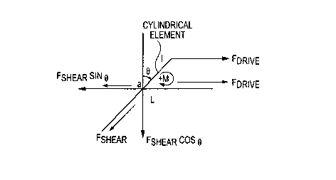
aligned in the direction of the flow as illustrated in the diagram of FIGURES
1-3.
Specifically, FIGURE 1 illustrates a force diagram with a turning moment M
resulting
from application of shear forces and drive forces imparted upon a nanotube or
nanofiber
by a matrix material flowing in a laminar fashion. FIGURE 2 is a velocity
profile of a
flowing material when such flow is laminar. Typically, the velocity profile of
such flow is
parabolic in shape. That is, velocity vectors corresponding to velocities at
different
locations across a flow cross-section, generally trace a curve that is
parabolic in shape.
As will be understood, flow streams within the interior or mid-region of a
flow channel or
profile will typically exhibit a greater velocity than flow streams along the
edges or end
regions of the channel or profile. FIGURE 3 illustrates attainment of a zero
turning
moment by a nanotube or nanofiber once the nanotube or nanofiber is aligned
within
the flow. In view of this phenomenon, the preferred embodiment materials and
24
CA 02654061 2008-12-01
WO 2008/060336 PCT/US2007/013406
processes utilize nanostructures that have aspect ratios greater than 1.0,
thereby
facilitating their alignment in the direction of flow.
[0090] FIGURE 4 is a schematic illustration showing progression of (i)
reduction of
inclusions or porosity voids, and (ii) dispersing and alignment of carbon
nanofibers
dispersed in a laminar flowing matrix material. During early phases of the
flowing
system, such as depicted in the lower region of FIGURE 4, the random
orientation of
the carbon nanofibers is apparent. As the flowing system continues, the carbon
nanofibers begin to partially align as shown. After a relatively short period
of time, the
carbon nanofibers become fully aligned. Similarly, the relative size of any
inclusions or
porosity voids also tends to become smaller, as shown in FIGURE 4. This is
another
surprising benefit associated with the present invention. Although not wishing
to be
bound to any particular theory, it is believed that inducing and maintaining a
laminar
flow, particularly as compared to a turbulent flow, promotes the elimination
or at least
reduction in the number and severity of inclusions and voids in the system.
[0091] As noted, inducing laminar flow of the combined matrix material and
nanostructures dispersed therein, causes dispersing and alignment of the
nanostructures within the matrix material. However, in certain applications,
it may be
desired to perform a secondary operation to further promote alignment of the
nanostructures. In the case of viscoelastic and plastic flow, there is
considerable
microscopic shearing and slippage between the flow planes due to the
differentials in
the velocity profile of the flowing material as is the case during fiber glass
forming, wire
drawing operations and rolling operations, e.g., sheet metal rolling. This was
demonstrated in testing results described herein for the case of glass
composite
material fibers. Generally, 0.125 inch diameter tips were used to drip a
slurry of molten
flowable glass matrix material comprising nanotubes and nanofibers dispersed
therein,
which was quickly pulled or drawn to a diameter of 7-10 pm over a distance of
less than
one inch. This created very large velocity differentials and considerable
shear in the
flow and as such, readily further dispersed and aligned the
nanotubes/nanofibers in the
glass fibers.
Secondary Operations for Improved Dispersing
CA 02654061 2008-12-01
WO 2008/060336 PCT/US2007/013406
[0092] Once a fiber is drawn, porosity voids, inclusions or agglomerations may
exist
within the fiber. However, these will not be larger than the diameter of the
fiber,
otherwise this would cause the fiber to break or otherwise sever. Therefore,
in the case
of a fiber that is 7-10 pm in diameter, the largest inclusion and/or
agglomeration must be
smaller than the corresponding fiber diameter. The length of the inclusions,
however, is
not limited and could in theory, be extremely long. In accordance with the
present
invention, this problem can be remedied by chopping the fibers into discrete
units
having appropriate lengths, remixing them, heating the resulting collection to
form a
flowable material, and redrawing the material into fibers or casting the blend
into bars or
ingots for later processing into final products. An appropriate length for the
chopped
fibers is preferably a length that is greater than the length of the
nanostructures
incorporated into material. For example, if fibers are formed comprising
nanotubes
which are 200 to 300 microns in length, chopping the fibers into lengths
shorter than this
range would be undesirable. Otherwise, the nanotubes themselves would be
severed.
This process is particularly preferred for glass, fused silicas and metal
powders.
[0093] Certain processing applications or production operations involve a feed
material that is merely deformed, e.g. via plastic deformation, instead of
undergoing a
laminar flow. Examples of such applications are cold rolling or wire drawing
of a metal
bar to form a thin sheet or wire, as desired. One wishing to incorporate and
align
nanostructures in the product of such an operation may encounter difficulty in
achieving
sufficient dispersion and alignment of the nanostructures within the metal
matrix. To
overcome this difficulty, the feed material, e.g. metal in the present
example, is heated
to a flowable or molten state, and then mixed or otherwise combined with the
nanostructures. The resulting blend is then flowed, preferably a laminar flow,
to
disperse and align the nanostructures within the metal matrix. The resulting
composite
feed material is then cooled to retain the aligned orientation of the
nanostructures. The
resulting composite material is then used as feed for the deforming operation
such as
cold rolling or wire drawing. In this fashion, products of a wire drawing
operation can
readily be provided that comprise effective amounts of aligned nanostructures.
Similarly, products of a cold rolling operation such as thin metal sheets or
foils can be
produced that contain effective amounts of aligned nanostructures.
26
CA 02654061 2008-12-01
WO 2008/060336 PCT/US2007/013406
[0094] FIGURE 19 schematically illustrates a roller and wire drawing process
for
producing wires or sheets of material comprising aligned nanotubes as
described
herein. An assembly 700 comprising a plurality of rollers 710 receives a feed
material
720 that includes a collection of oriented and aligned nanostructures 730
dispersed in a
matrix material 740. As the feed material 720 progresses past the opposing
pairs of
rollers 710 in the direction of arrow A, the material 720 is deformed into a
desired shape
or dimension.
[0095] FIGURE 20 is a schematic depiction of orientation and alignment of
nanostructures occurring as a result of laminar flow between two parallel, or
substantially parallel, plates or walls. Assembly 800 comprises a first plate
810 and a
second plate spaced from the first plate and generally parallel thereto. A
flowable
material 830 comprising nanostructures 840 dispersed in a matrix material 850
is
caused to flow in a laminar fashion (note the parabolic shape of the velocity
profile),
between the plates or walls 810 and 820. It will be appreciated that the width
W and
depth D of the flow channel can be tailored as desired by the artisan or as
dictated by
the application. For example, a wide sheet of relatively large dimensions
having
nanostructures dispersed throughout its thickness and aligned to be generally
parallel
with the plane of the sheet and further aligned along an axis of the sheet,
can be formed
by flowing such material through a channel as shown in FIGURE 20, in which the
ratio
of W to D is relatively large.
[0096] FIGURE 21 is a schematic depiction of an assembly 900 for extruding
material through a die. Specifically, in the assembly 900, material 980
comprising
nanostructures 950 in a matrix material 960 is introduced into a container or
receiving
unit 910. The receiving unit 910 includes a displaceable piston 920 and an
exit port
940. Preferably, the unit 910 defines a narrowed region or channel 930
upstream of the
exit port 940. It will be appreciated that an extrusion die may be used at the
exit port
940. Upon movement or translation of the piston 920 in the direction of arrow
B, the
material 980 is caused to flow through the channel 930 and out of the exit
port 940. As
explained herein, it is preferred that the conditions of flow within the
channel 930 are
selected such that the flow in that region is laminar. Preferably, a parabolic
velocity
profile for that flow is established such as designated by 970.
27
CA 02654061 2008-12-01
WO 2008/060336 PCT/US2007/013406
Feedstock Preparation
[0097] Mixing nanotubes and/or nanofibers with dry glass frit and milling the
mixture
for an extended period of time under inert conditions using nitrogen or argon
gas serves
to disperse the nanotubes and/or nanofibers in the mix and protect them from
oxidation
by shrouding them with the inert atmosphere. Removing oxygen from the
immediate
surroundings of the carbon nanotubes/nanofibers is critical to preventing
their
deterioration while processing at high temperatures.
Glass Fiber Drawinp Process
[0098] . As noted, in certain instances or applications, it may be preferred
to utilize a
glass drawing operation to further promote alignment of the nanostructures
within the
matrix material. A preferred glass drawing facility produces continuous
lengths of glass
fibers, preferably 7-10 pm in diameter. The glass is heated to its melting
temperature.
For E glass, the melt temperature is about 1200'C. The input material in this
process is
solid E glass marbles (or frit) of different formulations depending upon the
end use
application. The molten glass is gravity fed into a plurality of dies such as
a platinum
bushing with 200 tips, each 1.8 mm in diameter as shown in FIGURE 5.
Individual
fibers are pulled from each tip and the diameter of the glass is attenuated
from the 1.8
mm starting point to the final mean diameter of the fibers, which can be for
example, 7-
pm.
Testing Results
[0099] Preliminary results indicate that the proposed methodology for
reinforcing a
matrix material such as glass microfibers, with a nanostructure material such
as carbon
nanotubes/carbon nanofibers, is indeed viable.
[00100] The investigations conducted were not controlled in that the ultimate
and
exact concentration of the carbon nanofibers in the glass filaments was not
known.
However, the concentration was estimated, and this study indicates the
significant
advantages provided by the present invention. A 20 gram E glass/carbon
nanofiber
coupon containing 40% carbon nanofibers was dropped in the center of the
melter of a
glass drawing tower which contained 40 pounds of undisturbed E glass. Due to
the
difference in the specific gravities of the coupon and the pure E glass and
also due to
28
CA 02654061 2008-12-01
WO 2008/060336 PCT/US2007/013406
the lack of agitation, the carbon nanofibers did not mix uniformly with the
undisturbed
glass in the melter.
[00101] The resulting molten material comprising E glass as the matrix
material and
carbon nanotubes and carbon nanofibers as the high aspect ratio nanostructures
dispersed therein, flowed in a laminar fashion to a glass fiber bushing tip
assembly, as
previously described and shown in FIGURE 5. The flowing mass was further
subjected
to a pulling or drawing operation to thereby form the fibers of the glass
composite
material.
[00102] The drawn filaments were continuous and their diameter was on the
order of
30-40 pm. The filament's diameters were larger than the normal diameter
because the
fibers were not pulled and wound to a smaller diameter. It is estimated that
in a best
case scenario, the concentration of the carbon nanofibers in the glass
filaments was
fairly low, perhaps on the order of about 0.25% to about 0.5%. This was
ascertained
from the fact that the filaments did not exhibit a change in color to the
naked eye.
However, the areas of the filaments containing the carbon nanofibers
fluoresced in the
gold color region when exposed to UV long wave light (354 nm) as is shown in
FIGURE
6. That figure also validates the expected non-uniform distribution of the
carbon
nanofibers between the individual filaments due to the poor mixing process.
[00103] Optical tests conducted on the bulk carbon nanotube material
demonstrated a
lack of fluorescence in the visible spectrum (the infrared band was not
explored). This
behavior, i.e., the lack of fluorescence in the bulk and strong fluorescence
when
dispersed in the glass filaments, is consistent with the behavior of bulk and
nano silicon
which has strong fluorescence in the dispersed nano-state and none in the bulk
state.
[00104] The carbon nanofibers used in the investigations were multi-wall
carbon
nanofibers shown in FIGURE 7. FIGURE 7 is a scanning electron microscope (SEM)
micrograph of the multi-wall carbon nanofibers taken at 3.0 KV, 13.2 mm x 20.0
K. The
multi-wall carbon nanofibers used were obtained from Pyrograf@ Products, Inc.,
a
subsidiary of Applied Sciences, Inc. of Cedarville, Ohio. Table 2 lists their
nominal
properties after heat treating:
Table 2
Characteristic or Pro ert Value
29
CA 02654061 2008-12-01
WO 2008/060336 PCT/US2007/013406
Mean diameter: 100-200nm
Mean length 200-300 pm
Tensile strength Approximately 7-15 GPa
Tensile Modulus 600 GPa
Density 2.1 cm3
Optical Properties Black none fluorescent in bulk
Electrical Resistively 55 Microohm/cm
Thermal Conductivity 1950 W/m-K
[00105] Preliminary analysis of the hybrid fibers indicate that the carbon
nanofibers
were well dispersed and aligned along the axis of the E glass filaments as is
shown in
FIGURE 8. FIGURE 8 is an SEM micrograph taken at 3.0 KV, 13.4 mm x 9.00 K.
[00106] Pull tests were conducted on a population of 20 tows of glass
composite
fibers each containing approximately 200 filaments. The tests indicated that
there is a
significant increase in the tensile strength of the fibers containing the
carbon nanofibers.
As evident from FIGURE 9, breaking load of the composite fiber increased as
the
concentration of the carbon nanotubes increased. The results of the pull tests
are
displayed in FIGURE 9, and indicate that the strength of the fibers increased
by nearly
60% and in some cases doubled.
[00107] The fracture surfaces of the hybrid fibers were considerably different
from that
exhibited by normal E glass fibers. FIGURE 10 shows that the brittle fracture
surface
shown on the left in the image is considerably modified due to the presence of
the
carbon nanofibers in the fibers on the right. FIGURE 10 is an SEM micrograph
(left)
taken at 3.0 KV, 14.7 mm x 1.00 K; and an SEM micrograph (right) taken at 3.0
KV, 6.8
mm x 6.00 K.
[00108] Close inspection of the break surfaces showed that the carbon
nanofibers
were indeed well dispersed and aligned along the length of the axis of the
fibers as
shown in FIGURE 11. FIGURE 11 is an SEM micrograph (left) taken at 3.0 KV,
13.4
mm x 8.00 K; and an SEM micrograph (right) taken at 3.0 KV, 13.4 mm x 18.0 K.
Additional Embodiments
[00109] As noted in the reported previous work by one of the present
inventors,
concerning composite materials using boron nitride nanotubes, it has been
demonstrated that significant improvement in the strength of glass fuel cell
seal
materials can be obtained by incorporating 4% of boron nitride nanotubes in
the glass
CA 02654061 2008-12-01
WO 2008/060336 PCT/US2007/013406
matrix. Results indicate that the strength nearly doubled and there was a 40%
improvement in the fracture toughness of the matrix by the addition of
nanotubes as
indicated in FIGURES 12 and 13. The length of the boron nitride nanotube in
those
studies is on the order of 200-300 pm. Specifically, FIGURE 12 is a graph of
fracture
toughness of a commercially available glass G18 used in those studies and that
G18
glass reinforced with boron nitride nanotubes (BN NT). Fracture toughness is
expressed as K1c[MPa m0-5]. FIGURE 13 is a detailed view illustrating Weibull
strength
distribution of those materials. Weibull strength distribution is Inln[1/(1-
F)]. M is the
Weibull modulus and Se is the characteristic length. These results indicate
the
significant physical properties which are attainable of composite glass,
ceramic, and/or
metal materials using boron nitride nanostructures in accordance with the
present
invention.
[00110] All referenced patents, patent applications, and documents referenced
herein
are incorporated herein in their entirety.
[00111] The present invention has been described with reference to the
preferred
embodiments. Obviously, modifications and alterations will occur to others
upon
reading and understanding the preceding detailed description. It is intended
that the
exemplary embodiment be construed as including all such modifications.and
alterations
insofar as they come within the scope of the appended claims or the
equivalents
thereof.
31