Language selection

Search

Patent 2654103 Summary

Third-party information liability

Some of the information on this Web page has been provided by external sources. The Government of Canada is not responsible for the accuracy, reliability or currency of the information supplied by external sources. Users wishing to rely upon this information should consult directly with the source of the information. Content provided by external sources is not subject to official languages, privacy and accessibility requirements.

Claims and Abstract availability

Any discrepancies in the text and image of the Claims and Abstract are due to differing posting times. Text of the Claims and Abstract are posted:

  • At the time the application is open to public inspection;
  • At the time of issue of the patent (grant).
(12) Patent Application: (11) CA 2654103
(54) English Title: A LIQUID DISTRIBUTOR VALVE
(54) French Title: VALVE DE DISTRIBUTEUR DE LIQUIDE
Status: Deemed Abandoned and Beyond the Period of Reinstatement - Pending Response to Notice of Disregarded Communication
Bibliographic Data
(51) International Patent Classification (IPC):
  • F16K 31/04 (2006.01)
  • F16K 43/00 (2006.01)
(72) Inventors :
  • TORAL GOMEZ, ALEX (Spain)
  • IBANEZ SAPINA, MIGUEL (Spain)
  • SALGADO SALICHS, JOSEP (Spain)
(73) Owners :
  • VALVULES I RACORDS CANOVELLES, S.A.
(71) Applicants :
  • VALVULES I RACORDS CANOVELLES, S.A. (Spain)
(74) Agent: ROBIC AGENCE PI S.E.C./ROBIC IP AGENCY LP
(74) Associate agent:
(45) Issued:
(22) Filed Date: 2009-02-13
(41) Open to Public Inspection: 2009-09-30
Availability of licence: N/A
Dedicated to the Public: N/A
(25) Language of filing: English

Patent Cooperation Treaty (PCT): No

(30) Application Priority Data:
Application No. Country/Territory Date
ES 200800631 U (Spain) 2008-03-31

Abstracts

English Abstract


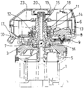
This liquid distributor valve comprises a
compartmented base body (1) being provided with a cover
(3) and with several outlets (2) and one inlet (4), a
rotatable obturator bell (5) being innerly arranged and
having a shaft (7) projecting through said cover (3) and
being governed by an externally arranged electronic
control (6) being made up by an independent assembly
being adapted to be fitted onto the base body (1). This
valve is characterised in that the actuation on the shaft
(7) of the obturator bell from the gearmotor (8) of the
externally arranged electronic control (6) is carried out
through a pinion (9) being driven by the shaft of the
gearmotor (8) and enmeshed with a gear wheel (10) being
linked to the shaft (7) of the obturator bell (5). The
linking between the gear wheel (10) and the shaft (7) of
the obturator bell (5) is accomplished by means of a
tubular body (11) having an external thread (12) matching
the thread (13) being provided in the inside of the neck
(14) forming an extension of the gear wheel (10).


Claims

Note: Claims are shown in the official language in which they were submitted.

5
CLAIMS
1. A liquid distributor valve comprising a
compartmented base body (1) being provided with a cover
(3) and with several outlets (2) and one inlet (4), a
rotatable obturator bell (5) being innerly arranged and
having a shaft (7) projecting through said cover (3) and
being governed by an externally arranged electronic
control (6) being made up by an independent assembly
being adapted to be fitted onto the base body (1);
characterised in that the actuation on the shaft (7) of
the obturator bell from the gearmotor (8) of the
externally arranged electronic control (6) is carried out
through a pinion (9) being driven by the shaft of the
gearmotor (8) and enmeshed with a gear wheel (10) being
linked to the shaft (7) of the obturator bell (5).
2. A liquid distributor valve, as per claim 1,
characterised in that the linking between the gear wheel
(10) and the shaft (7) of the obturator bell (5) is
accomplished by means of a tubular body (11) having an
external thread (12) matching the thread (13) being
provided in the inside of a neck (14) forming an
extension of the gear wheel (10), said tubular body (11)
being fitted onto a tubular spindle (15) being linked to
the shaft (7) of the obturator bell (5).
3. A liquid distributor valve, as per claim 2,
characterised in that a boss (16) being arranged
underneath the gear wheel (10) and the tubular body (11)
is fitted onto the tubular spindle (15).
4. A liquid distributor valve, as per claim 1,
characterised in that the assembly making up the
externally arranged electronic control (6) comprises a
base (17) and a cap (18), this latter having a top
opening (19) allowing to have access to the components of
the electronic control (6), said opening being adapted to
be closed by means of a stopper (20).

Description

Note: Descriptions are shown in the official language in which they were submitted.


-- - - ---- ---- -------
CA 02654103 2009-02-13
1
DESCRIPTION
OBJECT OF THE INVENTION
A liquid distributor valve.
BACKGROUND OF THE INVENTION
Liquid distributor valves are known which comprise a
radially compartmented base body having several outlets
and a lateral inlet, a rotatable obturator bell being
interposed between said outlets and said inlet and being
provided with an upperly arranged shaft projecting
through the top cover of said body and being actuated by
a manual or electronic, externally arranged control.
This type of electronically actuated valves has the
drawback that the electronic control portion and the
mechanical portion acting within the base body are linked
to each other thus forming an assembly. This represents a
substantial drawback when there is a need to repair the
electronic portion or the mechanical portion, since the
assembly being made up by them must then be disassembled
in order to replace or repair the affected components.
It has been attempted to obviate said drawbacks by
forming the externally arranged electronic control as per
a totally independent assembly being adapted to be
removably fitted onto the base body.
The means being used to actuate the shaft of the
obturator bell from the externally arranged electronic
control, and namely from the gearmotor forming part of
said electronic control, are nevertheless complex in
their mechanical make-up.
SUMMARY OF THE INVENTION
This invention has as its object a liquid
distributor valve having a simplified and compact make-
up. A characterising feature lies in the actuation on the
shaft of the obturator bell from the gearmotor of the
externally arranged electronic control through a pinion
being driven by the gearmotor shaft and enmeshed with a

CA 02654103 2009-02-13
2
gear wheel being linked to the shaft of the obturator
bell.
This linking between the gear wheel and the shaft of
the obturator bell is accomplished by means of a tubular
body having an external thread matching the thread being
provided in the inside of a neck forming an extension of
the gear wheel, said tubular body being fitted onto a
tubular spindle being linked to the shaft of the
obturator bell.
These and other characterising features will be best
made apparent by the following detailed description whose
understanding will be made easier by the accompanying two
sheets of drawings showing a practical embodiment being
cited only by way of example not limiting the scope of
the present invention.
DESCRIPTION OF THE DRAWINGS
In the drawings:
Fig. 1 illustrates in a perspective view the
distributor valve being the object of the invention;
Fig. 2 depicts said valve in a sectional elevation;
and
Fig. 3 shows in a perspective view the assembly
making up the externally arranged electronic control with
its basic components shown in an exploded arrangement.
DETAILED DESCRIPTION
According to the drawings this liquid distributor
valve comprises a compartmented base body (1) having
several outlets (2), a cover (3) being fastened onto said
base body, this latter having a lateral inlet (4) for the
liquid.
Between the body (1) and the cover (3) a rotatable
obturator bell (5) is arranged which is governed by an
electronic control (6) being superimposed on the cover
(3), the shaft (7) corresponding to the obturator bell

CA 02654103 2009-02-13
3
(5) projecting through a central orifice of said cover
(Fig. 2).
A characterising feature of this distributor valve
lies in the fact of acting on the shaft (7) of the
obturator bell from the gearmotor (8) of the electronic
control (6) through a pinion (9) being driven by the
shaft of the gearmotor (8) and enmeshed with a gear wheel
(10) being linked to the shaft (7) of the obturator bell.
This linking between the gear wheel (10) and the
shaft (7) is accomplished by means of a tubular body (11)
having an external thread (12) matching the thread (13)
being provided in the inside of a neck (14) forming an
extension of the gear wheel (10), said tubular body (11)
being fitted onto a tubular spindle (15) being linked to
the shaft (7) of the obturator bell, a boss (16) being
arranged underneath the gear wheel and the tubular body
and fitted onto the tubular spindle (15).
The assembly making up the electronic control (6)
comprises a base (17) and a cap (18) having a top opening
(19) allowing to have access to the components of the
control, said opening being adapted to be closed with a
stopper (20).
With reference numbers (21, 22) the microswitches
are denoted which are linked to the catch being operable
for stabilising the different positions of the obturator
bell (5), and reference number (23) denotes the
electronics board with the printed circuit.
The reduced height dimensions of the electronic
control (6) and the compartmented body (1) determine a
compact assembly.
The invention can within its essentiality be put
into practice in other embodiments only in detail
differing from the one having been described above only
by way of example, said other embodiments also falling
within the scope of the protection being sought. This

CA 02654103 2009-02-13
4
liquid distributor valve can hence be manufactured in any
shape and size, with the best suited means and materials
and with the most convenient accessories, and its
integrating elements can be replaced with others being
technically equivalent, all this falling within the
spirit of the appended claims.

Representative Drawing
A single figure which represents the drawing illustrating the invention.
Administrative Status

2024-08-01:As part of the Next Generation Patents (NGP) transition, the Canadian Patents Database (CPD) now contains a more detailed Event History, which replicates the Event Log of our new back-office solution.

Please note that "Inactive:" events refers to events no longer in use in our new back-office solution.

For a clearer understanding of the status of the application/patent presented on this page, the site Disclaimer , as well as the definitions for Patent , Event History , Maintenance Fee  and Payment History  should be consulted.

Event History

Description Date
Application Not Reinstated by Deadline 2015-02-13
Time Limit for Reversal Expired 2015-02-13
Inactive: Abandon-RFE+Late fee unpaid-Correspondence sent 2014-02-13
Deemed Abandoned - Failure to Respond to Maintenance Fee Notice 2014-02-13
Maintenance Request Received 2013-02-06
Inactive: Filing certificate - No RFE (English) 2011-03-15
Inactive: Office letter 2011-03-15
Correct Applicant Requirements Determined Compliant 2011-03-15
Inactive: Correspondence - MF 2010-08-10
Inactive: Cover page published 2009-10-09
Application Published (Open to Public Inspection) 2009-09-30
Inactive: IPC assigned 2009-08-31
Inactive: First IPC assigned 2009-08-31
Inactive: IPC assigned 2009-08-31
Small Entity Declaration Determined Compliant 2009-05-07
Small Entity Declaration Request Received 2009-05-07
Inactive: Correspondence - Formalities 2009-03-31
Inactive: Office letter 2009-03-17
Application Received - Regular National 2009-03-13
Letter Sent 2009-03-13
Inactive: Filing certificate - No RFE (English) 2009-03-13
Small Entity Declaration Determined Compliant 2009-02-13

Abandonment History

Abandonment Date Reason Reinstatement Date
2014-02-13

Maintenance Fee

The last payment was received on 2013-02-06

Note : If the full payment has not been received on or before the date indicated, a further fee may be required which may be one of the following

  • the reinstatement fee;
  • the late payment fee; or
  • additional fee to reverse deemed expiry.

Patent fees are adjusted on the 1st of January every year. The amounts above are the current amounts if received by December 31 of the current year.
Please refer to the CIPO Patent Fees web page to see all current fee amounts.

Fee History

Fee Type Anniversary Year Due Date Paid Date
Application fee - small 2009-02-13
Registration of a document 2009-02-13
MF (application, 2nd anniv.) - small 02 2011-02-14 2011-01-14
MF (application, 3rd anniv.) - small 03 2012-02-13 2012-02-01
MF (application, 4th anniv.) - small 04 2013-02-13 2013-02-06
Owners on Record

Note: Records showing the ownership history in alphabetical order.

Current Owners on Record
VALVULES I RACORDS CANOVELLES, S.A.
Past Owners on Record
ALEX TORAL GOMEZ
JOSEP SALGADO SALICHS
MIGUEL IBANEZ SAPINA
Past Owners that do not appear in the "Owners on Record" listing will appear in other documentation within the application.
Documents

To view selected files, please enter reCAPTCHA code :


To view images, click a link in the Document Description column. To download the documents, select one or more checkboxes in the first column and then click the "Download Selected in PDF format (Zip Archive)" or the "Download Selected as Single PDF" button.

List of published and non-published patent-specific documents on the CPD .

If you have any difficulty accessing content, you can call the Client Service Centre at 1-866-997-1936 or send them an e-mail at CIPO Client Service Centre.


Document
Description 
Date
(yyyy-mm-dd) 
Number of pages   Size of Image (KB) 
Abstract 2009-02-12 1 25
Description 2009-02-12 4 123
Claims 2009-02-12 1 41
Drawings 2009-02-12 2 89
Representative drawing 2009-09-08 1 21
Courtesy - Certificate of registration (related document(s)) 2009-03-12 1 103
Filing Certificate (English) 2009-03-12 1 157
Reminder of maintenance fee due 2010-10-13 1 113
Filing Certificate (English) 2011-03-14 1 166
Reminder - Request for Examination 2013-10-15 1 125
Courtesy - Abandonment Letter (Request for Examination) 2014-04-09 1 164
Courtesy - Abandonment Letter (Maintenance Fee) 2014-04-09 1 172
Correspondence 2009-03-12 1 14
Correspondence 2009-03-30 3 126
Correspondence 2009-05-06 2 70
Correspondence 2010-08-09 1 45
Correspondence 2010-10-13 1 38
Fees 2011-01-13 1 52
Correspondence 2011-03-14 1 22
Correspondence 2011-03-14 1 42
Fees 2012-01-31 1 55
Fees 2013-02-05 1 55