Note: Descriptions are shown in the official language in which they were submitted.
CA 02654305 2008-12-02
WO 2007/142537 PCT/NZ2007/000138
"IMPROVEMENTS RELATING TO CONTROL OF MARINE VESSELS"
FIELD OF THE INVENTION
The invention relates to control of waterjet-propelled marine vessels and in
particular, but not limited to, dynamic control of a multiple waterjet marine
vessel.
BACKGROUND TO THE INVENTION
Dynamic positioning refers generically to an automated method of maintaining a
vessel at a fixed location without mooring or anchoring the vessel. Systems
are
currently available that employ dynamic positioning on large vessels, such as
drilling ships. These systems are typically used to maintain vessel station in
deep
water often for extended periods, over a fixed point on the seabed. They are
complex and typically utilise multiple purpose-provided drop down azimuth
thrusters.
US patent 5,491,636 discloses a dynamic positioning system which utilises a
steerable bow thruster, such as a trolling motor, to dynamically maintain a
boat at a
selected anchoring point.
It is an object of the present invention to provide systems and methods that
provide
either or both of dynamic positioning and dynamic velocity control for a
waterjet-
propelled marine vessel and/or that at least provide the public with a useful
choice.
SUMMARY OF THE INVENTION
In a first aspect, the present invention broadly consists of a dynamic control
system
for a marine vessel having two or more waterjet units as the primary
propulsion
system of the vessel, for maintaining vessel position or velocity when in a
dynamic
control mode, comprising:
a position or velocity indicator to indicate vessel position or velocity or
deviations in vessel position or velocity;
CA 02654305 2008-12-02
WO 2007/142537 PCT/NZ2007/000138
-2-
a heading indicator to indicate vessel heading or yaw rate or deviations in
vessel heading or yaw rate; and
a controller to control the operation of the waterjet units to substantially
maintain the vessel position or velocity, and vessel heading or yaw rate when
the
dynamic control mode is enabled.
More particularly, the invention broadly consists of a dynamic control system
for a
marine vessel propelled by two or more waterjet units comprising:
an input means for enabling a dynamic control mode and setting a
commanded vessel position or velocity;
a position or velocity indicator to indicate vessel position or velocity or
deviations in vessel position or velocity;
a heading indicator to indicate vessel heading or yaw rate or deviations in
vessel heading or yaw rate; and
a controller arranged to monitor for position or velocity deviations relative
to
a commanded vessel position or velocity and for heading or yaw rate deviations
relative to a commanded vessel heading or yaw rate and to control the
operation of
the waterjet units to minimise position or velocity error and heading or yaw
rate
error when the dynamic control mode is enabled.
Typically the desired vessel position or velocity and the desired vessel
heading or
yaw rate are a position or velocity and a heading or yaw rate of the vessel at
the
time the dynamic control system is enabled (hereinafter often referred to as a
current position or velocity and heading or yaw rate). The input means may be
one
or more buttons, switches, or the like for enabling the dynamic control mode
and
setting the current vessel position and heading or velocity and heading or yaw
rate
as the commanded position and heading or velocity and heading or yaw rate.
Alternatively or additionally the input means may enable input of a commanded
position and/or heading, or velocity and/or heading or yaw rate which is
different
from the current vessel position and heading or velocity and heading and/or
yaw
rate.
CA 02654305 2008-12-02
WO 2007/142537 PCT/NZ2007/000138
-3-
Preferably the commanded vessel position and heading or velocity and heading
or
yaw rate, may be subsequently altered while a dynamic control mode is enabled,
for
example using a control device such as a joystick, a helm wheel , and/or
throttle
lever(s).
The position or velocity indicator means may indicate an absolute vessel
ground
position or velocity, via for example a satellite-based positioning system
such as the
Global Positioning System (GPS) or differential GPS (DGPS). Alternatively, the
position or velocity indicator may indicate relative position or velocity by
indicating
deviations in vessel position or velocity relative to the commanded vessel
reference
position or velocity, via one or more sensors arranged to indicate vessel
motion
relative to an initial position or velocity. Alternatively again the position
or velocity
indicator may indicate vessel position or velocity relative to another object
which
may be stationary or moving, such as relative to a dock or berth or relative
to
another stationary or moving surface or submarine vessel or relative to a
diver
moving under water, via for example a radar, acoustic, or laser range finding
technique.
The heading indicator may indicate absolute heading via a compass, or relative
heading by indicating changes in heading relative to a commanded vessel
heading
via a heading sensor sensitive to relative changes in vessel heading. A yaw
rate
sensor indicates changes in yaw rate relative to a commanded yaw rate.
Typically the controller is arranged to controllably actuate the engine
throttles and
steering deflectors and reverse ducts of the waterjet units. The controller is
preferably arranged to actuate the steering deflectors of the waterjet units
in
synchronism, and the reverse ducts either in synchronism or differentially.
In a second aspect, the invention broadly consists of a computer-implemented
method for dynamically controlling a marine vessel propelled by two or more
waterjet units comprising the steps of:
(a) determining a commanded vessel position or velocity and heading or yaw
rate;
CA 02654305 2008-12-02
WO 2007/142537 PCT/NZ2007/000138
-4-
(b) determining a current vessel position or velocity using a position or
velocity determining means;
(c) determining a current vessel heading or yaw rate using a heading or yaw
rate determining means; and
controlling waterjet units, which are the primary propulsion system of the
vessel, to
substantially maintain the commanded vessel position or velocity, and vessel
heading or yaw rate.
The commanded vessel position or velocity and heading or yaw rate may be the.
position and heading or velocity and heading or yaw rate at the time the
dynamic
control system is enabled, or a different vessel position and heading or
velocity and
heading or yaw rate which is input to a control system as the commanded
position
and heading or velocity and heading or yaw rate at the commencement of dynamic
control or subsequently.
More particularly, the present invention broadly consists of a computer-
implemented method for dynamically controlling a marine vessel propelled by
two
or more waterjet units comprising the steps of:
(a) receiving a commanded vessel position or velocity, and a commanded
vessel heading or:=yaw rate
(b) determining the current vessel position or velocity using a position or
velocity determining means;
(c) determining the current vessel heading or yaw rate using a heading or
yaw rate determining means;
(d) calculating a position or velocity error based on the difference between
the commanded vessel position or velocity, and current vessel position or
velocity;
(e) calculating a heading or yaw rate error based on the difference between
the commanded vessel heading or yaw rate and current vessel heading or
yaw rate; and
CA 02654305 2008-12-02
WO 2007/142537 PCT/NZ2007/000138
-5-
(f) controlling the waterjet units to minimise the position or velocity error,
and heading or yaw rate error.
The step of calculating a position or velocity error may comprise calculating
a
difference relative to an absolute vessel position or velocity or relative to
an initial
vessel position or velocity. The step of calculating a heading or yaw rate
error may
comprise calculating a heading or yaw rate error relative to an absolute
heading or
yaw rate or relative to an initial heading or yaw rate.
The invention may also be said broadly to consist in the parts, elements and
features
referred to or indicated in the specification of the application, individually
or
collectively, and any or all combinations of any two or more said parts,
elements or
features. Where specific integers are mentioned herein which have known
equivalents in the art to which this invention relates, such known equivalents
are
deemed to be incorporated herein as if individually set forth.
The term `comprising' as used in this specification means `consisting at least
in part
of, that is to say when interpreting statements in this specification which
include
that term, the features, prefaced by that term in each statement, all need to
be
present but other features can also be present.
In this specification;' the term `vessel' is intended to include boats such as
smaller
pleasure runabouts and other boats, larger launches whether mono-hulls or
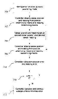
multi-
hulls, and larger vessels.
BRIEF DESCRIPTION OF THE FIGURES
Various forms of the systems and methods of the invention will now be
described
with reference to the accompanying figures in which:
CA 02654305 2008-12-02
WO 2007/142537 PCT/NZ2007/000138
-6-
Figure 1 shows a schematic of one example form of a dynamic positioning
system;
Figure 2 shows a process flow for an example dynamic positioning method;
Figure 3 shows a schematic of one example form of a dynamic velocity
control system;
Figure 4 shows a process flow for an example dynamic velocity control
method;
Figure 5 shows the six basic manoeuvres of a twin waterjet-propelled vessel;
Figure 6 shows a sideways translation of a twin waterjet-propelled vessel;
and
Figure 7 shows a block diagram showing one example dynamic velocity
control system.
DETAILED DESCRIPTION OF THE EMBODIMENTS
The invention is now described with reference to marine vessels that are
propelled
with two waterjet units at the stern of the vessel ('twin waterjet vessel').
The
systems and methods of the invention may also be used on waterjet vessels
propelled by more than two waterjet units, such as three or four waterjet
units for
example.
Dynamic Positioning System
Referring to Figure 1, a schematic arrangement of one embodiment of a dynamic
positioning system of the present invention is shown. The system includes a
controller 1,00, such as a microprocessor, microcontroller, programmable logic
controller (PLC) or the like programmed to receive and process data so as to
dynamically maintain the heading and position of the vessel when the dynamic
CA 02654305 2008-12-02
WO 2007/142537 PCT/NZ2007/000138
-7-
positioning mode is enabled. The controller 100 may be a stand-alone or
dedicated
controller for dynamic positioning or preferably is incorporated into an
existing
vessel controller. In one form, the controller 100 is a plug-in module that is
connected to a network, such as a Controller Area Network (CAN), in the
waterjet
vessel.
The controller 100 controls port and starboard waterjet units 102 which are
the
primary propulsion systems for the vessel. Where more than two waterjet units
are
provided as referred to previously, the controller 100 may be adapted to
provide
dynamic control to at least one port waterjet unit and one starboard waterjet
unit.
Each waterjet unit 102 comprises a housing containing a pumping unit 104
driven
by an engine 106 through a driveshaft 108. Each waterjet unit also includes a
steering deflector 110 and a reverse duct 112. In the form illustrated, each
reverse
duct 112 is of a type that features split passages to improve reverse thrust.
The
split-passage reverse duct 112 also affects the steering thrust to port and
starboard
when the duct is lowered into the jet stream. The steering deflectors 110
pivot
about generally vertical axes 114 while the reverse ducts 112 pivot about
generally
horizontal axes 116, independently of the steering deflectors. The engine
throttle,
steering deflector and reverse duct of each unit is actuated by signals
received from
the actuation modules 118 and 120 through control input ports 122, 124 and 126
respectively. The actuation modules 118 and 120 are in turn controlled by the
controller 100.
The controller 100 receives a number of inputs to effect vessel control. One
input
comes from one or more vessel control devices 128, such as one or more
joysticks,
helm controls, throttle levers or the like. The vessel control device(s) 128
is used by
a helmsperson to manually operate the vessel.
The controller 100 also receives input from a dynamic control input means 130
which may be operated to enable a dynamic control mode, such as one or more
CA 02654305 2008-12-02
WO 2007/142537 PCT/NZ2007/000138
-8-
buttons, switches, keypads or the like. The dynamic control input device 130
is
used by the helmsperson to enable a dynamic control mode, including or
specifically a dynamic positioning mode in which the controller controls the
waterjet units of the vessel to maintain the vessel position and vessel
heading. The
operation of the controller in the dynamic positioning mode will be described
in
detail.
The controller 100 has inputs indicative of the vessel position and vessel
heading.
The vessel position and vessel heading are used by the controller 100 to
maintain
the vessel at a desired position and desired heading (herein generally
referred to as a
commanded vessel position and/or heading), but also to set a desired position
and
desired heading.
Vessel position is determined via position indicator 132. Absolute vessel
ground
position may be indicated via a satellite-based positioning system such as GPS
or
DGPS, in which case the position indicator 132 will be a GPS or DGPS unit. GPS
provides data relating to earth-referenced positions in terms of latitude and
longitude. GPS may be used in its standard form or in DGPS form. 20
Alternatively, the position indicator 132 may indicate the vessel position
relative to
an initial vessel reference position via one or more sensors such as
accelerometers
arranged to determine vessel motion relative to an initial position. An
electronic
circuit may receive signals representing vessel acceleration from the
accelerometer(s), and integrate the signals to obtain signals representative
of vessel
position. Double integration of an acceleration signal produces a position
signal.
The outputs of a number of sensors may be processed (for example after
complementary filtering) to improve the indication of position or position
deviations.
In a further embodiment the position indicator 132 may indicate the vessel
position
relative to a stationary or moving object, such as for example relative to a
dock or
CA 02654305 2008-12-02
WO 2007/142537 PCT/NZ2007/000138
-9-
berth or relative to a moving or stationary surface or submarine vessel. The
position
indicator may comprise a short range radar system or any other system which
will
indicate range and bearing from the vessel to the target object whether
stationary or
moving, such as an acoustic or laser-based range finding system. In dynamic
control with respect to moving objects, the relative positions and/or
velocities
between a moving object and the vessel being controlled are obtained. In this
way,
the controlled vessel may be controlled to maintain a rate or positional
`relationship' with the moving object. Example applications for dynamic
position
control with respect to moving objects include maintaining a given range and
bearing from another vessel or an underwater remotely-operated-vehicle,
manoeuvring near a vessel that is drifting, or picking up a diver in strong
tidal flow.
Dynamic control with respect to moving objects may also be used to maintain
vessels in a position and/or velocity relationship in pair trawling, where two
or more
vessels cooperatively pull a net.
The vessel heading is determined using heading indicator 134 which provides
the
controller 100 with vessel heading data. Heading indicator 134 may be a
fluxgate
compass or a gyro compass for example, which will indicate absolute vessel
heading. Alternatively, the heading indicating means may indicate the vessel
heading relative to an initial vessel reference heading via one or more yaw
rate
sensors, such as a rate gyro or other sensor device(s) arranged to determine a
relative change in vessel heading. Also, the heading indicator may be an
indicator
already provided for an on-board auto-pilot system for example.
When the dynamic positioning is enabled, the controller 100 uses the inputs
from
position indicator 132 and heading indicator 134 to maintain the vessel in a
commanded position and heading. This may be the position and heading of the
vessel when the dynamic position system was enabled, or alternatively a
different
vessel position and heading input by the helmsperson or operator via another
input
means such as a keypad or other computer system via which another commanded
position and heading may be input to the controller 100. The controller then
CA 02654305 2008-12-02
WO 2007/142537 PCT/NZ2007/000138
-10-
operates the waterjet units and in particular the engine thrust, steering
deflectors,
and reverse ducts, in synchronism or differentially, to maintain the commanded
vessel position and heading. The way in which the waterjet units may be
operated
to cause translation of the vessel in any direction, by the controller to
maintain
vessel position and heading against movement of the vessel from the desired
position and heading is described in more detail in the subsequent section
headed
"Twin Waterjet Vessel Control".
Also, the dynamic positioning functionality may work in combination with one
or
more vessel control device(s) 128 used to normally operate the vessel. In one
form,
the input means 130 may work in combination with a slow velocity manoeuvring
control device of the vessel, such as a joystick, when the control system is
in
dynamic positioning mode. For instance, after the dynamic positioning mode is
enabled in order to maintain vessel position, the helmsperson may subsequently
wish to move the vessel to a different position and/or heading and then
maintain the
vessel at that new position and/or heading. While the control system is in
dynamic
positioning mode the helmsperson may operate a control device such as a
joystick
to move the vessel and then release the joystick or return the joystick to its
neutral
position. Return of the joystick to its neutral position may cause re-engaging
of
dy'namic positioning so that the control system again operates to maintain the
vessel
in the new position and/or heading (until the joystick is moved again, or the
dynamic positioning mode is disabled).
Dynamic Positioning Process
An example process for the controller in the dynamic positioning mode is shown
in
Figure 2. Once the helmsperson has manoeuvred the vessel to a selected
location,
relative to ground or to a dock or wharf or another stationary surface or
submarine
vessel for example, and wishes to dynamically maintain the vessel position and
heading, the helmsperson enables the dynamic positioning mode at 200. In step
202, the controller obtains the current vessel position and vessel heading
from the
CA 02654305 2008-12-02
WO 2007/142537 PCT/NZ2007/000138
-11-
position indicator and heading indicator respectively. The vessel position and
vessel heading obtained are set as the commanded vessel position and heading
in
step 204.
The controller subsequently proceeds to step 206, where it again determines
the
current vessel position and vessel heading from the position indicator and
heading
indicator respectively. In step 208, the controller calculates a position
error based
on the difference between the commanded vessel position as determined in step
204
and the vessel position as determined in step 206. The controller also
calculates a
heading error based on the difference between the commanded vessel heading as
determined in step 204 and the vessel heading as determined in step 206.
In step 210, the controller determines if the position error and heading error
are
substantially zero. If the position error or heading error is not
substantially zero, the
vessel is either not in the desired position or does not have the desired
heading. The
controller then proceeds to step 212, where it operates and controls the
waterjet
units to move the vessel and minimise the position error and heading error.
The
process then repeats from step 206 again, where the vessel position and vessel
heading are determined. Via this loop, the controller continuously monitors
the
vessel position and vessel heading and operates the waterjet units to maintain
the
commanded position and heading.
If, in step 210, the position error and heading error are found to be
substantially
zero, the vessel is in the commanded position and desired heading. The
controller
returns to step 206, where it again monitors the vessel position and vessel
heading.
This process continues until the dynamic positioning mode is disabled.
In an alternative embodiment the inputs to the controller instead of
indicating
absolute vessel position and heading may be relative vessel position and
heading
inputs i.e. inputs indicative of changes in vessel position and heading
relative to an
CA 02654305 2008-12-02
WO 2007/142537 PCT/NZ2007/000138
-12-
initial vessel position and heading. Again the controller operates and
controls the
waterjet units to minimise the position and heading error.
As referred to previously,. instead of operating to maintain the vessel
stationary at a
location, being a fixed ground location and/or a fixed location relative to a
dock or
wharf or another stationary surface or submarine vessel for example, the
dynamic
positioning system may operate to maintain the vessel when moving in a
particular
positional relationship relative to another moving surface or submarine
vessel, or
for example a diver moving under water. The dynamic positioning process will
be
the same in concept as that outlined above except that the vessel will be
moving or
will move as the target vessel or object also moves. The position indicator
provides
information to the position of the vessel relative to the target vessel or
object, using
for example a radar, acoustic, or laser range finding or other similar unit.
Dynamic Velocity Control System
Referring to Figure 3, a schematic arrangement of one embodiment of a dynamic
velocity control system of the invention is shown. Although shown separately
from the dynamic positioning system in Figure 1, a dynamic velocity control
system
20- can be integrated with a dynamic positioning system to provide a dual
functionality
dynamic control system for a vessel.. Alternatively a vessel may be provided
with
one or other (only) of a dynamic positioning and dynamic velocity control
system of
the invention.
The dynamic velocity control system includes a controller 300, which may be in
the
form of a microprocessor, microcontroller, programmable logic controller (PLC)
or
the like. The controller 300 is programmed to receive and process data so as
to
dynamically maintain the velocity and yaw rate of the vessel when a dynamic
velocity control mode is enabled, as will be described in detail later. As
before, the
controller 300 may be a stand-alone or dedicated controller for dynamic
velocity
control or may be incorporated into an existing vessel controller, such as the
CA 02654305 2008-12-02
WO 2007/142537 PCT/NZ2007/000138
-13-
controller 100 used for dynamic positioning shown in Figure 1r:' In one form,
the
controller 300 is a plug-in module that is connected to a network, such as a
Controller Area Network (CAN), in the waterjet vessel.
As shown in Figure 3, the controller 300 controls port and starboard waterjet
units
302 which are the primary propulsion system of the vessel. Where more than two
waterjet units are provided as referred to previously, the controller 300 may
be
adapted to provide dynamic control to at least one port waterjet unit and one
starboard waterjet unit.
Each waterjet unit 302 comprises a housing containing a pumping unit 304
driven
by an engine 306 through a driveshaft 308, and a steering deflector 310 and a
reverse duct 312 which pivot about generally vertical axes 314 and generally
horizontal axes 316 respectively. The engine throttle, steering deflector and
reverse
duct of each unit is actuated by signals received from the actuation modules
318 and
320 through control input ports 322, 324 and 326 respectively. The actuation
modules 318 and 320 are in turn controlled by the controller 300.
The controller 300 receives a number of inputs to effect vessel control. One
input
`j20 comes from one or more vessel control devices 328, such as one or more
joysticks,
helm controls, throttle levers or the like. The vessel control device(s) 328
is used by
a helmsperson to manually operate the vessel.
The controller 300 also receives input from a dynamic velocity control input
means
330 for enabling a dynamic velocity control mode, in which the controller
controls
the waterjet units of the vessel to attain and/or maintain a commanded vessel
velocity and vessel heading or yaw rate.
The controller 300 has inputs indicative of the vessel velocity and vessel
heading or
yaw rate. The vessel velocity and vessel heading or yaw rate are used by the
CA 02654305 2008-12-02
WO 2007/142537 PCT/NZ2007/000138
- 14-
controller 300 to maintain the vessel at a commanded velocity and heading or
yaw
rate.
Referring to Figure 3, vessel velocity is determined using a velocity
indicator 332.
Vessel velocity may be obtained using a number of techniques. Pitot tube
sensors
or ultrasonic sensors mounted on the vessel may measure vessel velocity via
the
time taken for ultrasonic pulses to travel through the water. Another form of
velocity indicator which may be utlised is a Doppler velocity log which
measures
velocity via the Doppler effect. The velocity indicator may indicate the
vessel
velocity relative to an initial vessel reference velocity via one or more
sensors such
as accelerometers arranged to determine vessel velocity relative to an initial
velocity. An electronic circuit may receive signals representing vessel
acceleration
from the accelerometer(s), and integrate the signals to obtain signals
representing
vessel velocity. A single integration of an acceleration signal produces a
velocity
signal. Alternatively, absolute vessel velocity may be derived via a satellite-
based
system such as GPS or DGPS. GPS or DGPS may be used to provide velocity data
either directly, or indirectly by deriving the same from data relating to
changes to
earth-referenced positions in terms of latitude and longitude. The outputs of
a
number of sensors may be processed (for example after complementary filtering)
to
provide an improved indication of velocity or velocity deviations.
Vessel heading or yaw rate is determined using heading indicator 334 which
provides the controller 300 with vessel heading or yaw rate data. Heading or
yaw
rate indicator 334 may be a fluxgate compass or a gyro compass which will for
example indicate absolute vessel heading or from which absolute yaw rate may
be
determined. Alternatively, the heading indicating means 334 may indicate the
vessel heading or yaw rate relative to an initial (commanded) vessel heading
or yaw
rate via one or more sensors such as a rate gyro or other sensor device
arranged to
CA 02654305 2008-12-02
WO 2007/142537 PCT/NZ2007/000138
-15-
determine a change in vessel heading or yaw rate relative to an initial
heading or
yaw rate.
Vessel forward velocity may be dynamically controlled when a vessel is
underway
at relatively high velocity for example over 10 knots, or alternatively at low
velocity
during slow velocity manoeuvring for example, in which case the vessel
velocity
under control may be in any direction including forward, reverse, port or
starboard
movement or a combination (for example where the vessel direction is
controlled
during manoeuvring via a joystick or other multiaxis control device).
When the velocity control mode is enabled the controller controls the
propulsion
units of the vessel to maintain a velocity and heading or yaw rate commanded
by
the helmsperson. The commanded velocity and heading or yaw rate may be the
current velocity and heading or yaw rate when the velocity control mode is
enabled,
or a velocity and heading or yaw rate commanded after the velocity control
mode is
enabled if the helmsperson subsequently changes the vessel velocity and
heading or
yaw rate by increasing or decreasing the vessel velocity and/or using a vessel
steering control device to alter the vessel heading or yaw rate. When in
velocity
control mode the controller actuates the propulsion units to maintain the
desired
velocity and heading or yaw rate, against external influences which may alter
vessel
velocity and heading or yaw rate such as wind, tide or currents for example.
Thus
when in velocity control mode the vessel will substantially maintain a
commanded
velocity and heading or yaw rate relative to the ground.
Existing systems have a direct relationship between a control lever position
and the
amount of thrust generated in a certain direction. As such, the thrust
generated
results in a particular rate of translation, with respect to the water rather
than to
ground, which can be significantly affected by external influences such as
wind,
tide, or currents.
CA 02654305 2008-12-02
WO 2007/142537 PCT/NZ2007/000138
-16-
The dynamic velocity control functionality may work in combination with the
vessel control device(s) that are used to normally operate the vessel. In one
form,
the dynamic control system may work in combination with a slow velocity
control
device of the vessel, such as a joystick, when the control system is in
dynamic
control mode. For instance, once the dynamic velocity control mode is enabled,
the
helmsperson may wish to increase or decrease the vessel velocity or change the
vessel heading or yaw rate of turn. The helmsperson may move the joystick, for
instance, forwards, backwards, or in any other direction to increase or
decrease the
vessel velocity in that direction while the dynamic velocity control mode is
enabled,
or to turn the vessel or change the rate of turn of the vessel.
Dynamic Velocity Control Process
An example process for the controller in the dynamic velocity control mode is
shown in Figure 4. Once the vessel has reached a desired velocity in a desired
heading, and if the helmsperson wishes to dynamically maintain the vessel at
that
ground velocity and heading, the helmsperson actuates an input device that
enables
the dynamic velocity control mode at 400. In step 402, the controller obtains
the
current vessel ground velocity and vessel heading from the velocity indicator
and
heading indicator respectively. The vessel velocity and vessel heading
obtained are
set as the commanded vessel velocity in step 404. Alternatively the
helmsperson
inputs a commanded vessel velocity and/or heading through a key pad or other
input
means. Once inputted, the dynamic velocity control activates the propulsion
system
to cause the vessel to reach and maintain the commanded vessel velocity and/or
heading.
The controller subsequently proceeds to step 406, where it again determines
the
vessel velocity and vessel heading from the velocity indicator and heading
indicator
respectively. In step 408, the controller calculates a velocity error based on
the
difference between the commanded vessel velocity as determined in step 404 and
the vessel velocity as determined in step 406. The controller also calculates
a
CA 02654305 2008-12-02
WO 2007/142537 PCT/NZ2007/000138
-17-
heading error based on the difference between the commanded vessel heading as
determined in step 404 and the vessel heading as determined in step 406.
In step 410, the controller determines if the velocity error and heading error
are
substantially zero. If the velocity error or heading error is not
substantially zero, the
vessel either does not have the commanded velocity or heading. The controller
then
proceeds to step 412, where it operates and controls the waterjet units to
minimise
the velocity error and heading error. The process then repeats from step 406
again,
where the vessel velocity and vessel heading are determined. Via this loop,
the
controller continuously monitors the vessel velocity and vessel heading and
operates the waterjet units to maintain the desired velocity:
If, in step 410, the velocity error and heading error are found to be
substantially
zero, the vessel has the desired velocity and heading. The controller returns
to step
406, where it again monitors the vessel velocity and vessel heading. This
process
continues until the dynamic velocity control mode is disabled.
In an alternative embodiment the heading indicator instead of indicating
absolute
heading may indicate relative heading ie changes in heading relative to an
initial
(commanded) heading. The control system operates to maintain the vessel
heading
at the initial heading (until a different heading is commanded or the dynamic
control
system is disabled).
In a further alternative embodiment the control system may be arranged to
dynamically maintain the vessel velocity and yaw rate. A yaw rate sensor will
indicate yaw relative to an initial (commanded) yaw rate. For example, when a
vessel is proceeding through a turn at a certain velocity and rate of turn
(yaw rate),
the velocity and/or rate of turn may be significantly affected by external
influences
such as wind, tide or currents. A yaw rate sensor indicates changes in yaw
rate
from the commanded yaw rate, to the controller, which operates the waterjet
units to
maintain the vessel at the commanded yaw rate. When the vessel is proceeding
CA 02654305 2008-12-02
WO 2007/142537 PCT/NZ2007/000138
-18-
straight ahead the commanded yaw rate is zero and the controller operates to
maintain the vessel at zero yaw rate against any external influences. When the
vessel is turning the controller operates to maintain the vessel at the
commanded
yaw rate, and velocity, again against external influences.
Acceleration Control
A dynamic control system of the invention may optionally also or alternatively
dynamically control acceleration or deceleration, similar to dynamic velocity
control, with appropriate changes to take into account the measurement and
control
of acceleration, rather than velocity. An example application for a dynamic
acceleration control system is to provide controlled crash-stop functionality,
whereby a demand from the helmsperson for a crash-stop causes the control
system
to controllably decelerate the vessel such that maximum deceleration is
achieved
without causing injury to the helmsperson or passengers of the vessel. Another
example application of the dynamic accele'ration control system is a preset
acceleration and deceleration routine. For instance, a preset acceleration may
be
programmed in a ferry to ensure passenger comfort. A preset acceleration may
also
be programmed in applications where an object or person, such as a water-
skier, is
towed by the vessel.
A controlled acceleration or deceleration mode may be initiated by the
helmsperson.
For example the helmsperson may operate a button, switch or similar to
initiate a
controlled crash-stop deceleration as referred to above, or a preset
acceleration
regime. Referring again to Figure 3, the rate of vessel acceleration or
deceleration
is determined by a controller 300 from the signal from the velocity indicator
332.
The controller 300 controls the waterjet unit 302 to cause the desired
acceleration or
deceleration. As before, the vessel heading is determined by a heading
indicator
334 and the controller 300 also operates to maintain the desired vessel
heading
during the controlled acceleration or deceleration.
CA 02654305 2008-12-02
WO 2007/142537 PCT/NZ2007/000138
-19-
Alternatively a dynamic control system of the invention may simply limit the
maximum rate of acceleration or deceleration permitted by the vessel. If the
vessel
is commanded to accelerate or decelerate to a particular velocity, the vessel
will
accelerate or decelerate to this commanded velocity butat a controlled rate
not
exceeding a predetermined acceleration or deceleration limit, to ensure for
example
comfort to passengers on the vessel.
Twin Waterjet Vessel Control
Operation of the waterjet units to dynamically position the vessel and/or
dynamically control the vessel velocity will now be described with reference
to
Figure 5. The figure shows six basic manoeuvres of a twin waterjet vessel 500.
For
simplicity, the steering deflectors are shown as 502 and the reverse ducts
when
lowered are shown as 504. The reverse ducts when raised are not shown. The
reverse ducts when partially lowered are shown as 506.
The steering deflectors 502 of the vessel 500 are operated in synchronism,
that is,
both port and starboard deflectors move in unison to direct the jet stream. In
manoeuvres numbered 1 and 2, the deflectors are synchronised to the centre. In
manoeuvres numbered 3 and 6, the deflectors are synchronised to port. In
manoeuvres numbered 4 and 5, the deflectors are synchronised to starboard.
The reverse ducts 504 can be operated either in synchronism or differentially.
Synchronism is shown, for example, in manoeuvres numbered 1 and 2, where both
reverse ducts 502 are either raised or lowered. Differential operation is
shown, for
example, in manoeuvres numbered 5 and 6, where one reverse duct 502 is raised
while the other is lowered. The differential operation will be described in
greater
detail later with reference to Figure 6.
As illustrated in Figure 5, the twin waterjet vessel has four basic
translation
manoeuvres, numbered 1, 2, 5, 6. The vessel 500 in these translation
manoeuvres
CA 02654305 2008-12-02
WO 2007/142537 PCT/NZ2007/000138
-20-
moves ahead, astern, to port or to starlioard respectively while maintaining a
constant heading. The force vectors producing the translations are indicated
with
the arrow labelled 508, while the directions of the translation are indicated
with the
arrow labelled 510.
The vessel also has two basic rotation manoeuvres, numbered 3, 4. The vessel
500
in these rotational manoeuvres rotates to port or to starboard about a centre
point in
the vessel respectively. The directions of rotation are indicated with the
curved
arrows labelled 512.
The basic manoeuvres available to the twin waterjet vessel and the associated
vessel
controls are summarised in Table 1 below. The manoeuvres are available to both
the helmsperson operating the vessel control device(s), and the controller.
Starboard Waterjet
Port Waterjet Unit
Unit
No. Type of manoeuvre
Reverse Steering Reverse Steering
Duct Deflector Duct Deflector
1. Translation - ahead Up Centre Up Centre
2. Translation - astern Down Centre Down Centre
Rotation about centre Below Above
3. Zero Port Zero Port
port Velocity Velocity
Rotation about centre Above Below
4. Zero Starboard Zero Starboard
- starboard
Velocity Velocity
5. Translation - port Down Starboard Up Starboard
CA 02654305 2008-12-02
WO 2007/142537 PCT/NZ2007/000138
-21-
6. Translation - starboard Up Port Down Port
Table 1: Summary of Vessel Manoeuvres
Virtually any movement or translation of the vessel may be achieved using a
combination of the above basic manoeuvres. The controller is able to effect
any of
the above manoeuvres, and thus manoeuvre the vessel to maintain vessel
position or
velocity and vessel heading by controlling the vessel's waterjet units,
without
additional thrusters or propulsion systems to provide dynamic positioning
and/or
velocity control capabilities to the vessel.
Examples of Dynamic Positioning and Dynamic Velocity Control Operation
Assuming dynamic positioning mode has been enabled and the vessel begins to
drift
backward or astern of the desired position, the controller will first
determine the
position error by calculating the difference between the desired position and
the
vessel position resulting from the drift. Based on the position error, the
controller
determines the amount of engine throttle that will be required to
appropriately
propel the vessel forward. This step is, however, not essential as the
controller may
simply`send a default throttle command and monitor the resulting movement of
the
vessel. Referring to Table 1, the controller must also ensure the reverse
ducts have
been raised and the steering deflectors have been centred. The waterjet units
are
then operated so as to result in the manoeuvre numbered 1 in Figure 5.
If the vessel has drifted forward or ahead of the desired vessel position, the
controller again determines the position error, but this time determines the
amount
of engine throttle that is required to propel the vessel backward. As before,
the
determination of engine throttle may be omitted. The controller then ensures
the
reverse ducts have been lowered and the steering deflectors have been centred.
The
waterjet units are then operated such that the vessel reverses back into the
desired
position. The resulting manoeuvre is equivalent to that numbered 2 in Figure
5.
CA 02654305 2008-12-02
WO 2007/142537 PCT/NZ2007/000138
-22-
Assuming dynamic velocity control mode has been enabled and the vessel begins
to
slow/increase from the commanded velocity (in either forward/aft direction or
port/starboard direction), the controller commanded will first determine the
velocity
error by calculating the difference between the desired velocity and the
vessel
velocity. Based on the velocity error, the controller determines the amount of
engine throttle that will be required to appropriately propel the vessel at
the desired
velocity. This step is, however, not essential as the controller may simply
send a
default throttle command and monitor the resulting velocity of the vessel. It
is
possible that the desired velocity is in fact zero in which case the control
system
will attempt to maintain zero velocity.
If the vessel heading has changed, for instance where the vessel has rotated
out of
its desired heading, the controller first determines the heading error.
Because a
corrective rotation manoeuvre is required, referring to Table 1, the
controller then
ensures the steering deflectors are appropriately turned and the reverse ducts
are
appropriately partially lowered, depending on the required rotation direction.
If a
rotation to port is required, the steering deflectors are turned in
synchronism to port.
Also, the port reverse duct is partially lowered such that a greater portion
of the jet
stream from the port waterjet unit is deflected ahead. The result of this
deflection is
a force vector that is stronger in the direction astern, as indicated with
arrow 514 in
the manoeuvre numbered 3 in Figure 5. The starboard reverse duct is partially
lowered such that a greater portion of the jet stream from the starboard
waterjet unit
is deflected astern. The result is a force vector that is stronger in the
direction
ahead, as indicated with arrow 516 in the manoeuvre numbered 3 in Figure 5. In
combination, the force vectors result in the vessel rotating to port about the
centre of
the vessel.
If the vessel has drifted sideways away from the desired vessel position, the
controller will, as before, determine the position error. Based on the
position error,
the controller will determine the amount of engine throttle that will be
required to
CA 02654305 2008-12-02
WO 2007/142537 PCT/NZ2007/000138
-23-
manoeuvre the vessel back to the desired position. This determination is
optional
and may be omitted. Because a sideways translational manoeuvre is needed to
return to the desired position, the controller must also appropriately control
the
reverse ducts and the steering deflectors as noted in Table 1 above.
Assuming the vessel has drifted to the right of the desired position, the
controller
must control the waterjet units so that the vessel is urged to the left so as
to return
the vessel to the desired position. Referring to Table 1 and the manoeuvre
numbered 5 in Figure 5, the controller will turn both port and starboard
steering
deflectors in synchronism to starboard. The controller will also ensure the
port
reverse duct is lowered. Based on the amount of engine throttle required, the
controller will control the operation of the waterjet units. As shown in the
manoeuvre labelled 5, the combination of the steering deflectors deflected to
starboard and the lowered port reverse duct results in different force vectors
being
generated at the stern of the vessel. As will be described with reference to
Figure 6,
the sum of these force vectors results in a net sideways motion to the left.
The left-sideways translation is now explained with reference to Figure 6. The
vesse1600, as in the above example, has drifted to the right of the desired
position.
Because the dynamic positioning mode has been enabled, the controller must
urge
the vessel to the left, back to the desired position. The steps taken by the
controller
are similar to that explained above, which include turning both steering
deflectors
602 and 604 in synchronism to starboard.
Given the direction of the deflector, the starboard waterjet produces a jet
stream
606, which is directed astern and to starboard. As a consequence, a force is
generated in the direction opposite to the jet stream 606. This force is shown
as
force vector 608.
As before, the port reverse duct 610 has been lowered into place to deflect
the jet
stream out of the port waterjet unit. The lowered port reverse duct 610
results in a
CA 02654305 2008-12-02
WO 2007/142537 PCT/NZ2007/000138
-24-
jet stream 612 being directed ahead. This results in a force being generated
in the
opposite direction to the jet stream 612. This force is shown as force vector
614.
By controlling the thrust of the waterjet units, and by controlling the
steering
deflectors and reverse ducts accordingly, the magnitude and direction of the
force
vectors produced may be such that they combine to produce an effective
sideways
force vector. At the centre of the boat, labelled as 616, the vector sum of
force
vectors 608 and 614 is a net sideways force vector 618. This net force vector
urges
the vessel to undergo a left translation.
The examples above are only exemplary and are not limiting. In practice, the
vessel
may be moved in a variety or combination of directions. It is expected that
persons
skilled in the art will be able to apply and suitably modify the above
description to
generate the remaining basic manoeuvres listed in Table 1. Skilled persons
will
also appreciate that the controller may be programmed to carry out a number of
discrete basic manoeuvres or alternatively to combine the basic manoeuvres
into
one operation.
As referred to previously a dynamic control system of the invention may
comprise
integrated dynamic position control and`velocity control. This may be
particularly
useful for vessel manoeuvring at slow velocity. With an integrated dynamic
control
system enabled the helmsperson may use the normal manoeuvring control device
such as a joystick or other multi-axis control device to move and control the
vessel.
When the helmsperson moves the joystick in any direction the vessel will move
in
the direction in which the control device is moved, and will move at a rate
proportional to the amount by which the control device is moved away from its
neutral position. The velocity control functionality of the invention will
cause the
vessel to move in the commanded direction and at the commanded rate,
substantially without being affected by external factors such as wind and tide
or
currents. When the helmsperson moves the control device back to it's neutral
position (or releases a control device biased to sefl-return to it's neutral
position) the
CA 02654305 2008-12-02
WO 2007/142537 PCT/NZ2007/000138
-25-
position control functionality will then be enabled and will cause the vessel
to
maintain that position again substantially without being affected by external
factors
such as wind and/or tide or current, until the helmsperson again moves the
control
device in a direction, to command a vessel to move in that direction and at
the rate
commanded by the degree of movement of the control device, or until the
dynamic
control system is disabled.
An Example Dynamic Position and Velocity Control System
A specific example of dynamic control system of the invention is now described
with reference to Figure 7. The system, indicated generally with the arrow
700,
includes the following main components:
= One or more control input devices 702, such as a manoeuvring joystick
= A position and heading controller 704
= The engine and waterjet propulsion systems 706, 708
= A number of vessel sensors 710, 712, 714, 716
= A system to calculate axis transformations 718
Control Input Device (s)
The control input device(s) 702 are the interface between the helmsperson, and
the
control system, and may consist of one or more directional control and
steering
units. The control input device(s) 702 may provide output signals that
represent the
following desired movements by the vessel:
= A commanded velocity of the vessel, ahead or astern (surge velocity, u)
= A commanded velocity of the vessel, to port or starboard (sway velocity, v)
= A commanded rate of turn of the vessel about the centre of gravity, in a
clockwise or anti-clockwise direction (yaw rate, r)
= A mode input
CA 02654305 2008-12-02
WO 2007/142537 PCT/NZ2007/000138
-26-
The surge and sway velocity, and the rate of turn may be demanded using known
input devices such as a helm wheel, a single-axis or multiple-axis joystick,
buttons,
switches or the like. The input device may also be as described in our
international
patent application PCTlNZ2005/000319.
The mode may be demanded using one or more buttons, switches or the like to
enable or select a mode of operation, as will now be described in detail.
One available mode of operation is a`manual mode', in which an operator
manually
through the control system operates the waterjet units and its associated
controlling
surfaces in a conventional manner.
Another available mode of operation is a`positional mode', where the control
system operates the waterjet units and its associated controlling surfaces to
dynamically position the vessel. Once this mode is selected, such as by
pressing a
`hold' button provided on the input device described in our international
patent
application PCT/NZ2005/000319, the control system enables dynamic positioning.
While dynamic positioning is enabled, the position at which the vessel is
maintained
may be adjusted in one or more of the x, y and z axes by either manipulating
the
steering control device or other control input device('s). For instance, a
vessel may
be dynamically positioned 5 metres from a dock before having its position
adjusted
by increments of 1 metre in the y-axis so as to controllably dock the vessel.
A further available mode of operation is a`rate or velocity mode', where the
control
system operates the waterjet units and its associated controlling surfaces to
dynamically control the velocity of the vessel to be consistent with a desired
ground
velocity. Once this mode is selected, such as by pressing a dedicated button
or by
inputting a desired ground velocity, the control system enables dynamic
velocity
control. The rate at which the vessel moves in one or more of the x, y and z
axes
may be adjusted by either manipulating the steering control device or other
control
input device(s) while dynamic velocity control is enabled. For instance,
vessel
CA 02654305 2008-12-02
WO 2007/142537 PCT/NZ2007/000138
-27-
velocity may:;be dynamically controlled at 20 knots before coming into a
velocity-
restricted region, and may be decremented using, for example, a`reduce
velocity'
button to 10 knots upon entering the velocity-restricted region. In another
example,
an input control device may be provided to maintain the vessel's current
velocity.
A further available mode of operation is a`slave mode', where the control
system
operates the waterjet units and its associated controlling surfaces to
dynamically
position or control the velocity of the vessel based relative to a`master'
object, such
as a lead vessel. This mode is described in context under the heading `Dynamic
Control with respect to Moving Objects'.
In the preferred form, a display means 740 is also provided. The display means
740
allows the displaying of one or more of the following parameters: vessel surge
velocity, sway velocity, heading and mode of operation. The display means 740
may display the measured values of the parameters, the demanded values of the
parameters, or both. It is also possible for the display means 740 to be a
form of
control input device by providing touch-sensitive means on the display means
740
so that a helmsperson may input demands, such as velocity changes or mode
selection, by selectively touching areas of the display means 740.
Position and Heading Controller
The position and heading controller 704 receives the demands from the control
input device(s) 702. It also receives feedback signals from the vessel sensors
710,
712, 714 and 716, both directly and in the form of processed data that
represent the
measured vessel velocities u and v.
The primary function of the position and heading controller 704 is to
calculate the
difference between the desired velocities and yaw rate and the measured
velocities
and yaw rate, and set the demands to the waterjets and engines so that the
surge and
sway velocity and yaw rate errors are minimised.
CA 02654305 2008-12-02
WO 2007/142537 PCT/NZ2007/000138
-28-
Propulsion Systems
The propulsion system for the portjet is shown in detail in the shaded box
706. The
starboard propulsion system is identical to the port one, and is indicated by
the box
708.
Each waterjet has two actuators 720 and 722 to move the steering deflector and
rreverse duct. The magnitude of jet thrust is varied by changing the engine
velocity.
A steering deflector position controller 726 receives a steering deflector
demand
signal from the position and heading controller 704 and a measured steering
deflector position from the-position sensor 728. The position controller 704
drives
the actuator 720 so as to minimise the error between the demanded and measured
steering deflector positions. This can be done using a conventional closed
loop
control system.
A second identical control loop, including a reverse duct position sensor 730
and a
reverse duct position controller 732, maintains the position of the reverse
duct in
response to the demand signal from the position and heading controller 704.
The third part of the propulsion system block is the engine speed control. A
demand signal from the position and heading controller 704 is fed to the
engine
control system 724 to set a specific engine speed. This varies the jet shaft
rotation
speed (in revolutions per minute, or RPM) and hence the magnitude of thrust
produced by the waterjet.
Vessel Block
The vessel block 734 is representative of the vessel being controlled by the
control
system. As schematically illustrated, the vessel is acted upon by forces and
moments produced by the waterjets, and external disturbances such as wind,
waves,
CA 02654305 2008-12-02
WO 2007/142537 PCT/NZ2007/000138
-29-
tidal flow etc. The waterjet forces and moments must be controlled to
counteract
the external disturbances and thus maintain the vessel on its desired
trajectory as
defined by the control input device(s) 702.
The combined effects of the forces and moments acting on the vessel are inputs
into
the vessel block 734. As a result, the vessel can be controlled to move in a
certain
way with respect to the surface of the Earth. These movements are represented
by
the `Latitude', `Longitude', `Heading' and `Yaw rate' indications shown
generally
as 735. It should be noted that the indications shown at 735 are not
electrical
signals that are input into the control system of the present invention.
Instead, the
indications are representative of the movements, which are sensed by sensors
710 to
716.
Vessel Sensors
The position of the vessel is preferably measured using a high accuracy system
such
as GPS or differential GPS. As this provides outputs of earth referenced
position
(latitude and longitude), latitude sensor 710 and longitude sensor 712 of the
embodiment shown in Figure 7 will be incorporated in the preferred GPS or
differential GPS system.
In addition, a heading sensor 714 such as a gyro compass or fluxgate compass
is
used, together with a yaw rate sensor 716.
The measured parameters from the sensors above are fed directly to the
position and
heading controller 704 via connections V and P shown in the figure.
As an alternative to GPS and a gyro compass, accelerometers and a rate gyro
may
be used to control the vessel's movements based on an earlier vessel position
or
velocity. In this alternative form, accelerometers replace latitude and
longitude
sensors 710 and 712 to provide signals indicating acceleration in the x and y
axes,
CA 02654305 2008-12-02
WO 2007/142537 PCT/NZ2007/000138
30-
and:a rate gyro replaces the heading sensor 714 to provide signals indicating
velocity changes in the z axis. The acceleration signals from the
accelerometers are
integrated once to produce velocity signals, and are integrated once more to
produce
position signals. The velocity signals from the rate gyro only need to be
integrated
once to produce position signals. The velocity and position signals derived
from the
accelerometers and a rate gyro are then input to the position and heading
controller
704 via connections V and P as shown in the figure.
As another alternative to GPS and a gyro compass, radar may be used to provide
relevant input signals to dynamically control the vessel. Radar provides
indications
of bearing and distance, which may be used to define a location at which the
vessel
should be dynamically positioned, or an object with respect to which the
vessel's
velocity should be dynamically controlled. For example, where dynamic
positioning is desired with respect to a moving object, such as a another
vessel, a
helmsperson may use radar to indicate or select the moving object that will be
the
object with respect to which dynamic positioning is carried out.
Transformations
The signals from the latitude, longitude and heading sensors 710, 712 and 714
are
also processed through differentiation, via differentiators 736 and 738, and
axis
transforms, via block 718, to provide outputs of vessel velocities u and v in
the
longitudinal and transverse axes. The relationships are as follows:
dxoG/dt = u cos phi - v sin phi
dyoG/dt = u sin phi + v cos phi
where:
xoG = vessel longitudinal position coordinate (earth referenced axes)
yoc = vessel transverse position coordinate (earth referenced axes)
u = vessel velocity along surge axis
v = vessel velocity along sway axis
CA 02654305 2008-12-02
WO 2007/142537 PCT/NZ2007/000138
-31-
phi = vessel heading angle
The above equations are solved by any standard method involving two
simultaneous
equations in two unknowns to yield the vessel surge and sway velocities u and
v.
These parameters are fed to the position and heading controller 704.
Persons skilled in the art will appreciate that, where the sensors 710 and 712
are
replaced with accelerometers, and sensor 714 is replaced with a rate gyro, the
above
transformation equations will be adapted to suit the signals generated by the
accelerometers and rate gyro. For instance, since the accelerometers produce
acceleration signals, integration rather than differentiation is required to
produce the
velocity and position signals. Also, the rate gyro produces velocity signals,
which
will need to be integrated to produce position signals. Some GPS systems
provide
direct outputs of velocity and where this is available the differentiators are
not
needed.
Description of Operation
The operation of the dynamic velocity control system of Figure 7 will now be
described. When the dynamic velocity control system is enabled, the control
input
devices 702 set the demanded longitudinal and transverse velocities and yaw
rates
with respect to the ground. The position and heading controller 704 determines
the
errors between the commanded and measured velocities and yaw rates, and
calculates the steering deflector demand and reverse duct positions and engine
thrust (or rpm) required to minimise these errors. These newly calculated
demands
are output to the steering deflector and reverse duct position controllers 726
and
732, and the engine velocity controller 724.
The propulsion system then generates thrust forces and moments that act on the
vessel. The thrust forces and moments combine with disturbance forces and
moments due to wind, tide etc. which together result in movement of the vessel
in a
CA 02654305 2008-12-02
WO 2007/142537 PCT/NZ2007/000138
-32-
direction that reduces the velocity and yaw rate errors. The motion of the
vessel is.
detected by the sensors 710, 712, 714 and 716 to provide feedback to the
position
and heading controller 704, thus closing the loop.
The above described system can also seamlessly act as a dynamic positioning
system to provide dynamic positioning of the vessel. This is done by setting
the
control input devices to a`zero' position, where a zero velocity in surge and
sway,
and a zero turn rate is demanded. This causes the position and heading
controller
704 to change from a`rate' control mode, as described earlier, where the
control
system works to match the rate of movement and rotation to that demanded by
the
control input device, to a`positional' control mode.
In one form, when the vessel is brought to a stop, the control system takes a
`snapshot' of the position and heading of the vessel. While the control input
devices remain at the zero position, the `snapshot' position and heading are
used as
the demand inputs and the system performs positional closed loop control,
ensuring
that the vessel stays in the `snapshot' position and at the `snapshot'
heading. In this
mode the `direct' feedback and `snapshot' signals of latitude, longitude and
heading
are used to calculate error signals for the positional control. This can be
compared
to the `rate' or dynamic velocity control mode, where the processed signals of
surge
and sway velocity and the direct yaw rate signal are used as the feedback.
The system described in Figure 7 effectively contains three control loops for
maintaining the longitudinal, the transverse and the rotational positions or
rates. It
is possible for these control loops to be in different modes at any one time.
For
example, when the vessel is moving with certain surge and sway velocity
demands
but the yaw rate demand is zero, the surge and sway control loops would be in
the
`rate' mode while the yaw control loop would be in the `positional' mode.
CA 02654305 2008-12-02
WO 2007/142537 PCT/NZ2007/000138
-33-
The foregoing describes the invention including preferred forms thereof.
Alterations and modifications as will be obvious to those skilled in the art
are
intended to be incorporated within the scope hereof.