Note: Descriptions are shown in the official language in which they were submitted.
CA 02654364 2008-12-04
WO 2007/148057 PCT/GB2007/002252
OXYGEN SEPARATION MEMBRANE
This invention relates to the field of separation, more specifically to a
composite
material that is selectively permeable to oxygen.
Oxygen-permeable membranes may be used to separate oxygen from an oxygen-
containing gas, such as air. Typical selective oxygen-penneable membranes
comprise a
ceramic material that is capable of conducting oxygen ions through the lattice
structure at
above a certain temperature, and which enables oxygen to permeate through the
membrane
from one side to the other, from a region of relatively high oxygen partial
pressure to, a
region of relatively low oxygen partial pressure. Examples of ceramic
materials suitable
for oxygen separation include compounds of formula Sra(Fel,CoX)a+bOd, as
described in
US 5,639,437, and substituted analogues, such as Bao,5Sr0.5Co0.8Feo,aO3_s and
SrCoo.gFeo,2O3_S as described by Shao et al in Journal of Membrane Science,
2000, vol 172,
pp177-188.
A problem with such membrane materials is that they can exhibit poor long term
stability, particularly under reducing environments and high pressure
gradients, which can
limit their applicability.
Composite membranes are known, comprising two or more materials, one of which
is capable of conducting oxygen ions, the other of which is an electronic
conductor,
examples being Lao.7Sro.3MnO3_ s mixed with Ceo,8Gdo,202_ s as reported by
Kharton et al in
J. Electrochem. Soc., 147, pp2814-21 (2000). However, a problem with composite
membranes is that particles of the different materials must fonn a continuous
network of
electronic and oxygen conducting pathways, often requiriiig a high content of
the electron
conducting material, which limits oxygen flux (the rate of transport of oxygen
through the
membrane). Additionally, as oxygen permeability typically occurs at high
temperature,
different thermal expansion coefficients of the different materials can also
lead to
degradation of the membrane structure.
According to the present invention, there is provided a composition for a
selective
oxygen-permeable membrane comprising an electron-conducting component and an
oxide
ion-conducting component, characterised in that the electron-conducting
coinponent is also
an oxide ion-conductor.
CA 02654364 2008-12-04
WO 2007/148057 PCT/GB2007/002252
2
Oxygen separation membranes typically operate by converting oxygen atoms,or
molecules at one membrane surface into oxide (02 ) ions, and releasing oxygen
atoms or
molecules at the other surface. In order to achieve this, the membrane needs
not only to
conduct oxide ions, but also needs to conduct electrons in order to correct
any charge
imbalance caused by the redox reactions on the respective sides of the
membrane.
In composite membranes known in the prior art, for example membranes
comprising
Ce0.8Gd0.2O2_s and Lao.7Sr0,3MnO3_s as described by Kharton et al in J.
Electrochem. Soc.,
147, pp2814-21 (2000), the separate uncombined materials each have very low
oxygen
fluxes. For example, at 950 C, Lao.7Sro.3MnO3_3 has an oxygen flux of 6.7x10⁻⁵
ml cm`2
miri 1 or less, while Ce0.8Gdo.2O2_S has an oxygen flux of below 1 x 10⁻³ at
940 C.
However, when the two materials are combined, high oxygen fluxes can be
achieved.
In the present invention, improved oxygen flux through the membrane is
achieved by
using a composite material having oxide ion-conducting and electron-conducting
components, in which the electron conducting component is also an oxide ion
conductor.
Preferably, the electron conducting component, which is also capable of
conducting oxide
ions, is capable of achieving an oxygen flux of greater than 1 x 10⁻³ ml cni 2
miri I, and
most preferably greater than 0.01 ml cm"2 miii 1 at 950 C.
By ensuring the electron conducting component is also an oxide ion-cond'uctor,
oxygen flux through the membrane is improved, while maintaining the necessary
electronic conductivity to allow charge stabilisation on both sides of the
membrane.
Preferably, the material of the oxide ion-conducting component is an oxide of
the
fluorite structure, which is based on the structure of CaF2, and is adopted by
substances
such as CeO2 and Zr02. The structure comprises a face centred cubic
arrangement of
cations, with the anions occupying the tetrahedral interstices, and have a
general formula
of MX2, in which M is the cation and X is the anion. In the case of CeO2, for
example,
other rare-earth elements (R) can be substituted to form compounds of general
formula
Cel_,t RX O2_(,/2). The value of x is typically in the range of from 0.05 to
0.25.
Preferably, the oxide ion-conducting component comprises cerium. More
preferably,
the oxide ion-conducting component coinprises cerium in combination with a
second
lanthanide element, which is preferably a lanthanide eleinent in common with a
lanthanide
element in the electron-conducting component of the composition. The second
lanthanide
is preferably selected from one or more of neodymium (Nd), samarium (Sm) and
CA 02654364 2008-12-04
WO 2007/148057 PCT/GB2007/002252
3
gadolinium (Gd), and is more preferably Sm andlor Gd. In_a preferred
embodiment,
cerium and gadolinium are present, preferably with a Ce:Gd molar ratio in the
range of
from 2:1 to 20:1, inore preferably in the range of from 2:1 to 10:1, and yet
more preferably
in the range of from 3:1 to 5:1. Most preferably, the ratio is about 4:1, as
found for
example in the material Ceo,8GdoaO1,9.
The electron-conducting component is also an oxide ion conductor, and is
preferably
an oxide having a perovskite structure. Perovskite materials have a general
fonnula of
ABO3_6, wherein A and B represent different lattice sites within the
perovskite structure
occupied by different elements, wherein elements occupying site A are
typically larger
than those occupying site B. The value of "S" in relation to the value "3-8"
for the oxygen
stoichiometry is dependent on the charges of the various cations within the
perovskite
structure, the value being that required to make the structure neutral
overall. Thus, in a
material of formula A.B O3_ s, if the A and B cations each have a charge of
+3, then S will
equal zero. However, if the A cation has a +2 charge and the B cation has a +3
charge,
then S is equal to 0.5.
In a preferred embodiment of the invexition, the electron-conducting component
is an
oxide comprising a lanthanide, an alkaline earth and a first row transition
metal.
Preferably, the lanthanide used is the same as a lanthanide element used in
the oxide ion-
conducting component, being preferably selected from Nd, Sm and Gd, more
preferably
Sm and/or Gd, and is most preferably Gd. The alkaline earth is preferably
strontium (Sr).
The first row transition metal is preferably iron. In a further embodiment of
the invention,
the electron-conducting component comprises Gd, Sr and Fe, in which the Gd:Sr
mole
ratio is typically in the range of from 1:2 to 1:8, preferably from 1:3 to
1:5, and more
preferably about 1:4. The Gd:Fe mole ratio is typically in the range of from
1:1 to 1:10,
preferably in the range of from 1:3 to 1:7, and more preferably about 1:5.
Most preferably,
the electron conducting oxide comprises a Gd:Sr:Fe mole ratio of about 2:8:10,
for
example in Gdo,2Sro.$FeO3_S, where S represents the correction required,to
charge balance
the formula.
Compositions in which the phases of the two different coinponents are the same
are
typically avoided, as this can result in mixing of the compositions due to
migration of the
respective elements of the different components. This can result in reduction
and even loss
of the oxide ion and/or electronic conducting properties of either or both of
the
CA 02654364 2008-12-04
WO 2007/148057 PCT/GB2007/002252
4
components. Therefore, in a preferred embodiment of the invention, the phases
of the two
different components are different from each other. More preferably, the phase
of the
oxide ion-conducting component is perovskite, and that of the electron-
conducting
component is a fluorite.
Having an electron-conducting component and an oxide ion-conducting component
each comprising a common lanthanide is advantageous, as any migration of
lanthanide
between the two components that does take place will less likely result in the
alteration of
the crystalline structure of the components, which results in less degradation
and improved
lifetime of the membrane when used in high temperature applications, such as
during use
as a selective oxygen-permeable melubrane for oxygen separation.
The weight ratio of the electron-conducting component to the oxide ion-
conducting
component is selected so as to give the optimum oxide ion conductivity,
coupled with high
oxygen selectivity. Typically the weight ratio of the electron-conducting
component to the
oxide ion-conducting component is in the range of from 1:4 to 4:1, preferably
in the range
of from 1:3 to 1:1, and is most preferably about 2:3.
The composition of the present invention may be used to form a selective
oxygen-
permeable membrane for separating oxygen from a mixture comprising oxygen, for
example air.
In one embodiment, the membrane additionally comprises a porous layer of a
material that acts to enhance the rate of oxygen exchange at the membrane
surface. An
example of such a material is an oxide comprising La, Sr and Co with a
perovskite
structure, preferably LaQ,6SrQ44CoO3-s=
Oxygen separation from air can be achieved by feeding air into a first zone of
a
separation vessel having two zones, which two zones are separated by the
selective
oxygen-permeable membrane. Conditions are maintained in each of th.e two zones
of the
vessel and at the membrane such that oxygen transfers from the first zone,
through the
membrane and into the second zone. Permeation through the membrane is
dependent, inter
alia, on the partial pressure of oxygen on each side of the membrane. Thus, to
transfer
oxygen from the first zone of the vessel to which the air is fed, there must
be a lower
partial pressure of oxygen in the second zone on the other side of the
membrane. To
achieve this, the second zone can be free of oxygen before oxygen perineation
takes place,
CA 02654364 2008-12-04
WO 2007/148057 PCT/GB2007/002252
or must have a lower partial pressure of oxygen. As a consequence of
permeation, the
oxygen levels in the air in the first zone of the separator vessel are
depleted.
The membrane, when in use, is maintained under conditions that allow the
selective
pernieation of oxygen. Typically, this necessitates a temperature of in excess
of 700 C,
5 preferably 850 C or more, in order to ensure a sufficient rate of oxygen
activation at the
surface of the membrane. The temperature of the membrane is also typically
maintained
below 1400 C, preferably 1100 C or less, to prevent degradation of the
membrane
structure, which can negatively impact oxygen flux. The partial pressure of
oxygen in the
second zone of the permeation vessel (the permeate side of the membrane) is
less than the
partial pressure in the first zone of the membrane in order to allow a net
transfer of oxygen
from the first to the second zone.
Use of a selective oxygen permeable membrane to provide purified oxygen is
less
energy intensive than conventional cryogenic techniques, and thus can be
operated more
viably on a smaller scale. This allows the possibility of providing small-
scale, locally
situated oxygen generation units for a process that may require purified
oxygen, as
opposed to either requiring the import of oxygen that has to be transported
from a large-
gcale remote facility, or necessitating locating the process in the vicinity
of such a large
scale oxygen production unit.
In a further embodiment of the invention, the selective oxygen-permeable
membrane
- is part of a reactor comprising two zones, which two zones are separated by
the membrane.
The reactor can be used for performing reactions in oxygen-consuming
reactions, including
reactions in which a reducing atmosphere is present, for example reactions
involving
syngas, such as the steam reforming and/or partial oxidation of hydrocarbons
to produce
one or more oxides of carbon. In this embodiment, one or more reactants are
fed to the
second zone of the reactor, which may additionally comprise a catalyst. An
oxygen-
containing gas, such as air, is fed to the first zone of the reactor. In use,
oxygen in the first
zone of the reactor permeates through the membrane into the second zone of the
reactor, in
which the reaction talces place.
In a preferred embodiment of the invention, the second zone of the separation
vessel
is a reaction zone for the production of syngas by steam reforming and/or
partial oxidation
of a hydrocarbon. hl this embodiment, oxygen from air permeates through the
membrane
from the first zone of the separation vessel and into the second zone for use
as a reactant in
CA 02654364 2008-12-04
WO 2007/148057 PCT/GB2007/002252
6
the partial oxidation aid/or steam reaction occurring therein. Such an
embodiment is
advantageous as oxygen can be distributed throughout the syngas production
reaction zone,
which can reduce the probability of potentially explosive mixtures with high
oxygen
concentrations being created in poorly mixed regions of the reaction zone.
Additionally,
separating air in situ can reduce or even eliminate the need for a dedicated
aild expensive
air separation unit.
Syngas (a mixture of carbon monoxide and hydrogen) is preferably produced from
natural gas, which comprises predominantly methane. Reaction temperature is
typically
similar to or the same as the temperature of the membrane, preferably in the
range of from
850 to 1100 C. The total pressure within the reaction zone is typically
maintained in the
range of from I to 200 bara (0.1 to 20 MPa). For oxygen to be able to permeate
the
membrane into the reaction zone, the oxygen partial pressure in the second
zone of the
reactor must be less than that in the first zone of the reactor.
Optionally, the reaction zone may also comprise a hydrogen separation
membrane, in
which the hydrogen produced can be selectively separated from the reaction
zone and used,
for example, to produce energy.
Ccompositions in accordance with the present invention can be made by mixing
the
two separate components in powder form and compressing them together.
Typically, the
mixed powder is subsequently calcined at high temperature, typically in an
oxygen-
containing atmosphere at temperatures of up to 1400 C, for example in the
range of from
700 to 1400 C.
The separate components may be synthesised by various techniques, for example
by
high temperature synthesis using mixed oxides of the various constituent
elements, or by
precipitating an oxide from a solution comprising soluble compounds of the
constituent
elements. In the latter case, the resulting precipitate, which may be
amorphous, is typically
calcined at high temperature to form the desired crystalline phase:
The invention will now be illustrated by the following non-limiting example,
and
with reference to the Figures in which;
Figure 1 shows X-ray diffraction (XRD) patterns for a membrane made from a
composition according to the present invention, in addition to XRD patterns of
the
constituent components;
CA 02654364 2008-12-04
WO 2007/148057 PCT/GB2007/002252
7
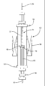
Figure 2 schematically illustrates the apparatus used for oxygen permeation
experiments;
Figure 3 is a plot of oxygen flux against time at 950 C for a selective oxygen-
permeable membrane made from a composition in accordance with the present
invention;
Figure 4 is a plot of oxygen flux against time. at 1000 C for a selective
oxygen-
permeable membrane made from a composition in accordance with the present
invention;
Figure 5 is a plot of oxygen flux against the reciprocal of temperature at
different
oxygen partial pressure differentials for a inembrane made from a composition
in
accordance with the present invention;
Figure 6 is a plot of oxygen flux against the reciprocal of temperature for
different
thicknesses of a membrane made from a composition in accordance with the
present
invention;
Figure 7 is a plot of oxygen flux against the log of the partial pressure
differential
across a membrane made from a composition in accordance with the present
invention;
Figure 8 schematically illustrates a process using a reactor with a selective
oxygen-
permeable membrane, in which oxygen is separated from air in one zone of the
reactor and
fed into a second zone of the reactor for use as a reactant in the catalytic
partial oxidation
of methane; and
Figure 9 is a plot of catalytic perfortnance and oxygen permeation performance
in the
partial oxidation of methane using a reactor with a selective oxygen-permeable
membrane
made from a composition in accordance with the present invention;
A composition in accordance with the present invention was prepared by
separately
synthesising Gd0.2Ceo,801.9 (GDC) and Gdo,2Sro,8FeO3_5 (GSF). Nitrate salts of
the metals
in respective stoichiometric quantities were dissolved in water. A quantity of
EDTA and
citric acid were each added so that the molar ratio of each of the EDTA and
citric acid to
the total quantity of metal ions was 1. The pH of the solution was then
adjusted to a value
of between 6 and 8 by addition of ammonium hydroxide solution. Water was
removed by
evaporation at about 80 C using a hot-plate. A gel formed, which was then
ignited with a
flame in order to combust residual organic material. The resulting powder was
subsequently calcined under air for 5 hours at 900 C to yield the respective
oxide product.
Membranes were prepared using the following procedures.
CA 02654364 2008-12-04
WO 2007/148057 PCT/GB2007/002252
8
Exam-ple 1
Powders of eacli of the GDC and GSF compounds were mixed together in a ratio
of
60wt% GDC to 40wt% GSF. They were then compressed into a disc at a pressure of
200MPa, and heated at 1400 C for a period between 3 and 5 hours to form the
final
composition (GDC60/GSF40), which could also be used as a selective oxygen-
permeable
membrane in subsequent experiments. The disc of GDC60/GSF40 was polished to a
thickness of 0.5mm, and a coating of a porous La0.6Sr0.4CoO3_6 (LSC) was
applied in order
to improve oxygen exchange at the membrane surface. This was achieved by
preparing a
paste of 40wt% LSC in 60wt% terpineol-saturated methyl cellulose, applying a
coating of
the paste to the membrane, and calcining the coated membrane at 900 C in air
for one
hour.
Comparative ExampZe 2
GSF-only and GDC-only membranes were fonned by compressing a disc of GSF or
GDC at 200MPa, and heating it to a temperature of 1250 C for 3 hours. The disc
was then
polished and coated with LSC in an identical way to the membrane of example l:
Experiment 1
X-ray diffraction (XRD) patterns, as shown in Figure 1, were measured for the
pure
GDC 1 and GSF 2 compounds, and also for the GDC60/GSF40 membrane 3. XRD
patterns were collected before any LSC coating was applied. A Rigaku D/Max-RB
diffractometer was used, employing Cu Ka radiation. Data were collected over a
20 range
of 20-80 in steps of 0.02 .
The data show that the membrane composition, after mixing and treatment at 25
1400 C, comprises a mixture of the two constituent phases; no new phase is
apparent. The
data also show that GSF adopts a perovskite structure, and GDC adopts a
fluorite structure.
Experiment 2
An LSC-coated disc of GDC or GSF was loaded into a vertical high-temperature
gas
permeation cell. On one side of the membrane (corresponding to the first zone
of the
vessel), a flow of a dry mixture of 80% nitrogen and 20% oxygen by volume was
.
introduced at a rate of 100mL/min (adjusted to standard temperature and
pressure (STP),
CA 02654364 2008-12-04
WO 2007/148057 PCT/GB2007/002252
9
i.e. 0 C and 1 atin pressure). A helium (or methane) sweep gas was fed to the
other side of
the membrane (corresponding to the second zone of the vessel) to assist
removal of
permeated oxygen. A schematic overview of the oxygen separation process is
illustrated in
Figure 2. The separation vessel 10 comprises two zones, a first zone 11 to
which air is fed
through inlet 12, and a second zone 13 to which a helium sweep gas is fed
through inlet 14.
The membrane 15, sealed by a silver ring 16, separates the first 11 and second
13 zones.
Oxygen permeating through the membrane from the first to the second zone is
swept out of
the separation vessel by the helium sweep gas through outlet 17. Oxygen-
deficient air that
does not permeate the memb'rane is removed from the first zone through outlet
18.
In oxygen permeation experiments, the membrane was maintained at a temperature
of 940 C using heater 19. Temperature at the membrane was measured ixsing a
thermocouple 20 located within a thermowe1121 which extended to a point just
above the
membrane 15. An oxygen partial pressure of 21 kPa was maintained in the first
zone.
For the GDC membrane, the initial oxygen flux was below detectable liinits,
i.e. less
than 0.001 mL cm Z min 1.
For the GSF membrane, the helium flow on the permeate side of the membrane was
adjusted to give an oxygen partial pressure of 5 kPa. The initial oxygen flux
across the
membrane was 0.26 mL cm 2 miri 1. ,
These experiments show that GDC, in the absence of electronic conductivity,
does
not function effectively as a selective oxygen-permeable membrane. GSF,
however,
having both electronic and oxide conductivity, can allow the selective
penneation of
oxygen.
Experiment 3
An LSC-coated disc of GDC60/GSF40 was subjected to the same procedure as
described in experiment 2, with the exception that the temperature of the
membrane (gases)
was 950 C, and the experiment was continued for a period of 1100 hours. A plot
of
oxygen flux (J 02) in units of ml cm 2 miri 1 against time is shown in Figure
3.
The results show that oxygen flux increased steadily over the first 600 hours
on
stream, the initial flux of 0.46 mL cm ? min 1 increasing to 0.63 mL cm -2
miri '.
CA 02654364 2008-12-04
WO 2007/148057 PCT/GB2007/002252
Experiment 4
The same procedure as described in Experiment 3 was used for a GDC60/GSF40
membrane, with the exception that the temperature of the membrane (gases) was
1000 C
and the period of time on stream was 350 hours. A plot of oxygen flux against
time is
5 shown in Figure 4.
The results show that oxygen flux was higher than at 950 C, which flux also
increased with time on stream. The membrane exhibited an initial flux of 0.61
mL cm a
miri 1, which increased to 0.71 mL cm 2 min-l within the first 300 hotirs on
stream.
10 Experiment 5
Oxygen flux through a GDC60/GSF40 membrane at temperatures of between 800 C
and 1010 C was studied. A flow of 100mL/min (STP) of the oxygen-nitrogen
mixture at
an oxygen partial pressure of 21 kPa on one side of the membrane was used, and
the
helium gas flow on the other (permeate) side of the membrane was adjusted to
give an
oxygen partial pressure of 0.5kPa.
Experiment 6
The procedure was the same as Experiment 5, except that the helium gas flow on
the
other (permeate) side of the membrane was adjusted to give an oxygen partial
pressure of
1.0kPa.
Experiment 7
The procedure was the same as Experiment 5 and 6, except that the helium gas
flow
on the other (permeate) side of the membrane was adjusted to give an oxygen
partial
pressure of 2.OkPa.
Results of oxygen flux versus the reciprocal of temperature at different
oxygen
partial pressure differentials for Experiments 5 to 7 are shown in Figure 5.
The results
show that oxygen flux increases with temperature, and with an increase in the
oxygen
partial pressure differential.
CA 02654364 2008-12-04
WO 2007/148057 PCT/GB2007/002252
11
Experiment 8
The same procedure as Example 6 was followed, except that a 1.0mm
GDC60/GSF40 membrane was used, at temperatures of between 825 C and 940 C. An
oxygen partial pressure on the permeate side of the membrane was maintained at
a value of
1.0kPa.
Results of oxygen flux against the 'reciprocal of temperature for membranes of
different thickness for Experiments 5 and 8 are shown in Figure 6. The results
show that
oxygen flux is higher for the thinner membrane.
Table I shows the calculated oxygen permeation activation energies for
Experiments
5 through to 8.
Table 1: Oxygen Permeation Activation Energies
Experiment Membrane J 02 (kPa) Activation
Thickness (mm) Energy (kJ/mol)
5 0.5 0.5 105.3
6 0.5 1.0 103.4
7 0.5 1.5 104.6
8 1.0 1.0 94.5
oxygen partial pressure on the permeate side of the membrane.
The higher activation energies calculated for the=0.5mm membrane indicate that
oxygen exchange at the membrane surface is more important on the oxygen flux
than in
the 1.0 mm membrane, in which the bullc of the membrane has greater influence
on oxygen
flux. This is also demonstrated by the dashed line on the plot of Figure 6,
which represents
the predicted oxygen flux of the 1.0mm meinbrane of Experiment 8 corrected or
normalised to 0.5rnm. The flux is predicted to be higher than is actually
observed (c.f.
results of Experiment 5), and the difference increases at lower temperatures,
showing the
increased iinportance of surface exchange over bulk diffusion for the thinner
membrane.
Figure 7 shows the results of oxygen flux versus the log of the partial
pressure
differential for the 0.5mm membrane at two different temperatures, 850 and 950
C. In this
CA 02654364 2008-12-04
WO 2007/148057 PCT/GB2007/002252
12
case, the partial pressure differential is expressed as the ratio between the
oxygen partial
pressure in the oxygen/nitrogen mixture (P02') and the oxygen partial pressure
in the
oxygen/helium mixture on the permeate side of the membrane (P02").
The results show that at 950 C the gradient is constant, indicating bulk
diffusion is
the main factor limiting oxygen flux. Conversely, at 850 C, the gradient is
non-linear,
being larger at lower oxygen partial pressure differentials, indicating that
surface exchange
becomes important at this lower temperature.
Experiment 9
The use of a 0.5mm GDC60/GSF40 membrane to directly separate pure oxygen from
air, for feeding to a reaction for the partial oxidation of methane to carbon
monoxide and
hydrogen was studied. The membrane was loaded into a membrane reactor, the
membrane
separating the reactor into two zones. Iilto one of the zones (the second
zone) was
introduced a LiLaNiO/-y-alumina partial oxidation catalyst, which had been
prepared by an
impregnation method in which gamma-alumina was immersed for 24 hours in a
solution
comprising lithium nitrate, nickel(II) nitrate and lanthanum(III) nitrate in a
1:1.6:2.6
Ni:Li:La mole ratio. The resulting catalyst had a nickel loading of between 5
and 10% by
weight. The catalyst was not pre-reduced before being loaded into the reactor.
A
schematic overview of the process is illustrated in Figure 8, which shows a
reactor 100
with a first zone 101 and a second zone 102 separated by a selective oxygen-
permeable
membrane 103, sealed using gold rings 104. Air is fed to the first zone 101
through inlet
105. Oxygen permeating the membrane 103 enters the second zone 102 of the
reactor. To
the second zone of the reactor is fed a hydrocarbon, for example methane 106.
The second
zone also contains a partial oxidation catalyst 107. The methane combines with
the
permeated oxygen in the presence of the catalyst 107,.and reaction occurs. An
oxygen/nitrogen mixture with reduced oxygen concentration is removed from the
first zone
101 of the reactor through outlet 108, while a stream comprising unreacted
methane and
oxygen, together with reaction products and by-products is removed from the
second zone
of the reactor through outlet 109.
Initially, a flow of 5mL/min pure methane (STP) diluted with a flow of
20mL/min
helium (STP) was introduced into the second zone of the reactor (the catalyst-
containing
zone). Air was introduced into the first reactor zone at a flow of 150mL/min
(STP). The
CA 02654364 2008-12-04
WO 2007/148057 PCT/GB2007/002252
13
membrane was held at a temperature of 950 C using heater 110, as measured
using
thermocouple 111, and total pressures of 1 atm on both sides of the membrane
were
maintained.
Results are reproduced graphically in Figure 9, which displays methane
conversion,
200 (m), CO selectivity 201 (o), H2 : CO molar ratio, 202 (+), and oxygen
flux, 203 (d).
After 30 minutes on stream, methane conversions of 30% were observed, with a
selectivity
to CO of 100% and an oxygen permeation flux of 0.85 mL cm 2 miri 1. After
about 230
hours on stream, the conversion had increased to 60%, with an oxygen flux of
2.4 mL cm l
min '. These results correspond to region 204 of the graph in Figure 9. The
helium flow to
the second (catalyst-containing) reactor zone was then switched off, which
resulted in an
increase in methane conversions to 99%, and an increase in oxygen flux to 3.3
mL cm 2
miri 1. These results correspond to region 205 of the graph in Figure 9. After
380 hours on
stream, the CH4 flow rate was increased to l OmL/min (STP). This resulted in
an increased
oxygen flux of 5.2 mL cm ~ miri 1, while conversion remained at 99%. These
results
correspond to region 206 of the graph in Figure 9. Selectivity to CO
throughout the
experiment was 100%, and the H2 : CO mole ratio was consistently 2.: 1, with
only minor
variations being experienced. '
The results show that partial oxidation using an oxygen-membrane reactor with
a
membrane made of a composition in accordance with the present invention can
produce
high methane conversions with high carbon monoxide selectivity over several
hours on-
stream, even when one side of the membrane is in contact with a hydrogen-
containing
reducing atmosphere at high temperatures and pressures.