Note: Descriptions are shown in the official language in which they were submitted.
CA 02654451 2008-12-04
WO 2007/149261 PCT/US2007/013711
-1-
IMPROVED TRACKING SYSTEM
Background of the Invention
Businesses provide garments and other supplies to their workers for a number
of reasons.
Such garments may include uniforms that are utilized to identify the worker as
an employee of
the company. Restaurant workers, delivery personnel and auto mechanics are a
few examples of
the types of employees who may be seen in uniform. The use of uniforms for
employees may
also contribute to the brand image of the employer by helping to present a
consistent impression
to the public through its employees.
Specific types of garments may also be provided in specialized circumstances.
In food
preparation and processing settings, an employer may provide specific
guidelines for use and
also for cleansing or laundering of a garment. In some cases, regulations and
laws may set
certain minimum guidelines as well. Clean room settings (such as for
production of
microelectronics) also require specialized garments in order to prevent
contaminants from being
introduced into the clean room setting.
The uniforms and other garments are often obtained by businesses as part of a
program
from a garment provider which in turn may also provide laundering and
optionally sanitizing and
other services. In such an arrangement, the business customer may specify to
the garment
provider the number and type of garments, pick up dates, turn around times and
other parameters
for service. The garment provider then delivers the garments to the customer
for use by
employees, picks up the soiled garments, processes the garments (e.g. launders
them) and then
returns the garments to the customer's location. Garment providers may provide
for laundering
and processing of items in addition to clothing and uniforms, including shop
towels (such as
used in a car repair facility) and floor mats (such as found in entryways and
hallways) as well as
other items that require laundering or processing. It should be understood
that the use of the
terrn "garment" as used is therefore non-limiting and therefore may, in proper
context, be
understood to include clothing such as uniform as well as towel, mats and
other items that can be
laundered or otherwise processed in the garment provider's facilities for the
customer.
Costs in such a program are based on a number of factors including, but not
limited to,
the number of garments in the program, the service volume for such garments,
the level of
service for garments, charges for enhanced or proprietary treatment of
serviced garments,
charges for lost or damaged garments, and charges for new wearers .entering
the program. The
customer wants to receive invoices that are accurate and fair and to know that
what is billed has
been performed to their expectations and that the service has good competitive
value.
CA 02654451 2008-12-04
WO 2007/149261 PCT/US2007/013711
-2-
Obviously, customers want to have control over how much is spent on such a
program.
Customers prefer billing without spikes and dislike non-productive charges
i.e. loss or damage.
They are also receptive towards measures to reduce non-productive cost events.
One classic dispute between a garment provider and a customer arises when a
garment or
other item is reported missing, whether the absence is discovered by the
customer or reported to
the customer by the garment provider. The dispute is whether the item has been
lost within the
customer's organization or during servicing by the garment provider. Service
contracts usually
allocate the replacement cost of the garment to whoever lost the garment.
Another dispute arises
when a garment is damaged and whether the damage arose from use in the
customer's facility or
to during processing within the hands of the garment provider. These disputes
can best be resolved
when there is information on the location of the ganrnent and its condition
that is available to
both sides allowing them to reach an agreement on the facts. However, the
facts are often
unavailable or obscured by a lack of records on what has been delivered, what
was turned in at
the customer's site, how it is used, and the condition of the garment.
The customer wants the garment provider to be responsive when exceptions or
disputes
arise. This means that they want agreement on the facts of the exception (e.g.
damage or loss),
agreement on actions with short time to correct, and visibility into the
correction process i.e.
tracking garments in the system. A system that would allow the customer to be
able to trust the
garment provider and its performance would reduce the time needed to
administer the program.
Generally, industrial laundry garments are handled in random bundles when they
are
soiled (used and to be returned to the industrial laundry plant for cleaning).
These bundles are
most often managed in bulk since dealing with the garments on an individual
basis is very labor
intensive. After arriving at the plant the laundry is typically separated in
types dependent of
what should be washed together. Some separation of different delivery routes
and accounts may
occur too from sequential unloading of the route trucks, and by design, to
separate route lots in
the laundry process. Garments are normally manually separated, arranged on
hangers, and hung
onto a rack or conveyor system after completing the drying process.
Complete manual identification of each garment at the soil entry is nonmally
cost
prohibitive. Therefore, garment provider processes currently include
identifiers on garments for
manual and automatic tracking. These identifiers include human readable text
and barcode
information. The information on these labels is used by garment providers for
automatic
processing and for manual reading where automation has not been implemented.
It is also
understood that HF RFID tags have been tested in some industrial laundry
plants.
CA 02654451 2008-12-04
WO 2007/149261 PCT/US2007/013711
-3-
However, these approaches result in unacceptable labor costs. For barcode
implementations, readers require line of sight betweein reader and the
identifier. For HF RFID
tags, tend to require special machines to be used to separate garments in
front of the reader due
to their limited capability to quickly read many tags in front of the reader
at the same time. It
also may require manual labor to feed the separation machine.
A system that would give a garment provider the ability to automatically scan
and track
garments without line of sight to the label and even the ability to identify
individual garments
within bundles of clean or soiled garments would allow ganment providers to
achieve greater
processing efficiencies and implement reporting and tracking protocols to
provide customers
with important data regarding garments in their program with a higher level of
confidence in the
data than can currently be achieved.
Summary of the Invention
It is an object of the invention to provide a system that allows for
conducting inventory
and maintaining records of inventory for new garments in a garment provider's
facility as well as
verification procedures for ensuring the integrity of information on such
systems.
It is an object of the invention to provide a system that allows for rapid
assembly of
elements of customer orders, for ensuring accuracy of filled order and for
measuring the timing
of one or more steps in the order assembly process.
It is an object of the invention to provide a system that allows an RFID tag
in a garment
to be identified to a particular user as a single piece or, optionally, as
part of a larger set of
garments.
It is an object of the invention to provide a system that allows a customer to
use the
information in the RFID tag in the garment to monitor and, optionally, control
the movement of
the wearer, of the garment. It is a further object of the invention to use
such a system in a food
processing facility to enforce HAACP and other protocols to increase food
safety. It is a further
object of the invention to use such a system in a clean room facility to
reduce introduction of
potential contaminants into the clean room system. It is a further object of
the invention to use
such a system to use such a system to record multiple garment locations and
multiple events and
to use this data to develop verifying documents in support of compliance
requirements as
promulgated by government or other organizations.
It is a further object of the invention to allow a customer of the garment
provider to use
the information in the RFID tag in the garment to control access of the
customer's employee's to
CA 02654451 2008-12-04
WO 2007/149261 PCT/US2007/013711
-4-
one or more areas of a customer's facility.
It is a further object of the invention to use the information in the RFIDtag
in the
garment to identify the garment when it is checked back in to a central
collection (e.g. for
laundering).
It is an object of the invention to provide a system that allows for highly
accurate
tracking of garments being delivered from a customer's possession back into
the possession of
the garment provider.
It is an object of the invention to provide a system that allows a garment
provider to
provide a customer a highly accurate series of reports regarding one or more
of the following:
total number garments in customer's program, location of the garments in the
customer's
program, status of the garment and rate of loss. The information can be used
to minimize
inventory, maximize garment useful life through FIFO management, manage
planned wash
cycles for garment obsolescence, and to use the data for establishing root
causes to garment
damage by matching the damaged garment, through the tag's identifier to the
wearer, and further
to the source of the damage in that wearer's behavior or environment.
It is an object of the invention to provide a system that allows the recording
of events and
locations for garments through the garment's life for verifying that garments
issued are
accounted for.
It is an object of the invention to provide a system that allows a data
processing unit to
zo compare the identification read from one garment with a master set of
garment identifiers
comprising all garments authorized to be in service, and to produce an alarm
signaling that the
one garment read is unauthorized, in the case the read identifier does not
match any identifier in
the master set, thereby preventing the use of an unauthorized garment.
It is an object of the invention to provide a system that allows using a
reader to locate one
or more garments by traversing a large set of garments with the reader and
determining the
location of the garment by a garment read event. When the garment read event
occurs it
becomes known that the garment is located within the reader's read range
location at that time.
It is an object of the invention to provide a system to develop a garment
location map in a
garment storage and/or processing facility (including storage within a
processing facility). By
attaching RFID tags to predetermined fixed locations within the garment
storage facility these
locations can be used to establish the location of a reader traversing the
whole or part of the
garment storage facility. When the reader is traversing the ganment storage
facility it will read
garment tags and location specific tags sequentially as the reader traverses
the facility and tags
CA 02654451 2008-12-04
WO 2007/149261 PCT/US2007/013711
-5-
enter the reader's read range. The resulting sequence of garment and location
specific identifiers
thus developed can be used to establish the location of each garment read
described as between
two or several location specific tag identifiers. '
It is an object of this invention to provide a system that can be used for
processing of data
for garments that have been sold directly to the customer and that are
laundered and maintained
by the customer or a third party.
It is an object of this invention to provide a system that automates the RFID
tagging of
large numbers of garments for enabling existing garments to become usable
within the invention
RFID based system in general. .
It is an object of this invention to provide a system that can be used for
reading and
validating the location of garments and other items on a truck.
It is an object of this invention to provide a system that includes the
capability to
selectively, as intended by the operator or as determined by the system,
either read many tags
from a longer distance (i.e. 10 ft) or to read a smaller number of tags
(including single tags) at a
smaller distance, discriminating this smaller number set of tags from the
large number set of tags
also when the larger set is in the vicinity (outside 1 ft, within 20 ft) of
the smaller number of
tags. This capability can be used for uniquely identifying garments in a
number of settings
including garments located close together, garments moving at high speed
through a plant, and
garments moving through an automatic sorting process system such as found in
an industrial
laundry or dry cleaning setting.
It is an object of this invention to provide a tag system that includes a tag
encapsulation
that is suitable to withstand the rigors of handling, use, washing, drying and
other processing
within the industrial laundry process, home washing, and dry cleaning.
Brief Description of the Drawings
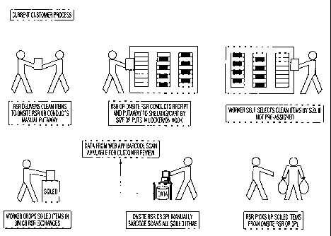
FIG. I shows a flow chart with steps in a typical customer garment process.
FIG. 2 shows a flow chart of the process of FIG. I with a system of the
present invention
implemented.
FIG. 3 shows a flow chart with steps in a typical customer process for clean
room
garments.
FIG. 4 shows a flow chart of the process of FIG. 3 with a system of the
present invention
implemented
CA 02654451 2008-12-04
WO 2007/149261 PCT/US2007/013711
-6-
Detailed Description of the Invention
The system described herein utilizes RFID tags and tag readers capable of
reading
information on the tags as well as writing information to the tag. The system
also includes data
processing capability that allows for highly accurate tracking by a garment
provider of garments
and other items through the use and processing cycle of such items. The
garment provider may
also provide varying levels of this tracking information to its customers
depending, for example,
on the customer's desire for such information and in part on the customer's
ability to utilize and
store such information. Garments may be tracked beginning at the arrival of
the garments in the
garment provider's facility, through delivery to the customer, upon pick-up
from the customer
site and upon arrival of the garments back at the garment provider site.
Additionally, garments
may be tracked during the process of initial order fulfillment, upon loading
of an order or parts
of an order onto a vehicle for delivery, at the time the vehicle leaves the
garment provider's
facility, at the time of arrival at a customer's facility, upon unloading of
the order or part of the
order at the customer's facility, and upon delivery of the garments within the
customer's facility
by the garment provider or by an employee of the customer. Information could
also be collected
by the ganment provider or the customer regarding the status of garments or
other items while
residing at the customer's facility for use in monitoring or other activities
such as identification
of non-personalized garments to a wearer, tracking the position of the garment
or other item
through the customer's facility, utilization of information-on the RFID tag of
one or more
garments assigned to an employee to monitor or control access to various
locations in the
customer's facility and to monitor turn-in compliance by employees for
garments issued to them.
RFID Tags
RFID tags may be GEN 1(LJHF) tags in certain applications, however UHF RFID
tags
operating at 860-960 MHz (within a subset of this range mandated by applicable
national laws or
regulations) and utilizing GEN2 or later version specifications may be used to
allow for faster
reading of tags, to allow for storage of more information relating to the
identity of the garment or
other item, the status of the item and users of the item, and more importantly
to allow for greater
range of reading.
RFID tags useful in the invention will typically comprise an RFID chip
(typically 1-2
mm in size), an antenna, a chip saddle or other connection between the chip
and the antenna, and
a substrate into which the chip, saddle, and antenna are fixed. This assembly
is called an inlay.
The antenna may be constructed from numerous different materials, including
but not limited to
etched metal, conductive ink, conductive rubber or wire. The RFID tags
utilized in the system
CA 02654451 2008-12-04
WO 2007/149261 PCT/US2007/013711
-7-
need not contain any intemal power source, but derive power needed to activate
the memory and
transmission functions from the signal sent by a reader (i.e. passive tags)
and received by the
antenna connected to the RFID chip.
R.FID tags utilized in the system must be able to withstand the harsh
processing
conditions encountered in an industrial laundering process as well as other
conditions found in a
customer facility. Typically, RFID tags by themselves are unable to withstand
the harsh
conditions of a laundering process. Thus, the inlay may be contained within a
protective layer to
create an RFID tag. The protective layer will stand up to the conditions under
which a garment
is utilized and laundered and may have features (such as holes or structures)
that allow for secure
placement of the tag on a garment. The protective layer may be a polymer
coating, such as a
polyester, into which the inlay of the RFID tag is laminated. It should be
noted, however, that
some lamination methods or materials may not provide a protective coating that
is suitable for
garments that are laundered on an industrial basis. Laminations may fail after
repeated stress
placed on the tag during a laundering process, thus allbwing water and other
chemicals (e.g.
detergents) access to the RFID inlay.
Therefore, the protective layer may also be provided by encapsulating the RFID
inlay
using an injection molding procedure or a die casting procedure. Polymeric
materials that may
be useful in these procedures include thermoplastic elastomers such as a
SANTOPRENE
elastomer (Advanced Elastomer Systems; Akron, OH) or ELASTOCENE. Flexible RFID
tags
may also be subjected to multiple bending events during processing and/or use,
especially during
a cycle of industrial laundering. Thus, the connections between the antenna
and the chip
containing the electronics of the RFID tag should be constructed in a manner
that accommodates
this bending. For example, the area of connection between the antenna and the
chip may be
strengthened or stabilized. There may be a stronger rnaterial used in
preparation of the inlay in
the region between the chip and the antenna. Additionally, there may be one or
more
strengthening members (such as a rib) added to the inlay in the region of the
saddle (junction
between the chip and the antenna). As well, additional material(s) may be
added during
encapsulation in the region of the saddle. The material may be a viscous resin
added in a
metered amount onto exterior of the tag after encapsulation in the saddle
region. The material
would be relatively inflexible in the region of the saddle. This added resin
may also be cured to
allow it to be increasingly more flexible at distances away from the saddle.
The result is a
flattened drop that is thick enough to appear rigid in the chip/saddle area
and that is gradually
thinner and more flexible further from the chip/saddle area thereby adapting
the rigidity from full
CA 02654451 2008-12-04
WO 2007/149261 PCT/US2007/013711
-8-
chip-saddle protection to full antenna flexibility as it becomes thinner
further from the center of
the drop.
In order to minimize fracture of antenna components in an encapsulated RFID
tag,
conductive ink may be combined with electrically conductive fiber in a way
that allows the fiber
to continue to provide a conductive "bridge" in the event of fracture of
conductive ink. Another
possible solution is to replace the antenna materials previously used with
conductive rubber
material i.e. such that is used in external cell phone antennas. This
conductive rubber may be
stamped or cutout and then assembled onto an inlay. In one embodiment, the
RFID chip has
external connections that may be pressed against the conductive rubber, thus
assuring a
"flexible" connection. This is one example of a connection between the antenna
and the chip
that may be constructed in a way that allows for flexibility without
substantial loss of
conductivity between the chip and the antenna even after bending numerous
times. Some
damping of the RF signal may be experienced due to the fact that the
conductive rubber has
higher impedance than metal but this damping may be mitigated by the
possibility to use a larger
antenna due at least in part to the flexibility of this material.
In another embodiment, the encapsulation may be made of conductive rubberized
material and thereby act directly as antenna. Normally, it is desirable to
have an antenna that is
made up of two separate parts thereby creating a dipole. It can be envisioned
that two
conductive encapsulation parts are separated in the region of the RFID chip by
a portion of
encapsulation that is non-conductive. One benefit with this approach is to
achieve one
continuous material with respect to stress related parameters but to create a
discontinuity in
electric conduction thereby providing the desired dipole structure.
The tag may be situated on a garment or other item in a way that is innocuous
to the user
and at a minimum should not interfere with the user's ability to perform the
tasks assigned to
them. The tag can have a form and character that prevents it from causing
discomfort to the
garment wearer or user. Optionally, the RFID tag will have additional
identifying information
for the tag itself located on an outside surface such as in the form of a
visually identifiable serial
number or a barcode. Optionally, the tag can have the capability to be read
together with many
other tags at a large distance (i.e. 20 ft), also called far field, or to be
read as a single item and
separate from other tags located close by (i.e. 1 ft), also called near field
reading.
Size and flexibility requirements for the RFID tag are driven by the need to
make the tag
comfortable and unobtrusive for the wearer of the tagged garment. These
requirements are in a
trade-off relationship with other requirements for read range, read speed, and
industrial laundry
CA 02654451 2008-12-04
WO 2007/149261 PCT/US2007/013711
-9-
process survival. Read range and speed are improved with a bigger tag since it
is possible to get
a better RF coupling with a larger antenna. Generally, optimized tags with no
strict size
restriction are about 4 x 1 inches with the antennas folded back to fit within
the 4 x 1 inch
envelope. The unfolded dipole antenna is in this case about 7-9 inches.
However, the desired
size for an encapsulated RFID tag useful in the invention and having an
antenna capable of
supporting a practical read range is about 2x 1 inches.
Other configurations of RFID tags may also be used. For example, the antenna
for the
tag may be in the form of a conductive thread such as an encapsulated
conductive thread. The
thread can be of a flexible material that optionally has elastic and/or
expansion properties similar
to the encapsulation thereby minimizing stresses in the bond between thread
and encapsulation.
The antenna should ideally be of a length close to one-fourth of the UHF
wavelength utilized by
the RFID chip to get best RF coupling. A thread antenna can be unobtrusively
hidden inside a
folded seam, waistband, or collar. This way of integrating the antenna into a
garment or other
item allows the use of an antenna having a length (e.g. 6-12 inches) greater
than that in an
encapsulated tag. The connection between the chip and the antenna must be
rugged enough to
withstand at least some level of tension as would be placed on the antenna
components during
wear and or use.
In construction of an RFID tag using conductive thread, it may be useful to
use an RFID
chip capsule to house the RFID chip and to surround and protect the connection
between the
RFID chip and the antenna. Examples of connections that may be sheltered
include adhesive
connections and crimping of a metal or other flexible tab on the RFID chip or
the saddle around
the antenna material.
Another construction that may be useful in preparation of an RFID tag is to
construct a
thin, flexible rod having two segments capable of acting as an antenna for the
RFID tag
separated by a non-conductive element. The non-conductive element would be
sized to be
slightly less than the width of the RFID chip. A slot is defined by the non-
conductive element
that provides for access between the conductive elements. An RFID chip with
elements that can
interact with the conductive elements and provide an electrical connection
therebetween may
then be inserted into the slot allowing electrical communication between the
RFID chip and both
conductive elements. The slot may then be filled in with additional non-
conductive material.
Additionally, the construction may be encapsulated (e.g. dipped) in an
additional resin or other
coating to further protect the RFID chip.
Yet another construction may employ conductive elements connected (e.g. fused)
to side
CA 02654451 2008-12-04
WO 2007/149261 PCT/US2007/013711
-10-
of an RFID tag. In this construction, the RFID chip would have electrical
connections on each of
the top and bottom of the chip. These connections would in turn be connected
to the conductive
elements as a result of the connection to the RFID chip. This construction may
then be
encapsulated to protect the RFID chip.
It should also be noted that the connection between the RFID chip and the
antenna
components may not need to be a direct electrical connection. Rather, the
communication
between the RFID chip and the antenna components may be inductive or
capacitve. Use of such
"non-contact" communications allows for construction of more rugged flexible
tags because the
potentially sensitive direct electrical connections are eliminated.
lo RFID tags may be placed on garments or other items already in use within a
garment
provider's or a customer's system. Thus, customers who retain the garment
provider to service
their existing inventory of garments and other items may obtain the benefits
of this system as
well. The system for placement of the RFID tags on existing inventories of
garments must be
rapid and reliable in order to minimize expense of conversion to the system of
the present
invention.
RFID tags that are not adapted to withstand the processing conducted by the
garment
provider may nevertheless be used in the supply chain' prior to delivery to a
customer or even up
to the point that the garment enters into a service cycle. Garments
manufactured for the garment
provider may be tagged with a temporary (e.g. disposable or non-rugged) RFID
tag for tracking
of the garment from the manufacturer to the delivery of the garment to the
garment provider and
potentially up to the point of delivery to the customer. The temporary tag may
be written with
information regarding the source of a garment, with the type of garment, with
the identity of the
customer(s) for whom the garment is intended, and other information that may
not be as relevant
during the useful life of the garment. The temporary tag may be affixed in a
manner that allows
it to be separated easily from the garment and without damage to garment. It
may be beneficial
to have the temporary RFID tags operating at a different frequency than the
rugged tags.
Temporary tags (having RFID capability, barcode or other information) may be
used in
the supply chain from the manufacturer to the garment provider. The garment
provider may use
the temporary tags for inventory purposes and for tracking of garments and
other items received
at a main receiving facility and during distribution to regional and local
facilities that are in
proximity to a customer. For example, the garment provider may use the
temporary tag
inforrnation for directing the delivery of portions of a bulk order to a
regional or locality based
on the identity of the customer for whom the garment is intended. The
temporary tags may also
CA 02654451 2008-12-04
WO 2007/149261 PCT/US2007/013711
-11-
remain affixed to the garment up to the point of delivery to a customer in a
situation where the
garment provider is providing a direct sale of the garments to the customer.
The tags may be
used in this context, for example, to verify delivery of complete orders of
garments and/or other
items.
Order Fulfillment
A system for delivery of non-personalized garments and other items would
typically
begin with reception of an initial order from a customer. The order could
include various
portions of a uniform or of complete sets of garments to be used together by
an employee. The
garments may be those that are worn over a worker's own clothing or that are
donned at the
io customer's facility in place of a worker's own clothing.
The garment provider assembles the various parts of the order for delivery to
the
customer either from new products obtained from a third party supplier or from
existing
inventory of new products. In addition, in some circumstances, customers may
be given the
option to fill orders from the garment provider's inventory of previously used
products.
Previously used products are often supplied at a discount relative to new
products.
Some or all of the individual ganments may be tagged with an RFID tag as
described
hereinabove. Tagged garments may be individually scanned to ensure fulfillment
of the order
and optionally to associate the particular garment as a part of a particular
order. In one
embodiment, as a garment is brought into a staging area the garment may be
passively scanned
by a reader at or near the entrance to the staging area.
Garments or other items that are not individually tagged (e.g. shop towels or
small, low
value garments) may be aggregated together such as in a bag, box, tote, or
other container that is
tagged in order to ensure fulfillment of the order. Where individually tagged
garments are
placed in larger containers for delivery, the individual tags may be
associated with an RFID tag
on the container at the time they are placed in the larger container.
Garments that are personalized to the user (i.e. the customer's employee) may
be
collected as a set and various physically identifying markers (e.g. patches,
ribbons, labels) may
be applied to the garment. The RFID tags that are part'ofthe collection
specific to a user may
also be programmed to identifying the garment as "belonging" to the user.
Responsibility for the
garment, including condition of the garment and presentation for regular
cycling of the ganment
for processing at the garment provider's facility can be enforced and
compliance with customer
policies tracked by the garment provider, the customer or both.
The order may be assembled and loaded onto a vehicle for delivery to the
customer in
CA 02654451 2008-12-04
WO 2007/149261 PCT/US2007/013711
-12-
parts. As each part is loaded it may be scanned using a mobile or static
reader to obtain
information from RFID tags present in that part of the order. The various
information may be
assembled in the mobile reader or a central information point and compared to
the order to report
back on parts of the order that are still required or that the order has been
completed. Once an
s order is assembled in the garment provider facility or in the delivery
vehicle it may be scanned
and the information compared to the customer order to ensure that the order is
complete. At an
appropriate time, this information may in turn be conveyed to the customer to
ensure that the
assembled order and the customer's expectations for the order are in
agreement.
Receipt at Customer's Facility
t0 Garments are off loaded from the delivery vehicle into the customer's
facility. Multiple
readings may be utilized during the off loading process including a scan of
the delivery vehicle
prior to and after off-loading to verify the presence of the order and the
removal from the
delivery vehicle. The garment provider delivery personnel may also scan off-
loaded garments to
verify delivery and also to receive further delivery information directing the
garments to the
15 various receiving areas designated by the customer. For example, in a food
processing facility,
certain garments may be designated for receipt and use in raw food processing
areas and certain
garments may be designated for receipt and use in finished food or packaging
areas.
Additionally, orders to a customer facility may be further broken down for
delivery of garments
to particular employees. For example, garments assigned to a particular
employee may be
20 delivered to a locker assigned to that employee. ,
The system has the capability to allow the custOmer to view and if desired to
print a
receipt or other report at the customer's site including all items scanned by
the system during the
time the time removed from the vehicle and delivered during a route site visit
by an RSR. The
system may also have the capability to capture the customer's signature or
other mark indicating
25 acknowledging that a report has been received and/or reviewed by the
customer.
The system has the capability to scan only one set of garments while being
worn by a
wearer and successfully identify all garments on the wearer. The system may
also be configured
to receive identifier information from an external system that identifies the
wearer of the
garment. Thus, at a site where garments are issued to a wearer for multiple
uses (e.g. a
30 personalized or a tailored uniform) the system can ensure that all garments
being scanned are
properly wom by the wearer. The system may also be configured with the
capability to associate
the wearer's identity with the collection of the garments on the wearer at the
time of
identification. This marrying of garments to the wearer may be performed with
no or minimal
CA 02654451 2008-12-04
WO 2007/149261 PCT/US2007/013711
-13-
extra labor. For example, the system may utilize a station where only one
wearer at a time is
scanned and in which the user provides a personal identification at a
previously installed
identification position (i.e. at an access control point or even the point of
egress from a donning
area within the customer's facility). The identity information provided by the
wearer at the
identification point may then be linked or associated with the information
obtained from the tags
present on the garments worn at the time of identification. Such information
transfer could be
initiated by keyboard input by the wearer or input from a security
identification device into the
system.
Often a customer site will utilize mats at building entrances or areas that
may present slip
and fall hazards. Mats are often carpeted on one side and rubberized or
otherwise non-slip on
the other side. Garment providers often provide mats on a rental basis and
periodically replace
the mats, retuining the soiled mats to the facility for cleaning. Mats may be
provided in standard
configurations and colors by the garment provider. Mats may also be custom
manufactured to
meet the specific requirements of a customer. The cost of the mats,
particularly custom mats, is
substantial and keeping track of the location A system of RFID tags may be
used to monitor the
placement of mats within a customer's location and the location of mats within
the garment
provider's delivery and.
An RFID tag may be fixed to an agreed mat placement location permanently or
semi-
permanently (e.g. with adhesive, tape, or similar method). When a service
representative places
a mat in the agreed placement location, a scanner may be used to scan both the
RFID tag inside
the mat and the RFID tag signifying the agreed placement location. The scanner
records
identifying information from the two tags to associate the specific mat with
the specific agreed
placement location. Optionally, the scanner may log the time and date of the
placement, the
identity of the service representative and other data. An entry in the
placement service record
for the customer or the customer's site may then be created from this data.
This placement
service record can be made basis for transfer of custody of the mat from the
service
representative to the customer. After an agreed upon time, the service
representative can scan
each mat that is removed from the agreed placement locations for processing,
thereby signifying
return of custody to the mat rental company. This type of custody tracking
greatly minimizes
disputes over custody of any lost mats.
RFID can similarly be used within the customer's environment to record service
items by
scanning local RFID tags placed within or close by each service item. Such
service items may
CA 02654451 2008-12-04
WO 2007/149261 PCT/US2007/013711
-14-
be mats, soap, shop towels, bathroom tissue and more. RFID can be used in the
field to validate
personnel service activities (using a principle similar'to that of a night
watch man's key). This
capability can be used for quality of service tracking and for charges for
incremental services
Use of the System While an Employee is at Work
In situations where employees provide services to businesses or to the general
public and
where a uniform provided by the employer confirms that the wearer represents
the employer, the
employer may desire to obtain increased opportunity to track, secure and
validate uniform
garments to prevent a third party from impersonating a legitimate wearer by
donning a lost or
stolen garment. Employers may find such increased opportunities particularly
important in the
case of professional uniforms, since the uniform itself implies that the
wearer possesses a certain
position or authority. Unfortunately, the implication of position or authority
from a garment (for
example, a security services or a law enforcement uniform) might be used
surreptitiously by a
person or persons in the process of committing a criminal or fraudulent act.
Analogous
relationships exist within medical care and elder care as well as in many
other private,
commercial, and public environments.
The system of the invention can be used to provide control over such uniforms
and to
provide for notifications or alanns where garments are not accounted for
within certain
parameters. For example, garments may be selected by the employer for delivery
to the
employer's facility. The garments may be pre-identified to the employee, such
as at the gannent
provider's facility. The employer may provide order information as well as
certain employee
specific information that will allow tracking of the garment between the
garment provider, the
employer and the employee once the information is associated with or embedded
into the RFID
tag. As the garments are delivered, the employer's representative may confirm
receipt and direct
the placement of the garments in the employer's facility. The garments may be
delivered
directly to an employee-specific location (such as a locker) or the garment
may be issued directly
to the employee. This delivery may be confirmed by use of one or more readers.
In one
altemative, an employee may be required to present additional identification
to show that the
garments worn by the employee match to a separately issued identification card
or to another
identification (such as an employee-specific password) in order to proceed out
of the employer's
facility.
In certain service provider situations, it is envisioned that the system may
provide for
communication between low cost readers in residences and businesses connected
through a
communication system to a remotely located identity data services system in
order to validate
CA 02654451 2008-12-04
WO 2007/149261 PCT/US2007/013711
-15-
that a contractor or visitor has properly authorized credentials. The system
would operate by
reading one or more RFID tags in a uniform and confirming the tag identity
with the data
services system. The data services system could in turn communicate with the
employer's
network system in order to confirm that a specific employee or contractor was
directed toward a
particular location.
The system may also be used to track and even control movement of a wearer
within the
customer facility. For example, a particular wearer may be denied access to
certain areas of a
facility (e.g. because the wearer lacks the training to be in a certain area
or the area contains
sensitive, trade secret information for which the customer desires to restrict
access). Also, the
lo wearer may be qualified to enter certain areas, but could take one or more
actions that would
disqualify the worker from entry into the area, at least with the garments
being worn by the
wearer at that time.
For example; in a food processing facility, company practices and policies may
dictate
that workers in the raw food processing areas be denied access to finished
food or packaging
areas. This restriction may even apply to such workers where they have not yet
entered the raw
food processing area. Moreover, a worker normally assigned to the finished
food or packaging
area may enter the raw food processing area, but may not then reenter the
finished food or
packaging area. Such restrictions may also be specified in the HAACP plan for
a given facility.
The system of the invention may keep track of such a worker's movements within
the
facility and deny entry into one or more areas within the facility by
physically locking out the
wearer from the proscribed area, by sounding an alarm at the entrance to the
proscribed area
and/or reporting the attempted entry into the proscribed area to the proper
level of management
within the customer organization to address the matter:
Similarly, in clean room settings, a wearer may don a set of clean room
garments and
marry up his/her personal identification information to one or more of the
RFID tags associated
with the garments. When the wearer attempts to enter the clean room facility,
the system may
check to ensure the wearer is in possession of all the required garments. The
system may also
check to ensure that the wearer is properly granted entry into the clean room
envirorunent based
on the wearer's job description and level of training. The system may also
check to ensure that
one or more of the garments have not left the staging area for entry into the
clean room, thereby
disqualifying an otherwise qualified wearer from entering into the clean room.
Similarly, a garment may be married up to a location by reading the garment
RFID tag
and a dedicated tag identifying the location. Examples are locations such as
lockers, hangers,
CA 02654451 2008-12-04
WO 2007/149261 PCT/US2007/013711
-16-
rails, shelves, totes, carts and other locations. This marrying up of a
garment with a location may
be used to validate actions, such as the fact that services have been
performed. Examples may be
that a garment has been delivered to the right location, accessed by the
wearer, or that a
dispenser such as a shop towel or soap dispenser has been serviced (i.e.
filled).
The system can include capabilities that allow the system to read garments at
a location
and a time and to measure the duration or frequency of use of the garment.
This information can
be used for certification of garment parameters specified for use in a
particular process.
Examples may include the number of times a clean room garment can be donned
without return
to the garment provider for processing, the number of work shifts or work
hours a food
processing garment can be used before return to the garment provider for
processing. The
system can also be configured to provide reminders to an employee regarding
return of garments
for processing. For example, unifonns used by employees in provision of
service directly to
customers may be placed on a regular schedule for processing. If an employee
has not returned
the garment for processing according to the schedule for the garment, the
system at a customer's
facility may generate notices (such as electronic mail messages) to the
employee or to the
employee's supervisor. The system may also deter or prevent the employee from
accessing
certain areas in the customer's facility if an employee is wearing a garment
that should not be in
use.
Return of Garments to Garment Provider Facility
Garments may be returned to the garment provider in a number of ways. The
garments
may be placed in a common receptacle with garments from other employees of the
customer. In
the present system, the receptacle may have a reader to interrogate the RFID
tag associated with
the garment to obtain information regarding the owner. Once the employee has
finished with the
garment, the garment is placed in the receptacle and the reader interrogates
the tag. Information,
such as the identity of the employee, the date the garment is due for
servicing and whether the
garment was associated with other garments (e.g. sport coat and slacks; clean
room uniform)
may be collected and reported to the customer's information systems. In
certain cases, a receipt
may be issued to the employee, especially in the case of higher value
garments. Information
may also be obtained in regard to garments in a receptacle by use of a
handheld RFID reader. In
such a system, the customer may desire to scan the contents of the receptacle
prior to pick-up by
the garment provider.
The customer can use the inforrnation to track usage by employees such as in a
situation
where an employee is using multiple garments in a single day. The customer can
also use the
CA 02654451 2008-12-04
WO 2007/149261 PCT/US2007/013711
-17-
information to verify the garments collected by the garment provider for
processing. For
example, the garment provider may independently cdllect information from the
RFID tags on the
garments upon collection from the customer who can in turn compare the report
from the
garment provider to the results by the customer. In the case of a discrepancy,
a garment provider
may collect information on the collected garments again to ensure that all
tags are read or could
manually inspect the contents of the collected garments to determine whether
the garment is
physically present.
Processing at Garment Provider Facility
Garments are returned to the garment provider facility, typically in a vehicle
owned or
controlled (e.g. leased) to the garment provider and driven by a garment
provider employee or
contractor. Once the vehicle arrives at the garment provider facility,
ganments are off-loaded
into a receiving area. The contents of the vehicle may be scanned prior to off-
loading to set a
baseline for processing of the garments. Garments may also be scanned as they
are removed
from the vehicle. Typically, such scanning would be done on a collection (e.g.
a bag) of
garments prior to routing within the facility. Some or all of the results of
the scanning may also
be reported back to the customer in addition to the report generated at pick-
up or in place of such
a report.
Information from the scanned loads of incoming soiled garments have that have
arrived
at the plant and been sorted and individually scanned can be assembled into a
data set that
completely describes the number of garments by type, by process, and by labor
required to
process. This information can then be used to allocate labor for processing in
each sequential
step in the laundering and further processing thereby maximizing labor
efficiencies and avoid
periods of inactivity for on-site labor resources. The laundry parameters for
the soiled garments
in the plant can also be used for planning and scheduling to ensure
availability of chemicals
(detergent, fabric softener, anti-microbial) and other supplies. Information
obtained from
scanning of incoming garments may also be used in other aspects of plant
planning including
processing sequence and allocation of water, temperature, equipment depending
on the required
mechanical action for processing
In one example the items received at the facility may include the following
categories of
products that would need to be routed within the facility:
1. Returned soiled garments
2. Returned clean garments
3. Damaged garments
CA 02654451 2008-12-04
WO 2007/149261 PCT/US2007/013711
-18-
4. Destroyed garments
5. Soiled samples
6. Clean samples
7. Soiled repair
8. Clean repair
9. Soiled return mats
10. Clean return mats
11. Soiled return shop towels
12. Clean return shop towels
Each of the items in a return load can be categorized and directed accordingly
within the
facility. Optionally, the status of the item may be stored in the RFID tag for
the item. Damaged
items can be evaluated for continued use in the customer's program or may be
decommissioned
from the program. Repair items may be attended to during the processing at the
facility and
evaluated for further use in the customer's program. The status of a damaged
or a repair item
may be entered into the system and this status information may be entered into
the memory of
the RFID tag as well. Costs for damaged items, for repairs to repair items,
for destroyed items
and for decommissioned items are accounted for and appropriate charges made
against the
customer's account. The RFID tag in any decommissioned or destroyed items may
be removed
from the item for reuse. Such reuse of the tag would require reprogramming of
information and
identification of the tag to a new item.
As each item is processed through the facility, information may be collected
in a central
processing area in the facility regarding the status of the item. For example,
the processing of a
set of garments may be followed through the facility from the time of arrival
in the plant to the
exit of the item from the facility back to the customer. In addition, the
progress of items through
special processing steps (e.g. anti-microbial laundering procedures, wearer
specific pressing of
garments) may be tracked for verification purposes, and for optimizing the
laundry process to
minimize the use of resources (such as labor, chemicals, and energy), to
minimize waste water
produced by the process, and to maximize the use of productive capacity. For.
items that have
been repaired, the progress of these items through processing and reunion with
other items from
the same initial load may be tracked and confirmed. For items that have been
damaged beyond
repair or are classified as destroyed, the garment provider may then direct
the replacement of
such items using new items. Replacement of damaged or destroyed items may also
be
accomplished using items from inventory of previously decommissioned products
where the
CA 02654451 2008-12-04
WO 2007/149261 PCT/US2007/013711
-19-
contract with the customer allows for such replacement. Reprogramming of the
RFID tag for
these new and previously decomniissioned products can be accomplished to
identify the item for
use in the customer's program.
Garments and other items may be tracked by use of handheld RFID readers that
can
report some or all of the information on a tag to a central information
collection point in real
time or when the unit is docked to a hardwired connection. Static ports may
also be used in a
facility to record and/or report the movement of garments from one area of the
facility to
another. Tube type or other antenna configurations may be used as well. These
types of antenna
may be useful when conditions for reading are less than optimal, such as when
a bundle of
garments enters a facility, when a bundle or pile of wet garments is presented
for reading, or for
large numbers of garments. Static readers capable of obtaining information on
tags within an
entire room may be used. Mobile readers that traverse all or a portion of a
facility may also be
used. These readers may interrogate RFID tags in various regions of the
facility and provide
location and other information to a central information collection point. The
location of these
mobile readers may be determined by the reader itself.by utilizing static
location information
points, such as a bar code or an RFID tag located at the entry point to a
particular location in the
facility.
Garment life cycle manajzement
Garment life cycle tracking can be used to validate that only garments that
have been
duly reviewed and authorized are used within the garment use process and that
all authorized
garments are regularly accounted for. Information from all reading stations
and all read events
envisioned in the system can be aggregated and evaluated over the garment's
life, from
manufacturing to final disposal. Valuable information can be extracted from
this data for
benchmarking, compliance verification, quality audit, business performance
evaluation, cost
allocation, and many other important business objectives for both the customer
and the garment
provider.