Note: Descriptions are shown in the official language in which they were submitted.
CA 02654690 2008-12-08
WO 2008/004958 PCT/SE2007/000675
1
A bouncing cradle having a base frame
The invention relates to a bouncing cradle, or bouncy
chair, having a base frame, of the kind that is seen in
the preamble of the appended independent claim 1.
Thus, the invention relates to a bouncing cradle (chil-
dren's reclining chair) of the kind that comprises a base
frame, which is intended to rest on an underlay such as a
floor, a backrest for carrying a child, a pivot mounting
arranged for the backrest and carried by the base frame,
an arm fixedly connected to the backrest and situated
under the backrest as well as at a distance from the pivot
mounting, the arm being connected to an adjustment fitting
that rests against the base frame at a distance from the
pivot mounting, for setting different angles of inclina-
tion of the backrest in relation to the base frame. The
base frame may, for instance, have a fixed bar for sup-
porting the adjustment fitting, and the adjustment fitting
may have two or more recesses with different distances
from the connection of the adjustment fitting to the arm,
wherein the effective length of the adjustment fitting can
be varied by the selection of the recess that is brought
into engagement with the bar. By bringing different
recesses into engagement with the bar, it is possible to
set a number of preselected using positions of the back-
rest, for instance inclination positions that are suitable
for a number of different things to do for the child, such
as play, rest, sleep. Furthermore, the adjustment fitting
is arranged to allow the backrest to be folded into a
position close by the base frame, (transportation of the
bouncing cradle).
CA 02654690 2008-12-08
WO 2008/004958 PCT/SE2007/000675
2
The base frame should have three support points against
the underlay, and further, the base frame should be pro-
vided with a pivot mounting for the backrest. In that con-
nection, it is known to form the base frame of a substan-
tially plane yoke, the branch ends of which are attached
to a relatively small support plate that carries the pivot
mounting of the backrest.
Suitably, the bottom web of the yoke has a considerably
greater width than the distance between the branch ends
thereof, and the branch ends should furthermore be
attached to the support plate above the underlay surface
thereof.
The corner areas between the bottom web and branches of
the yoke are suitably formed so as to form two spaced-
apart support points against the underlay, the support
plate forming the third support point.
By the fact that the base frame has three support points
against the underlay, it can lie stably also on an uneven
floor.
However, in previously known bouncing cradles, the fasten-
ing of the yoke to the support plate is delicate in
respect of stability and strength, especially because of
the load variations that arise because of the play of the
child while the child uses the bouncing cradle. Further-
more, in a previously known bouncing cradle construction,
it is relatively difficult to establish a pivot mounting
for the backrest durable over time.
An object of the invention is to provide a new design of
the support plate and the attachment of the yoke branches
CA 02654690 2008-12-08
WO 2008/004958 PCT/SE2007/000675
3
to the same, in order to entirely or partly obviate the
drawbacks outlined above.
An additional object is to provide a support plate that,
in the axial direction of the pivot mounting of the back-
rest, affords a centring of the pivotally mounted part of
the backrest.
An additional object is to provide a support plate that
automatically affords a detachable locking of the backrest
in a transportation position, i.e., when the backrest is
lowered against and close by the base frame.
Additional objects and advantages of the invention are
seen in the appended claims and the appended drawing and
the description.
The object is entirely or partly attained by the inven-
tion.
The invention is defined in the appended independent
claim. Embodiments of the invention are defined in the
appended dependent claims.
In the following, an embodiment of the invention will be
described by way of examples, reference being made to the
appended drawing.
Figure 1 schematically and in perspective shows a bouncing
cradle.
Figure 2 shows an enlarged depiction of a detail of the
bouncing cradle according to Figure 1, comprising an
inclination adjustment fitting.
CA 02654690 2008-12-08
WO 2008/004958 PCT/SE2007/000675
4
Figures 3, 4, 5 show in depictions corresponding to Figure
2, different rotary positions of the adjustment fitting
upon transition from an inclination-determining using
position, into a transportation position of the bouncing
cradle.
Figure 6 shows a broken-away side view of the adjustment
fitting.
Figure 7 shows a planar view of a support plate belonging
to the base frame.
Figure 8 shows a view taken along the line VIII-VIII in
Figure 7.
Figure 9 shows a section taken along the line A-A in Fig-
ure 8.
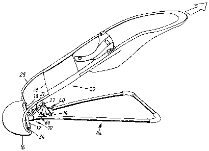
Figure 1 illustrates a bouncing cradle comprising a back-
rest 20, which is formed of a generally U-shaped frame
part 25 on which a cloth bag is to be pulled on so as to
form a reclining support for an infant. (In Figure 1, the
bag is shown not fully pulled on, for reasons of lucidity.
On the cloth bag, a pair of cloth trousers is shown, into
which the child should be put down).
The backrest frame 25 is supplemented by two straight and
axially aligned frame pieces 24 and a generally U-shaped
yoke integratedly attached between the same.
The frame pieces 24 are received in a pivot mounting 12
along a straight edge 13 of a support plate 16 belonging
to a base frame 10, which is intended to stably rest on a
CA 02654690 2008-12-08
WO 2008/004958 PCT/SE2007/000675
horizontal underlay. An essentially flat yoke of a gener-
ally triangular nature has the free ends 66 thereof paral-
lel to and attached in the support plate. At a distance
from the ends 66, the yoke is widened so as to form two
5 support points, which are laterally spaced-apart in rela-
tion to the backrest 20. Said two support points may be
established by friction material applied on the underside
of the yoke in the corner areas of the yoke between the
web and the branches. The support plate 16 may, on the
underside along the circumference border thereof, be pro-
vided with a strand of friction material, for instance
rubber, as anti-skid protection.
It can be seen that a bar 14 extends between the yoke ends
66, the bar 16 being received in the respective hole in
the yoke end parts.
An adjustment fitting 40 has a pivot mounting 23 for the
web part 22 of the U-shaped part of the backrest frame.
From Figures 2 and 6, it can be understood that the bar 14
and the arm 22 are approximately at the same distance from
the pivot mounting 12, and that the adjustment fitting 40
has an elongate opening 60 having a side 60, which is
turned obliquely downward and facing the first pivot
mounting 12 and in which recesses 51, 52, 53 are situated.
Each recess has a bottom part 62 that supports the bar 14,
and a mouth portion 63 that, obliquely downward and toward
the first pivot mounting, mouths in the opening 60. The
bar 14, the arm 22 and the pivot mountings 12, 23 are axi-
ally parallel.
The elongate opening 60 is delimited toward the upper end
thereof by a locking arm 70, which is pivotally mounted
CA 02654690 2008-12-08
WO 2008/004958 PCT/SE2007/000675
6
around a spindle 71 in the vicinity of the pivot mounting
23, and is biased by a spring 72 toward the end position
shown.
By the inclinations accounted for, the bar 14 can always,
from the opening 60, slide on surfaces inclined to the
vertical into the bottom portion 62 of a recess, when the
backrest is loaded vertically. From Figure 6, it is possi-
ble to further see that the mouth portion 63 of the recess
has a width that is greater than the diameter of the bar
14, and that the bottom portion 62 of the recess at the
upper part thereof is undercut in order to stably receive
the bar 14 and prevent the bar 14 from sliding out of the
recess, when the backrest is vertically loaded, independ-
ently of which recess the bar 14 is received in.
From Figure 6, it can be seen that the locking arm 70 in
the shown end position thereof, by the side thereof facing
the opening 60, intersects the upper mouth wall of the
recess 51 and forms a guide surface for the introduction
of the bar 14 from the opening 60 into the mouth part of
the recess 51.
By means of a bias spring 73, the locking arm 70 is biased
against a stopper 74. The arm 70 can be turned manually
against the action of the spring 73 and, in doing so,
brings the opening 60 in communication with an additional
elongate opening 80 in the fitting 40, the opening 80
extending up to the area of the pivot mounting 23.
Furthermore, it can be seen that on the outside thereof,
the fitting 40 has a gripping ear 90, which facilitates
manual turning of the fitting 40 around the mounting 22,
23. Figure 3 illustrates that the bar 14 is in the recess
CA 02654690 2008-12-08
WO 2008/004958 PCT/SE2007/000675
7
52, and that it is desirable to convert the bouncing cra-
dle into a transportation position in which the backrest
is generally parallel and next to the base frame 10. In
doing so, the locking arm 70 is turned back against the
5' action of the spring 73 in the direction of the arrow
indicated in Figure 3, so that the fitting 40 can be
turned in such a manner that the bar 14 leaves the recess
52 and runs along the opening 60 and inward toward the
opening 80, such as is indicated by the arrow in Figure 4.
Upon continued turning of the fitting 40 around the mount-
ing 22, 23, the turning motion of the fitting 40 is con-
tinued according to Figure 4 until the fitting 40 assumes
the position shown in Figure 5, in which the pivot mount-
ing 23 is situated in the vicinity of the bar 14 (not
shown), the bouncing cradle having assumed the transporta-
tion position. In the transportation position, the U-yoke
part 37 extends at an angle under the plane of the base
frame 10, and the web 22 thereof is situated on a level
under the bar 14.
Figure 7 illustrates that the support plate 16 has a pair
of integrated sleeves 85, which receive the ends 66 of the
yoke 84. Furthermore, it is seen that the sleeves 85 as
well as the yoke ends 66 have vertically aligned through
holes, and that a bolt joint extends therethrough. The
bolt joint is shown to have a nut at the top and has a
screw head at the bottom. The straight front edge 13 of
the support plate has a groove that receives the straight
frame pieces 24. The U-yoke part 37, the bottom web of
which forms the arm 22, is carried by the frame pieces 24
via the pair of arms 21.
The screw heads 86 of the bolt joints confine the straight
frame pieces 24 in the grooves in the support plate 16.
CA 02654690 2008-12-08
WO 2008/004958 PCT/SE2007/000675
8
The integrated sleeves 85 afford a stable high-strength
connection to the support plate 16, and afford, by means
of the bolt joints, a simple connection of the yoke 84 to
the support plate 16. From Figure 7, it is possible to
further see that the support plate has integrated buttons
28 that, in addition to confining the frame pieces 24,
also afford anchorage of the lower border part of the bag
that is threaded onto the frame part 25 for the formation
of the backrest 20. In that connection, the front part of
the bag has buttonhole openings in alignment with the but-
tons 28, whereby a stable anchorage of the bag in the
stretched state is attained.
From Figures 7 and 8, it can be seen that the support
plate 16 has a projecting U-girder 110, which is situated
between the sleeves 85 and is integrated with the injec-
tion-moulded support plate 16. The bottom web 111 of the
girder 110 is situated at the topside of the support
plate, and the branches 112 thereof extend downward there-
from. The distance between the outsides of the branches is
somewhat smaller than the free distance between the branch
arms 21 of the U-yoke 37. In this way, the U-yoke 37 is
centred and thereby the backrest 20 in relation to the
base frame, when the U-yoke is turned down over the U-
girder. By the fact that the free branch ends of the
girder 110 have generally wedge-shaped protuberances or
noses 115 at least at the free end of the girder, an
interference between said protuberances 115 and the arms
21 is afforded, and the arms 21 are locked detachably
under said protuberances 114 when the arms 21 have passed
past them. The branches 112 are elastically resilient and
also allow, thanks to a wedge surface 113, a turning back
of the U-yoke piece 37 past the arms 21, so that the
branches are driven toward each other upon the turning
CA 02654690 2008-12-08
WO 2008/004958 PCT/SE2007/000675
9
back of the U-yoke 37 away from the transportation posi-
tion. That is, the branch ends having the wedge surfaces
113, 114 form a detachable catch for the retention of the
backrest next to the base frame in the transportation
position.
Finally, from Figure 6, it can be understood that the
recesses 51, 52, 53 allow free passage of the bar 14 to
and from the bottom portion 62, with the exception of a
small dog 64 possibly being arranged at the transition
between the mouth portion 63 and bottom part 62 of the
recess in the upper wall of the recess. Said dog 64 forms,
together with the opposite recess wall, a waist that is
somewhat smaller than the diameter of the bar 14. Thanks
to an elastic resiliency of the opposite walls of the
recess in the vicinity of said dog 64, a snap-locking
function is afforded that blocks the bar 14 from uninten-
tionally leaving the bottom part 62 of the recess. The
undercut of the upper side wall of the recess in the bot-
tom part serves to guarantee that the bar 14 cannot leave
the recess upon loading of the backrest in the direction
of the base f rame .
The upper side wall of the recess leans at an angle R<
90 to the line 29 between the centres of the bar 14 and
of the arm part 22. The lower side wall of the recess
leans, as is seen from Figure 6, at an angle a > 90 to
the line 29.
By the fact that the upper wall of the elongate opening 60
has a substantial inclination to the horizontal, independ-
ently of the position of the bar 14 along the opening 60,
the bar 14 will be able to slide along the upper smooth
opening wall, when the backrest is loaded. When the bar 14
CA 02654690 2008-12-08
WO 2008/004958 PCT/SE2007/000675
then is introduced into a recess 52, 53, the bar will 14
easily slide along the upper smooth mouth wall of the
recess, which also has a substantial inclination to the
horizontal, and passes into the bottom part 62 of the
5 recess. Hence, the bar 14 automatically makes for one of
the recesses 51-53 upon loading of the backrest.
From Figures 7-9, it is possible to further see that each
sleeve 85 has a nut socket 87, which rotationally secures
10 a lock nut that receives a through screw, the head of
which radially projects from the diametrically opposed
side of the sleeve and screens off the groove in order to
locally restrain a straight frame piece 24 therein. At the
other end of the frame piece, the same is restrained in
the groove by a respective dog 64. The screw is suitably
of the Allen-type and the nut 87 is suitably a lock nut
having friction inserts.