Language selection

Search

Patent 2654992 Summary

Third-party information liability

Some of the information on this Web page has been provided by external sources. The Government of Canada is not responsible for the accuracy, reliability or currency of the information supplied by external sources. Users wishing to rely upon this information should consult directly with the source of the information. Content provided by external sources is not subject to official languages, privacy and accessibility requirements.

Claims and Abstract availability

Any discrepancies in the text and image of the Claims and Abstract are due to differing posting times. Text of the Claims and Abstract are posted:

  • At the time the application is open to public inspection;
  • At the time of issue of the patent (grant).
(12) Patent: (11) CA 2654992
(54) English Title: BUILDING WALL STRUCTURES AND THEIR COMPONENTS
(54) French Title: CONSTRUCTION DE STRUCTURES MURALES ET DE LEURS ELEMENTS
Status: Granted and Issued
Bibliographic Data
(51) International Patent Classification (IPC):
  • E04C 02/40 (2006.01)
  • E04B 02/18 (2006.01)
  • E04B 02/86 (2006.01)
  • E04C 02/20 (2006.01)
(72) Inventors :
  • HOLROYD, LESLIE STEWART (Canada)
(73) Owners :
  • NUFORM BUILDING TECHNOLOGIES INC.
(71) Applicants :
  • NUFORM BUILDING TECHNOLOGIES INC. (Canada)
(74) Agent: STIKEMAN ELLIOTT LLP
(74) Associate agent:
(45) Issued: 2011-08-23
(22) Filed Date: 2009-02-20
(41) Open to Public Inspection: 2010-08-20
Examination requested: 2009-04-17
Availability of licence: N/A
Dedicated to the Public: N/A
(25) Language of filing: English

Patent Cooperation Treaty (PCT): No

(30) Application Priority Data: None

Abstracts

English Abstract

A rectilinear extruded plastic wall forming panel characterized being able to directly connect to next adjoining panels either by sliding adjoining panels together or by pushing them together. Also, if one of the panel walls is to become an exterior wall, it is preferably reinforced, for example with pultruded fiberglass or foamed PVC.


French Abstract

Mur rectiligne en matière plastique extrudée formant un panneau caractérisé par sa capacité d'être directement relié aux panneaux suivants adjacents soit en glissant ensemble des panneaux adjacents soit en les poussant ensemble. De plus, si un des murs du panneau doit devenir un mur extérieur, il est de préférence renforcé, par exemple, par de la fibre de verre pultrudée ou du PVC expansé.

Claims

Note: Claims are shown in the official language in which they were submitted.

CLAIMS:
1. A wall forming panel comprising an integral elongated enclosed extrusion of
thermal
plastic material, said panel having means for connecting to an adjoining panel
on two
sides thereof, said means comprising an inwardly projecting groove running the
length
of said panel at each side of said panel adjacent a first end of said panel,
and having at
each side of said panel at a second end of said panel a projecting arm having
a measure
of resiliency provided with an in-turned end or finger running the length of
said panel,
the arrangement being such that the finger of each said projecting arm is
adapted to be
received in a corresponding groove of a next adjoining panel either by a
sliding or
pushing motion, and a projecting ridge adjacent each groove on which the
projecting
arm of an adjoining connected panel bears to restrict passage of moisture and
other
agents, wherein the length of each finger is less than the distance from the
top of a
projecting ridge to the bottom of an adjacent groove whereby, when connected
to an
adjoining panel, to define a gap between the end of a finger and the bottom of
the
groove.
2. A wall forming panel as claimed in claim 1 in which said projecting ridge
is an
upward extension of the wall of the groove adjacent said first panel end.
3. A wall forming panel as claimed in claim 2 in which said ridge defines a
wedging
surface to cant the finger passing over said ridge outwardly from its in-
turned position.
4. A wall forming panel as claimed in claim 1 having a wall which is to become
an
exterior wall when said panel is assembled with other panels reinforced.
-8-

5. A wall forming panel as claimed in claim 4 in which said exterior wall is
reinforced
with pultruded fiberglass.
6. A wall forming panel as claimed in claim 5 in which the pultruded
fiberglass is a
layer of pultruded fiberglass bonded to said exterior wall.
7. A wall forming panel as claimed in claim 5 in which the pultruded
fiberglass
comprises pockets of pultruded fiberglass bonded to said exterior wall.
8. A wall forming panel as claimed in claim 4 in which said exterior wall is
reinforced
with foamed PVC.
9. A wall forming panel as claimed in claim 1 wherein the panel is formed of
one of the
materials chosen from PVC or reprocessed thermoplastic, the length of the arms
is in
the range of about 1/2 inch to 1 inch, the thickness of the arms is in the
range of about
0.08 inch to about 0.1 inch and the length of the fingers is in the range of
about 0.110
inch to about 0.230 inch.
10. A wall forming panel as claimed in claim 9 wherein the length of the arms
is about
3/4 inch and the length of the fingers is in the range of about 0.130 inch to
about 0.160
inch.
11. A wall forming panel as claimed in claim 1 which further comprises a
locking
arrangement between cooperating surfaces of the grooves and fingers.
-9-

Description

Note: Descriptions are shown in the official language in which they were submitted.


CA 02654992 2009-02-20
13459CA
TITLE: BUILDING WALL STRUCTURES AND THEIR COMPONENTS
FIELD OF THE INVENTION
This invention relates to novel wall structures for housing and other
buildings
and novel components therefore.
BACKGROUND OF THE INVENTION
More particularly, the invention relates to the creation of a wall structure
of
confined, poured concrete (which in some cases is or may be fully insulated
at the time of the erection), such as illustrated in U.S. Patent 6,212,845 B1.
In such prior art, illustrated by the said U.S. Patent, a wall structure was
created by wall forming panels indicated at 5 in the said U.S. Patent joined
by
box connectors indicated at 6 in the said U.S. Patent.
Because such panels and box connectors were formed from different
extrusions it was difficult to match colour of the panels and the box
connectors with the result of the wall formed by their connection showed an
exterior and interior wall of contrasting colours which was offensive to the
eye.
It is one object of the present invention to eliminate this visually
undesirable
feature.
Another important object of the invention is to eliminate the need for any
form of separate connector pieces, such as the prior art box connectors of the
said U.S. Patent, to connect adjoining wall forming panels. Use of wall-
-1-

CA 02654992 2009-02-20
13459CA
forming panels according to the invention thus reduces, as compared to the
prior art, the number of wall-forming components necessary to erect a wall
structure, with attendant savings in manufacturing, inventory, installation
and other costs. This reduction of components depends on the length of the
wall.
It will be understood that the size of the panels used is limited by the
ability
of the workmen to handle them.
Another important object of the invention is to provide wall panel
connections such that the panels can be joined by either vertical sliding
assembly or by lateral push snap-fit assembly.
Another object of the invention is to provide panel connections which reduce
or block air, vapour, moisture and other agents from seeping into the
connection between adjoining panels thereby improving the thermal
performance and weather resistance of the connections and wall structures.
These and other features of the invention will become apparent from the
following description given with reference to the accompanying drawings in
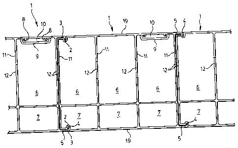
which Figure 1 is a plan view of the panels of the present invention showing
the connections between adjoining panels;
Figure 2 a is a cross-section enlargement of one form of connection between
adjoining panels wherein a projecting bearing ridge or projection at the
entrance to the groove provided to receive the in-turned flange at the end of
the next connecting panel;
Figure 3 is a cross-section enlargement of an alternative form of connection
between adjoining panels in accordance with the invention;
Figure 4 is a broken away perspective view illustrating the assembly of a wall
-2-

CA 02654992 2009-02-20
13459CA
forming panel with other panels by vertical sliding movement;
Figure 5 is a part diagrammatic cross-sectional view illustrating the assembly
of panels through a pushing snap-fit connection;
Figure 6 is a perspective view of a panel according to the invention for use
in
making solid concrete walls;
Figure 7 is a perspective view of a panel similar to the panels shown in
Figure
4 but has an exterior wall reinforced with a layer of pultruded fiberglass;
Figure 8 is a perspective view of a panel similar to the panels shown in
Figure
4 but has an exterior wall reinforced with pockets of pultruded fiberglass;
Figure 9 is a perspective view of a panel similar to the panels shown in
Figure
4 but has an exterior wall reinforced with a layer of foamed PVC; and,
Figure 10 is a cross-section enlargement of an alternative form of connection
between adjoining panels in accordance with the invention.
DETAILED DESCRIPTION OF THE PREFERRED EMBODIMENTS
With reference to Figures 1 and 2, the panels 1 illustrated are connected
according to the invention with each panel having adjacent one end a groove
2. At the edge of groove 2 is a projecting ridge 3. At the end of each panel 1
opposite to the groove 2, the panel 1 is provided with a short in-turned
flange
or finger 4 at the end of a projecting arm 5. The projecting arm 5 has a
measure of flexibility such that the flange or finger 4 can be flexed
outwardly
to pass over ridge 3 and snap back into groove 2 (as shown in Figure 5).
Groove 2 is preferably of a depth that there is a gap 2a between the bottom of
finger 4 and the bottom of groove 2.
Such flexibility is affected by both the choice of materials as well as the
dimensions of the components. For example, for typical substrate materials
such as PVC or reprocessed thermoplastic, it has been found that, if the
length

CA 02654992 2009-02-20
13459CA
of arm 5 is in the range of about 1/2 inch to about 1 inch, and preferably
about
3/4 inch, and the thickness of arm 5 is in the range of about 0.08 inch to
about
0.1 inch, then adequate flexibility is achieved while retaining sufficient
strength and integrity.
When finger 4 is engaged with groove 2, arm 5 presses down on ridge 3
thereby establishing a sealing arrangement therebetween which reduces or
blocks the passage of air, vapour, moisture or other agents through the
connection. Having a gap 2a between the bottom of finger 4 and the bottom
of groove 2 helps to ensure that the sealing arrangement is as tight as
possible.
As shown in all Figures except Figure 3, the ends of fingers 4 and ridges 3
may be rounded. Alternatively, as shown in Figure 3, they may be angled.
The cooperating shapes of the end 4a of finger 4 and the corner portion 25 of
adjacent panel 1 are such that as the two panels 1 are brought into snap-fit
connection arms 5 are forced outwardly (as shown in Figure 5) by wedging
action. In the embodiments shown in all Figures (except Figure 3), this is
achieved by providing finger end 4a with a rounded shape and enhanced by
providing corner 26 of corner portion 25 with a rounded shape as well. In the
embodiment shown in Figure 3, finger end 4a' is provided with an angled,
wedge-like shape; ridge 3' may also be provided with a cooperating angled
wedge-like shape.
In yet a further embodiment, as shown in Figure 10, corner portion 25' of
panel 1 is provided with an angled face 27 to assist in the wedging action as
the two panels 1 are brought into snap-fit connection.
-4-

CA 02654992 2009-02-20
13459CA
Preferably, the length of fingers 4 is such that when fingers 4 of one panel I
are brought into initial contact with the corner portion 25 of a neighbouring
panel 1 wedging action may begin immediately as the two panels are snap-fit
together.
Groove 2 and finger 4 define cooperating locking means 30 to resist
disconnection of two connected panels 1. In the illustrated embodiments,
locking means 30 comprises groove wall or surface 2b (or 2b' in Figure 3) and
finger surface 4b (or 4b' in Figure 3) oriented transversely to the direction
of
disconnection (arrow B in Figures 2 and 3). Other locking means may be
used. In such an arrangement, ridge 3 (or 3') may comprise an upward
extension of the groove wall 2b (or 2b').
In operation, as shown in Figure 5, adjacent panels I may be manually snap-
fitted together by moving them together in the direction indicated by arrow
A. As fingers 4 engage ridges 3, arms 5 flex outwardly to allow fingers 4 to
ride up and over ridges 3 and then snap down into grooves 2. It has been
found that if the length of fingers 4 is too short, then connected panels 1
may
disengage too easily. On the other hand, if the length of the fingers 4 is too
great, then it is difficult to achieve a manual snap-fit. For example, in such
circumstance, to achieve a snap-fit, tools (such as a pry bar and/or a hammer)
may have to be used and in the use thereof one or both panels 1 may be
damaged. Or, the mere attempt to force a snap-fit with fingers 4 that are too
long may damage fingers 4 and/or arms 5.
It has been found that for typical substrate materials such as PVC or
reprocessed thermoplastic, an arm length for arm 5 in the range of about 'h
inch to about 1 inch, and preferably about 3/4 inch, and an arm thickness for
-5-

CA 02654992 2009-02-20
13459CA
arm 5 in the range of about 0.08 inch to about 0.1 inch and fingers 4 with a
length in the range of about 0.110 inches to about 0.230 inches are workable.
More preferably, the length of fingers 4 would be in the range from about
0.130 to about 0.160 inches.
As an alternative to snap-fitting as described above, as shown in Figure 4,
adjacent panels 1 may be connected by vertically sliding them together.
While the panels 1 shown in Figure 1 are provided with main concrete
receiving compartments 6 and compartments 7 which may contain or can be
filled with insulating material at the building erector's choice, it will be
understood that the connection of the panels would equally apply to panel 1'
shown in Figure 6 which is provided only with concrete receiving
compartments 6. It will be appreciated that, with respect to a wall made of
panels 1', if insulation is required, separate insulation may be independently
applied, for example to either or both sides of such wall.
Each of the concrete receiving compartments 6 may be provided with a pair of
inwardly projecting and outwardly turned guide members 8 over which may
be sleeved a sleeve member 9 (Figure 1) to provide a channel 10 isolated from
concrete poured within the compartments 6 to receive wiring or other services
all as shown in U.S. Patent 6,212,845 131.
It will be understood that the panel walls 11 or the portions of such walls
which confront the concrete receiving compartments 6 will be provided with
openings 12 to provide for the ready flow of concrete between adjoining
concrete receiving compartments 6 all as shown in the said U.S. Patent.
-6-

CA 02654992 2009-02-20
13459CA
It will also be understood that the exterior walls 19 of panel 1 (and of panel
1',
Figure 6), may be provided with any requisite coating usually a coextruded
coating to protect against ultra-violet rays and the like.
Figure 7 shows a panel 13 which is similar to panels 1 except that it has an
exterior wall 14 reinforced with a layer 15 of pultruded fiberglass.
Similarly, Figure 8 shows the use of pultruded fiberglass pockets 16 to
reinforce an exterior wall 17 of a panel 18 otherwise similar to panel 1.
Similarly, Figure 9 shows the use of foamed PVC 20 to reinforce an exterior
wall 21 of a panel 22 otherwise similar to panel 1.
While various preferred embodiments of the present invention have been
described herein in detail, it will be appreciated that variations may be made
thereto without departing from the spirit of the invention or scope of the
appended claims.
-7-

Representative Drawing
A single figure which represents the drawing illustrating the invention.
Administrative Status

2024-08-01:As part of the Next Generation Patents (NGP) transition, the Canadian Patents Database (CPD) now contains a more detailed Event History, which replicates the Event Log of our new back-office solution.

Please note that "Inactive:" events refers to events no longer in use in our new back-office solution.

For a clearer understanding of the status of the application/patent presented on this page, the site Disclaimer , as well as the definitions for Patent , Event History , Maintenance Fee  and Payment History  should be consulted.

Event History

Description Date
Change of Address or Method of Correspondence Request Received 2024-01-30
Maintenance Request Received 2024-01-30
Inactive: Office letter 2023-12-08
Revocation of Agent Request 2023-12-05
Revocation of Agent Requirements Determined Compliant 2023-12-05
Appointment of Agent Requirements Determined Compliant 2023-12-05
Appointment of Agent Request 2023-12-05
Inactive: Office letter 2022-05-02
Revocation of Agent Request 2022-03-22
Revocation of Agent Requirements Determined Compliant 2022-03-22
Appointment of Agent Requirements Determined Compliant 2022-03-22
Revocation of Agent Requirements Determined Compliant 2022-03-22
Appointment of Agent Requirements Determined Compliant 2022-03-22
Change of Address or Method of Correspondence Request Received 2022-03-22
Appointment of Agent Request 2022-03-22
Common Representative Appointed 2019-10-30
Grant by Issuance 2011-08-23
Inactive: Cover page published 2011-08-22
Inactive: Final fee received 2011-06-10
Pre-grant 2011-06-10
Letter Sent 2011-05-04
Notice of Allowance is Issued 2011-05-04
Inactive: Approved for allowance (AFA) 2011-04-28
Amendment Received - Voluntary Amendment 2011-01-24
Application Published (Open to Public Inspection) 2010-08-20
Inactive: Cover page published 2010-08-19
Inactive: S.30(2) Rules - Examiner requisition 2010-07-22
Inactive: Office letter 2009-09-14
Letter Sent 2009-09-14
Inactive: Single transfer 2009-07-28
Letter Sent 2009-05-22
Amendment Received - Voluntary Amendment 2009-05-06
Inactive: IPC assigned 2009-05-06
Inactive: First IPC assigned 2009-05-06
All Requirements for Examination Determined Compliant 2009-04-17
Request for Examination Requirements Determined Compliant 2009-04-17
Request for Examination Received 2009-04-17
Inactive: Filing certificate - No RFE (English) 2009-03-20
Application Received - Regular National 2009-03-20

Abandonment History

There is no abandonment history.

Maintenance Fee

The last payment was received on 2009-04-17

Note : If the full payment has not been received on or before the date indicated, a further fee may be required which may be one of the following

  • the reinstatement fee;
  • the late payment fee; or
  • additional fee to reverse deemed expiry.

Patent fees are adjusted on the 1st of January every year. The amounts above are the current amounts if received by December 31 of the current year.
Please refer to the CIPO Patent Fees web page to see all current fee amounts.

Owners on Record

Note: Records showing the ownership history in alphabetical order.

Current Owners on Record
NUFORM BUILDING TECHNOLOGIES INC.
Past Owners on Record
LESLIE STEWART HOLROYD
Past Owners that do not appear in the "Owners on Record" listing will appear in other documentation within the application.
Documents

To view selected files, please enter reCAPTCHA code :


To view images, click a link in the Document Description column. To download the documents, select one or more checkboxes in the first column and then click the "Download Selected in PDF format (Zip Archive)" or the "Download Selected as Single PDF" button.

List of published and non-published patent-specific documents on the CPD .

If you have any difficulty accessing content, you can call the Client Service Centre at 1-866-997-1936 or send them an e-mail at CIPO Client Service Centre.


Document
Description 
Date
(yyyy-mm-dd) 
Number of pages   Size of Image (KB) 
Description 2009-02-19 7 257
Abstract 2009-02-19 1 10
Drawings 2009-02-19 9 229
Claims 2009-02-19 2 66
Drawings 2009-05-05 9 210
Representative drawing 2010-07-25 1 10
Claims 2011-01-23 2 70
Representative drawing 2011-07-19 1 11
Description 2011-11-27 7 257
Maintenance fee payment 2024-01-29 3 93
Change to the Method of Correspondence 2024-01-29 3 93
Filing Certificate (English) 2009-03-19 1 156
Acknowledgement of Request for Examination 2009-05-21 1 175
Courtesy - Certificate of registration (related document(s)) 2009-09-13 1 102
Commissioner's Notice - Application Found Allowable 2011-05-03 1 164
Change of agent 2023-12-04 5 124
Courtesy - Office Letter 2023-12-07 2 208
Courtesy - Office Letter 2023-12-07 2 213
Correspondence 2009-09-13 1 16
Correspondence 2011-06-09 1 39
Maintenance fee payment 2021-02-15 1 25
Change of agent / Change to the Method of Correspondence 2022-03-21 4 118
Courtesy - Office Letter 2022-05-01 1 186
Courtesy - Office Letter 2022-05-01 1 192