Note: Descriptions are shown in the official language in which they were submitted.
CA 02655517 2008-12-16
WO 2008/005679 PCT/US2007/071463
TURBOCHARGER PERFORMANCE QUALIFICATION METHOD AND
APPARATUS
Field of the Invention
[0001] This invention relates to internal combustion engines, including but
not limited
to characterization of engine components, specifically, characterization of
turbocharger performance.
Background of the Invention
[0002] There are numerous instances when a performance of a turbocharger may
require qualification. For example, newly manufactured turbocharger units may
require a performance test at the manufacturer' facility, or another facility,
for a
determination of whether there are any performance defects, or whether the
turbochargers conform to their functional specifications. In other instances,
turbochargers that have undergone a remanufacturing or reconditioning process
may also require testing to qualify their performance. In yet other instances,
turbocharger performance may require qualification in a service or testing
environment as part of an engine troubleshooting process. In any of these
instances, various performance parameters of a sample turbocharger unit may be
acquired through testing and analyzed.
[0003] Techniques previously used for turbocharger performance qualification
have
included acquisition of various data points within an operational range of a
turbocharger for the compilation of a turbine or compressor map, i.e., two
dimensional plots of curves representing turbine or compressor performance
plotted
against a mass flow through the turbine or compressor versus a pressure ratio
across the turbine or compressor. Typically, a map is a collection of 20 - 70
1
CA 02655517 2008-12-16
WO 2008/005679 PCT/US2007/071463
individual running data points that are connected to form curves of constant
shaft
speed and surge. With interpolation, islands of efficiency are plotted over
the
curves. These turbine or compressor maps are typically overlaid over what is
considered a typical map, to yield a determination of adequacy of a device's
performance through visual observation and estimation of the overlay.
Interpretation
of the results is subjective and does not provide reasonable data to check
individual
turbo performance.
[0004] Such techniques are not practical to implement in a production
environment,
and even if spot checking is made on sample pieces of a production line, the
performance qualification of a turbocharger or one of its components is
incomplete
and may also be inaccurate as it is based on a visual determination. Moreover,
these known techniques are data intensive in compiling the performance maps,
time
intensive, and costly to implement.
[0005] Accordingly, there is a need for an improved method of qualifying
performance for turbochargers, that is accurate, does not depend on a
subjective
determination, and that does not require vast amounts of data to be collected.
Summary of the Invention
[0006] A method for qualifying turbocharger performance that is accurate, does
not
depend on a subjective determination, and that does not require vast amounts
of
data to be collected includes the step of operating a turbocharger at a single
test
condition. A set of data may be acquired from a set of operating parameters of
the
turbocharger operating at the test condition. The set of data acquired may be
compared to a set of operating ranges that are deemed acceptable, and a
determination may be made as to whether the set of data falls within the
acceptable
operating ranges. Performance of the turbocharger may then be qualified based
on
an outcome of the determination.
2
CA 02655517 2008-12-16
WO 2008/005679 PCT/US2007/071463
[0007] In one embodiment, a turbocharger may be operated on an engine at a
test
condition as part of an engine system. A set of inputs to the system that
includes a
fuel consumption rate of the engine system may be monitored during the test. A
set
of outputs from the system that includes a compressor outlet pressure of the
turbocharger may also be monitored. The set of outputs may be compared to a
set
of respective acceptable ranges, and a finding of acceptable performance of
the
turbocharger may be made when the set of outputs is within the set of
respective
acceptable ranges.
[0008] A test station for qualifying turbocharger performance in a
manufacturing or
remanufacturing environment and may include a test fixture having a
turbocharger
mounting apparatus attached thereon, an electronic controller associated
therewith,
a plurality of sensors that are disposed to measure operating parameters of
the test
station and are operably connected to the test station, and a fluid pump
arranged
and constructed to fluidly connect to a turbocharger at times when the
turbocharger
is connected to the test fixture with the mounting apparatus, such that a
fluid pump
outlet is connected to a turbine inlet passage.
Brief Description of the Drawings
[0009] FIG. 1 is a block diagram of an engine having a turbocharger associated
therewith.
[0010] FIG. 2 is a graph containing overlaid data for multiple turbochargers.
[0011] FIG. 3 is a graph for plotting information relating to a qualification
determination of multiple turbochargers in accordance with the invention.
3
CA 02655517 2008-12-16
WO 2008/005679 PCT/US2007/071463
[0012] FIG. 4 is a flowchart for a method of analytically qualifying
turbocharger
performance in accordance with the invention.
[0013] FIG. 5 is a flowchart for a method of graphically qualifying
turbocharger
performance in accordance with the invention.
[0014] FIG. 6 is a block diagram of a test station for testing and qualifying
turbocharger performance in accordance with the invention.
[0015] FIG. 7 is a graph for a distribution used to qualify turbocharger
performance
in accordance with the invention.
Description of a Preferred Embodiment
[0016] The following describes an apparatus for and method of qualifying the
performance of turbochargers. Some of the examples described herein deal with
methods for qualifying turbochargers or individual components thereof for use
on
internal combustion engines, but these methods advantageously have general
applicability to any type of turbine and/or compressor devices used on other
applications.
[0017] A typical configuration of an engine 100 having a turbocharger 102
associated therewith is shown in block diagram form in FIG. 1. The
turbocharger
102 may include a compressor 104 connected to a turbine 106 as is known. A
flow
of air 108 may enter the compressor 104 during operation of the turbocharger
102,
where it is compressed. A flow of compressed air, along with a flow of fuel
110, may
enter the engine 100 where the two flows may be mixed and combusted to yield a
power output 112 of the engine 100. A flow of exhaust gas may exit the engine
100
and be routed to the turbine 106, where it may be expanded to provide work
thereto
to operate the compressor 104 before being expelled to the environment as a
flow of
4
CA 02655517 2008-12-16
WO 2008/005679 PCT/US2007/071463
low pressure exhaust gas 114. During operation of the engine 100 and the
turbocharger 102 and for a specific operation condition, the flow of air 108
may have
a mass flow rate, ml, at a compressor outlet pressure, P1, and a compressor
inlet
pressure, P2. Similarly, the flow of exhaust gas 114 may have a mass flow
rate, m2,
and be at a pressure, P3, at the inlet of the turbine 106, and at a pressure,
P4, at the
outlet of the turbine 106. When, for example, qualification of the performance
of the
compressor 104 is desired, the mass flow ml along with the pressures P1 and P2
may be acquired for a range of operating conditions of the engine 100, and
plotted
on a compressor map. Typically, data for more than one compressor may be
overlaid onto a compressor map of a nominal compressor.
[0018] A typical compressor map overlay that is similar to a map overlay
typically
used to qualify the performance of a compressor or a turbine is shown in FIG.
2.
The compressor map overlay shown in FIG. 2 includes a set of data points,
represented by crossed-circle points 200 and connected by long-dashed lines
201,
which represent a performance of a nominal compressor. Overlaid thereon is a
second set of points, represented by triangles 202 and connected by solid
lines 203,
which represent a performance of a second compressor that is not the nominal
compressor, and a third set of points, represented by squares 204 and
connected by
short-dashed lines 205, which represent a performance of a third compressor
that is
also not the nominal compressor. There are only 15 total test points
represented in
this graph for each compressor, for the sake of clarity, although a typical
map
overlay may include 20-70 total test points for each compressor being
evaluated.
[0019] The series of points 200, 202, and 204, are acquired under similar
operating
conditions. A visual determination on the performance of each compressor
tested
typically involves a determination on the spread of each of the points 200,
202, and
204. Under some conditions, groupings of points may be closely associated to
each
other, for example, a grouping 206. The points within the grouping 206 may be
closely associated to each other enough to warrant a determination that the
performance of each of the compressors that yielded those points is
satisfactory
CA 02655517 2008-12-16
WO 2008/005679 PCT/US2007/071463
when compared to the nominal compressor. Under some other conditions, though,
groupings of points on the same overlay may not be closely associated to each
other, for example a grouping 208.
[0020] The points within the grouping 208 may be spread apart enough to
warrant a
determination that the performance of each of the compressors that yielded
those
points is not satisfactory when compared to the nominal compressor. In a case
similar to the one shown groupings similar to the groupings 206 and 208 appear
on
the same overlay, a subjective overall determination as to the performance of
each
compressor tested may be made. As described above, such a determination is
data
intensive, time consuming, costly, and may not conclusively determine
acceptability
of a compressor being tested because it is based on the subjective judgment of
the
person reviewing the data. Moreover, a qualification of a turbocharger unit
depends
on the separate determinations made individually for the compressor and
turbine
that make up each turbocharger, further removing the determination comparison
between the performance of the entire turbocharger unit from that of a nominal
turbocharger.
[0021] These issues and others may be addressed by the method of qualifying
the
performance of a turbocharger as described herein. A graph showing an
alternative
and improved method of objectively determining performance acceptability of
not
only a single turbocharger component, but advantageously determining
performance
acceptability of an entire turbocharger unit, is shown in FIG. 3. A horizontal
axis 302
represents an energy input parameter into a system. In the example described
here,
an entire engine may be considered as the system, and a rate of fuel
consumption,
in lbs/hr, may be considered as the energy input thereto. Of course other
combinations may be considered, for example, the turbocharger unit may be the
system for a bench test, or an enthalpy input may be calculated and considered
as
the energy input. Other hardware combinations or energy parameters may be
used.
A selection of the hardware and parameters used for this consideration may
depend
largely on the purpose of the qualification, for example, an engine
manufacturer
6
CA 02655517 2008-12-16
WO 2008/005679 PCT/US2007/071463
interested in testing engine systems while monitoring fuel consumption may use
the
same or similar parameters as those used to compile the graph shown in FIG. 3,
i.e.,
a fuel flow rate on the horizontal axis 302 versus a vertical axis 304 that
may be
used to express combined values, in this case, a compressor outlet pressure
and a
variable nozzle turbine (VNT) percent duty cycle.
[0022] The parameters selected for quantification and plotting purposes are
representative of an engine's controllable inputs and outputs. For example, a
controlled input to a compression ignition engine is a throttle position that
determines
a rate of fuel consumption and therefore an engine speed. Spark ignition
engines
operate in a similar fashion, but instead of a fueling, an airflow into the
engine that
operates under a substantially constant air to fuel ratio may be controlled to
control
engine speed by use of a throttle valve. One output that may be monitored on
an
engine that is indicative of turbocharger performance is compressor outlet
pressure,
which is also plotted on the graph of FIG. 3, although other parameters may
also be
used. Finally, the VNT duty cycle, as a controllable variable input to the
engine
system, may also be plotted on the graph of FIG. 3, but is optional and may be
assumed fixed for each experimental testing condition. In general, the engine
system is viewed as a complete system, with input parameters of fuel and air
entering the system, and a flow of exhaust gas and power exiting the system as
outputs.
[0023] The data plotted in the graph of FIG. 3 is representative of one method
of
qualifying the performance of turbocharger units. Data on one or more
turbocharger
units may be acquired for a first test condition 306 and a second test
condition 308.
Each of the test conditions 306 and 308 may be a single steady state point of
engine
operation, and may be selected as points that are representative of engine
operation
for optimization of performance and/or emissions. In the example shown here
for
illustration, the test condition 306 and/or the test condition 308 may
advantageously
be selected from a series of standard heavy-duty emissions testing mode
points.
The test condition 306 may be arranged to attain and engine speed of 2100
7
CA 02655517 2008-12-16
WO 2008/005679 PCT/US2007/071463
revolutions per minute (RPM) at a fuel consumption rate of about 100 lb/hr
(45.5
Kg/hr) to represent a medium to high load condition, while the test condition
308
may be arranged to attain about and engine speed of about 1000 RPM at a fuel
consumption rate of about 28 lb/hr (13 Kg/hr) to represent a low to medium
load
condition. Any other points of engine operation may advantageously be
selected.
[0024] In the example shown, data for a first, second, and third turbochargers
that
have been tested on the same or on advantageously different engines are
acquired
and plotted. Information on the first turbocharger is plotted using a hollow
circle
point 310 for the compressor's outlet pressure, and a filled-in circle 312 for
a duty
cycle for the variable nozzle turbine (VNT) setting during the test. The
points 310
and 312, as plotted, represent a boost pressure of about 124 inHg (420 kPa) at
a
VNT duty cycle of about 70%. Similarly, data on a second turbocharger is
plotted
using a hollow triangle point 314 for the compressor's outlet pressure, and a
filled-in
triangle 316 for a VNT duty cycle setting during the test. The points 314 and
316, as
plotted, represent a boost pressure of about 120 inHg (406 kPa) at a VNT duty
cycle
of about 70%. Lastly, data on the third turbocharger is plotted using a hollow
square
point 318 for the compressor's outlet pressure, and a filled-in square 320 for
a VNT
duty cycle setting during the test. The points 318 and 320, as plotted,
represent a
boost pressure of about 130 inHg (440 kPa) at a VNT duty cycle of about 70%.
[0025] Data may be plotted for the test condition 308 in a similar fashion and
using
the same plotting shapes as data plotted for the test condition 306. Hence,
point
322 may represent a boost pressure and point 324 may represent the VNT duty of
the first turbocharger, point 326 may represent a boost pressure and point 328
may
represent the VNT duty of the second turbocharger, and finally point 330 may
represent a boost pressure and point 332 may represent the VNT duty of the
third
turbocharger.
[0026] The data points 310 - 332 may advantageously be relied on for a
complete
qualification of each of the first, second, and third turbochargers being
evaluated.
8
CA 02655517 2008-12-16
WO 2008/005679 PCT/US2007/071463
This qualification may be made using known nominal and threshold ranges for
all
values of interest being plotted. In the graph of FIG. 3, the parameters
selected to
be of interest are compressor outlet pressure (boost) and VNT duty cycle. Each
of
these parameters may have a nominal range and allowable offsets of each of the
testing conditions being plotted. A nominal boost range for the test condition
306 is
represented by the dash-dot-dash line 334. The line 334 may be arranged to
represent a limited range of operating conditions to allow for minor
adjustments to
the desired fueling rate of the engine during testing, and may be slightly
slanted to
accommodate expected differences in output, in this case boost values, as a
result
of variations in an input parameter, in this case, engine fueling rate. The
line 334
may be used to generate a band defined by an upper limit line 336, and a lower
limit
line 338. The upper limit 336 and lower limit 338 lines may follow the nominal
line
334. An area 340 is shown shaded and defined between the upper limit line 336,
the lower limit line 338, and vertical lines that coincide with each end of
the nominal
line 334, may be used for a qualification of the boost generated by a
turbocharger
being tested.
[0027] Points falling within the area 340 may advantageously represent
turbochargers with acceptable performance characteristics, while points
falling
outside the area 340 may represent turbochargers falling above or below a
desired
performance characteristic range, i.e. turbochargers failing to pass a
qualification
determination.
[0028] Similar to the area 340, other areas may be considered around other
nominal
lines characterizing other parameters and/or testing conditions. For instance,
a
nominal line 342 may be defined as a nominal line representing an acceptable
testing range for the VNT duty cycle. An upper limit line 344 and a lower
limit line
346 may define an area 348 as described above. Based on the exemplary data
shown for the first test condition 306, a performance of the first
turbocharger as
inferred by points 310 and 312 falling within the areas 340 and 348
respectively,
indicates that the first turbocharger has an acceptable performance in the
first
9
CA 02655517 2008-12-16
WO 2008/005679 PCT/US2007/071463
testing condition. A performance of the second turbocharger as inferred by
points
314 and 316 falling within the areas 340 and 348 respectively, indicates that
the
second turbocharger is a little further than the nominal values than the first
turbocharger, but still has an acceptable performance in the first testing
condition.
The third turbocharger, however, having point 320 falling partly outside area
348,
and point 318 falling completely outside area 340, is unacceptable and should
be
rejected or reworked.
[0029] A complete determination on the acceptability of a turbocharger may be
made based on a single set of data at a test condition. If there are more than
one
test conditions of interest, one can advantageously use multiple test points,
each
configured in a similar fashion, for example, the second test condition 308
shown in
FIG. 3. A nominal boost range for the test condition 308 is represented by the
dash-
dot-dash line 350. The line 350 may be used to generate a band defined by an
upper limit line 352, and a lower limit line 354. The upper limit 352 and
lower limit
354 lines may follow the nominal line 350. An area 356 is shown shaded and
defined between the upper limit line 352, the lower limit line 354, and
vertical lines
that coincide with each end of the nominal line 350, may be used for a
qualification
of the boost generated by a turbocharger being tested.
[0030] Points falling within the area 356, for example points 322 and 326, may
advantageously represent turbochargers with acceptable performance
characteristics, while points falling outside the area 340, for example point
330, may
represent turbochargers falling above or below a desired performance
characteristic
range, i.e. turbochargers failing to successfully pass a qualification
determination.
[0031] A nominal line 358 may be defined as a nominal line representing an
acceptable testing range for the VNT duty cycle under the test condition 308.
An
upper limit line 360 and a lower limit line 362 may define an area 364 as
described
above. Based on the exemplary data shown for the test condition 308, a
performance of the first turbocharger as inferred by points 322 and 326
falling within
CA 02655517 2008-12-16
WO 2008/005679 PCT/US2007/071463
the areas 356 and 364 respectively, indicates that the first turbocharger has
an
acceptable performance. A performance of the second turbocharger as inferred
by
points 326 and 328 falling within the areas 356 and 364, respectively,
indicates that
the second turbocharger has an acceptable performance. The third turbocharger,
however, having points 330 and 332 falling completely outside of the areas 356
and
364 respectively, is unacceptable and should be rejected or reworked.
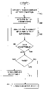
[0032] A flowchart for a method of qualifying turbocharger performance is
shown in
FIG. 4. A turbocharger is operated at a test condition at step 402. The
operation of
the turbocharger at this step may advantageously be performed using any method
suitable, for example, operation on an engine in a vehicle or connected to a
dynamometer, operation on a gas stand, or operation at an assembly line
station.
During operation of the turbocharger at the test condition, a set of
parameters is
acquired at step 404. These parameters, or data, may optionally include input
parameters to a system, such as air and/or fuel consumption of an engine,
energy
content or enthalpy of gas being supplied to the turbocharger by an engine or
a gas
stand, and so forth. Output parameters may also be measured, for example, an
energy content or enthalpy of an outlet gas of the turbocharger, a pressure
and/or
flow rate at an output of a compressor of the turbocharger, and so forth.
Other
variables may also be monitored, for example, if the turbocharger includes a
VNT, a
duty cycle that controls a vane position of the VNT may also be acquired.
[0033] The data acquired may be analyzed at step 406 against input and output
conditions of the turbocharger. The analysis may be performed by plotting data
points on a graph. The graph may include an input parameter on a horizontal
axis
versus one or more other input or output parameters on a vertical axis or
axes.
Each test condition may generate one or more points on the graph that
represent
input or output conditions. For example, if a turbocharger is being tested on
an
engine, as described above, the horizontal axis of the graph may represent a
fuel
consumption rate of the engine, and a vertical axis may represent both a
compressor outlet pressure and a VNT duty cycle. Points plotted for VNT duty
cycle
11
CA 02655517 2008-12-16
WO 2008/005679 PCT/US2007/071463
versus engine fuel consumption may represent an input condition for the
turbocharger, while a compressor outlet pressure versus fuel consumption may
represent an output condition.
[0034] Part of the analysis of the data at step 406 may include a
determination of
acceptability of the data at step 408, for example, by comparing at least one
input
parameter with a range of values that are specific to the test condition and
constitute
an acceptable range of inputs for the test. When the data acquired at step 404
is
deemed acceptable at step 408, a turbocharger is qualified and a pass or fail
determination is made at step 410. The qualification of the turbocharger at
step 410
is made by comparing at least one output value to an acceptable range of
output
values. If the output value of the turbocharger test falls within the
acceptable range,
the turbocharger is deemed to have passed the test successfully at step 412
otherwise, the turbocharger may be rejected at step 414 for having failed the
test.
[0035] Analytical methods for qualifying turbochargers may be applied, for
example,
in a manufacturing environment as a product quality monitoring measure.
Graphical
methods may be applied, for example, in a development environment. A flowchart
for an analytical application of a method of qualifying turbochargers,
arranged
specifically for turbocharger qualification in a manufacturing environment, is
shown
in FIG. 5. A turbocharger is received from an assembly process at step 502.
The
turbocharger may be a complete unit, or may alternatively be a partially built
unit that
is built with enough components to be functional but not finally assembled and
trimmed. The turbocharger may be attached to a test stand at step 504.
[0036] The test stand may include an electronic controller, or
microcontroller, that is
associated therewith, and appropriate hardware that is capable of retaining
the
turbocharger and sealing some or all of its fluid passages. The test stand may
also
be connected to an air, gas or another fluid pump that is arranged to generate
a flow
of fluid or air and route it to an inlet of the turbocharger turbine causing a
turbine
wheel to rotate at step 506. Various sensors may be associated with the test
stand
12
CA 02655517 2008-12-16
WO 2008/005679 PCT/US2007/071463
that are arranged to measure various parameters, for example, inlet and
pressure,
temperature, and/or flow rate of the turbine and compressor, shaft rotational
speed,
and so forth. These parameters may be acquired with sensors and relayed to an
electronic controller, at step 508. The electronic controller may analyze the
parameters and calculate turbocharger specific parameters, such as, turbine or
compressor efficiency.
[0037] Some of the parameters, for example compressor outlet pressure, may be
compared to acceptable value ranges at step 510, and a determination of
acceptability for the turbocharger may be made in the electronic controller at
step
512. A notification may be sent to a display or to another controller
associated with
the assembly process to either accept the turbocharger that has just been
tested, or
reject it and either scrap it or send it for rework based on the
determination, at step
514.
[0038] A block diagram of a test station 600, arranged and constructed to
qualify
turbocharger performance, is shown in FIG. 6. The test station 600 may include
a
fixture 602, an appropriate turbocharger mounting apparatus 604, an electronic
controller 606 associated therewith, and a fluid pump 608 that may be
connected to
an optional heater 610. A turbocharger 612 is shown connected to the test
station
600 for purposes of illustration. The turbocharger 612 has a turbine 614
having an
inlet passage 616 and an outlet passage 618, and a compressor 620 having an
inlet
passage 622 and an outlet passage 624. The configuration shown in FIG. 6 is
one
potential configuration of the test station 600 during testing of the
turbocharger 612.
[0039] For testing of the turbocharger 612, for example when the turbocharger
612
comes off an assembly line for end-of-line testing and/or quality control, the
turbocharger 612 may be connected to the test fixture 602 through the mounting
apparatus 604. The fluid pump 608 may be connected to the inlet passage 616 of
the turbine 614. The optional heater 610 may also be in fluid communication
with
the inlet passage 616 and connected between the turbine 614 and the fluid pump
13
CA 02655517 2008-12-16
WO 2008/005679 PCT/US2007/071463
608. The outlet passage 618 may be open to environment or vented to ambient.
The inlet passage 622 of the compressor 620 may be fluidly connected to a
source
of filtered air, and may contain a flow meter device 626. The outlet passage
624 of
the compressor 620 may be open to ambient, or may optionally be connected
(connection not shown) to a fluid or air inlet 632 of the fluid pump 608. The
outlet
passage 624 may also contain a flow orifice 628.
[0040] A work input, W, to activate and operate the fluid pump 606 may
initiate the
test after the turbocharger 612 has been connected to the test fixture 602.
The
pump 608 may supply a flow of air having a flow rate, m3, at a pressure, P5,
to the
inlet passage 616 to operate the turbine 614. The flow of air in the inlet
passage
616 may optionally be heated in the heater 610 that operates by a heat input,
Q.
The heater 610 may be an electric heater, or may alternatively be a gas-fired
heater
having a heat exchanger therein that is arranged to heat the air passing
therethrough. The turbine 614 may generate a work to operate the compressor
620
during the test by extracting energy from the air in the inlet passage 616,
and
exhaust the air from the passage 618 at a pressure, P6, which may be an
ambient
pressure or, alternatively, a vacuum in the case where optionally the outlet
passage
618 is connected to a source of vacuum or the inlet of the fluid pump 608.
[0041] The compressor 620, while operated by the turbine 614, may draw in a
flow
of air at a flow rate, m4, and a pressure, P7, through the inlet passage 622
thereof.
The flow rate m4 may be measured by the flow meter 626 and monitored during
the
test. The compressor 620 may compress the air from the pressure P7 to an
outlet
pressure, P8, present in the outlet passage 624 during the test. The flow
orifice 628
may advantageously be used in the outlet passage 624 to create a restriction
therein. The outlet pressure P7 may be an ambient pressure or, alternatively,
a
vacuum in the case where optionally the outlet passage 624 is connected to a
source of vacuum or the inlet of the fluid pump 608.
14
CA 02655517 2008-12-16
WO 2008/005679 PCT/US2007/071463
[0042] A reading from the flow meter 626, along with other readings of
pressure
sensors arranged to measure the pressures P5, P6, P7, and P8 may be
communicated to the electronic controller 606 for analysis, calculations,
and/or
processing. The results of the test of the turbocharger 612, along with a
determination of acceptability of the test or any other notifications may be
relayed
from the electronic controller to a display 630 that may notify an operator or
another
electronic device of any pertinent information about the turbocharger or the
test. For
example, a notification that the turbocharger 612 is acceptable and has passed
the
test may be relayed, a notification that the turbocharger 612 failed the test,
or a
notification to repeat the test, may be sent.
[0043] The test fixture 602 may be used to qualify an entire turbocharger
unit, or
individual components thereof. When, for example, qualification of the
performance
of the turbocharger 612 is desired, the mass flow m4 along with the pressures
P7
and P8 may be acquired, and plotted on a compressor map versus an energy input
to the turbine 614, or more advantageously, an enthalpy of the air in the
inlet
passage 616 that will depend on the work input W plus the heat input Q if the
heater
610 is used and active during the test. Typically, data for each turbocharger
tested
may be overlaid onto a turbine or compressor map and compared to a nominal, as
described above.
[0044] The embodiments described herein are advantageous in that a process is
provided for qualifying turbocharger units and components by testing the same
under fewer than before operating conditions, typically one or two, on either
an
engine or a gas stand. By using two data points, for example, assessment of
turbocharger performance at both low and high speed and load conditions are
represented. Results form these two data points may advantageously determine a
pass or fail determination for adequate turbocharger performance. Two data
points
appear to provide adequate information for a broad range of operation, but
narrower
operating range investigations may be adequately attained by a single data
point.
CA 02655517 2008-12-16
WO 2008/005679 PCT/US2007/071463
[0045] One advantage that may be realized by use of the embodiments described
herein is the ability to statistically qualify the performance of groups of
turbocharger
units, for example, turbocharger units belonging to a production run, or a
prototype
batch, and so forth. This statistical analysis may be used to diagnose groups
of
turbochargers, or even create parameters pertaining to the performance of
these
turbochargers for use as functional specifications.
[0046] A distribution curve of a group of turbochargers is shown in FIG. 7. A
group
of turbocharger units may be run at a single test condition, and an output
metric
value may be recorded. The information recorded for the group of turbocharger
units may be accumulated in the graph of FIG. 7, which represents a value for
the
output metric along a horizontal axis 702. A number or percentage of
turbocharger
units exhibiting performance within an increment of the scale of the
horizontal axis
702 is displayed on a vertical axis 704. A curve 706 may be created that may
show
the distribution of turbocharger performance. A peak point 708 of the curve
706 may
represent a nominal value 710 on the horizontal axis for the output metric.
Moreover, a maximum value 712 and a minimum value 714 may also be defined for
the output metric. The distribution shown in FIG. 7 has a shape of a normal
distribution, but other distributions may also arise. The maximum limit 712
and
minimum limit 714 may be subsequently used to either define acceptance
criteria of
turbochargers not belonging to the group of turbocharger units tested.
[0047] The present invention may be embodied in other specific forms without
departing from its spirit or essential characteristics. The described
embodiments are
to be considered in all respects only as illustrative and not restrictive. The
scope of
the invention is, therefore, indicated by the appended claims rather than by
the
foregoing description. All changes that come within the meaning and range of
equivalency of the claims are to be embraced within their scope.
What is claimed is:
16