Note: Descriptions are shown in the official language in which they were submitted.
CA 02655703 2009-02-26
Hygienic Coupling and Fitting Seal System
BACKGROUND OF THE INVENTION
The present invention relates to a seal system and, more particularly, to a
hygienic coupling and fitting seal system for pharmaceutical, dairy, beverage,
or other
sanitary industries.
Various seals have been widely utilized in various industries. The seals
utilized
in plants or factories processing pharmaceutical, beverage, dairy products, or
the like
should be taken apart for periodic cleaning and should be made of a material
capable of
withstanding the processing. However, "binding", "rippling up", and intrusion
commonly occurred on conventional seals, including but not limited to flat
gaskets,
O-rings, and other industry standard gaskets, creating potential for loosing
the sealing
effect and for becoming a hygienic issue. For agitator couplings, conventional
O-rings
that are exposed and flush or slightly protrude do not always remain engaged
and can
actually loose the sealing effect and fall out.
Thus, a need exists for a hygienic coupling and fitting seal system that is
easy to
clean while providing reliable sealing effect.
BRIEF SUMMARY OF THE INVENTION
The present invention solves this need and other problems in the field of
hygienic coupling and fitting seals by providing, in a preferred form, a seal
system
including a tail having an annular first surface and an annular second surface
parallel to
and spaced from the annular first surface in a first direction. The tail has a
first thickness
between the annular first and second surfaces in the first direction. The tail
further
includes first and second peripheral edges extending between and adjoining the
annular
first and second surfaces. The first and second peripheral edges are spaced
from each
other in a second direction perpendicular to the first direction. A first
annular ring
1
CA 02655703 2009-02-26
integrally extends from a portion of the tail for a first extent from the
first peripheral edge
towards but spaced from the second peripheral edge of the tail. The first
annular ring and
the portion of the tail form a seal. The seal includes an exterior including
the first
peripheral edge. The exterior of the seal has a second thickness parallel to
the first
thickness. The second thickness of the seal continuously increases and then
continuously
decreases from the first peripheral edge towards the second peripheral edge of
the tail.
The exterior of the seal is free of protrusions.
In preferred forms, the first annular ring integrally extends from the annular
first
surface, and the exterior of the seal includes the annular second surface for
the first
extent from the first peripheral edge towards but spaced from the second
peripheral edge.
The seal has generally semicircular cross sections in a plane including the
first and
second directions. In alternate preferred forms, the first annular ring
integrally extends
from the annular first and second surfaces, and the seal has generally
circular cross
sections in the plane including the first and second directions.
In a preferred form, a second annular ring integrally extends from another
portion of the tail for a second extent from the second peripheral edge
towards but
spaced from the first peripheral edge. The second annular ring and the other
portion of
the tail form a seal element. The seal element includes an exterior including
the second
peripheral edge. The exterior of the seal element has a third thickness
parallel to the first
thickness. The third thickness of the seal element continuously increases and
then
continuously decreases from the second peripheral edge towards the first
peripheral edge.
The exterior of the seal element is free of protrusions.
In preferred forms, the annular first and second surfaces are L-shaped and
include first and second sections extending generally perpendicularly to each
other. The
first thickness of the first section is perpendicular to the first thickness
of the second
section.
2
CA 02655703 2009-02-26
The present invention will become clearer in light of the following detailed
description of illustrative embodiments of this invention described in
connection with
the drawings.
DESCRIPTION OF THE DRAWINGS
The illustrative embodiments may best be described by reference to the
accompanying drawings where:
Figure 1 shows a plan view of a hygienic coupling and fitting seal system
according to the preferred teachings of the present invention.
Figure 2 shows a cross sectional view of the seal system of Figure 1 according
to section line 2-2 of Figure 1.
Figure 3 shows a partial, cross sectional view of the seal system of Figure 1
in
use as a hygienic coupling.
Figure 4 shows a cross sectional view illustrating use of a seal system of
Figure
9B in a standard fitting.
Figure 5 shows a cross sectional view illustrating use of the seal system of
Figure 9A and the seal system of Figure 9B in a tube or pipe coupling.
Figure 6 shows a cross sectional view illustrating use of the seal system of
Figure 9A in a multiple impeller shaft coupling assembly.
Figure 7 shows a cross sectional view illustrating use of the seal system of
Figure 9A in a removable agitator blade design.
Figure 8 shows a cross sectional view illustrating use of the seal system of
Figure 9B in a sanitary fitting connection between a blind threaded port or
tank fitting
and a screw cap fitting.
Figure 9A-9F show cross sectional views of various embodiments of the
hygienic coupling and fitting seal system according to the preferred teachings
of the
present invention.
3
CA 02655703 2009-02-26
Figure 10 shows a cross sectional view illustrating use of the seal system of
Figure 9C in a flange seal.
Figure 11 shows a cross sectional view illustrating use of the seal system of
Figure 9A and the seal system of Figure 9D in an agitator bottom bearing seal
in a
mount.
Figure 12 shows a cross sectional view illustrating use of the seal system of
Figure 9D in a bolt application.
Figure 13 shows a plan view of a further embodiment of the seal system
according to the preferred teachings of the present invention allowing to mate
with
conventional sou systems.
Figure 14 shows a cross sectional view of the seal system of Figure 13
according to section line 14-14 of Figure 13.
Figure 15A-15L shows further embodiments of the seal system according to the
preferred teachings of the present invention.
Figure 16 shows a cross sectional view illustrating use of the seal system of
Figure 9B and the seal system of Figure 15A in an agitator bottom bearing seal
in a
mount.
Figure 17 shows a cross sectional view illustrating use of the seal system of
Figure 15K in a sanitary fitting connection between a blind threaded port or
tank fitting
and a screwed pipe/tube fitting.
Figure 18 shows a cross sectional view illustrating use of the seal system of
Figure 9A and the seal system of Figure 15B in a stacked hub assembly for an
agitator
shaft with removable hub and blade assemblies and retaining nut with torque
alignment
pins.
All figures are drawn for ease of explanation of the basic teachings of the
present invention only; the extensions of the figures with respect to number,
position,
4
CA 02655703 2009-02-26
relationship, and dimensions of the parts to form the preferred embodiments
will be
explained or will be within the skill of the art after the following teachings
of the present
invention have been read and understood. Further, the exact dimensions and
dimensional
proportions to conform to specific force, weight, strength, and similar
requirements will
likewise be within the skill of the art after the following teachings of the
present
invention have been read and understood.
Where used in the various figures of the drawings, the same numerals designate
the same or similar parts. Furthermore, when the terms "first", "second",
"third",
"upper", "lower", "inner", "outer", "end", "portion", "section", "axial",
"radial",
"circumferential", "annular", "spacing", "length", "thickness", and similar
terms are
used herein, it should be understood that these terms have reference only to
the structure
shown in the drawings as it would appear to a person viewing the drawings and
are
utilized only to facilitate describing the invention.
DETAILED DESCRIPTION OF THE INVENTION
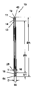
A hygienic coupling and fitting seal system according to the preferred
teachings
of the present invention is shown in the drawings and generally designated 10.
According to the teachings of the present invention, seal system 10 includes a
tail 14
having an annular first surface 16 and an annular second surface 18 which in
the
preferred forms shown is parallel to and spaced from annular first surface 16
in a first
direction. Tail 14 has a first thickness T between annular first and second
surfaces 16 and
18 in the first direction. Tail 14 further includes first and second
peripheral edges 22 and
28 extending between and adjoining annular first and second surfaces 16 and
18. First
and second peripheral edges 22 and 28 are spaced from each other in a second
direction
perpendicular to the first direction. In the preferred forms shown, tail 14
has generally
rectangular cross sections in a plane including the first and second
directions.
5
CA 02655703 2009-02-26
According to the teachings of the present invention, a first annular ring 40
integrally extends from a portion of tail 14 for a first extent El from first
peripheral edge
22 towards but spaced from second peripheral edge 28 of tail 14. First annular
ring 40
and the portion of tail 14 form a seal 54 having an exterior including first
peripheral edge
22. The exterior of seal 54 has a second thickness D parallel to first
thickness T. Second
thickness D of seal 54 continuously increases and then continuously decreases
from first
peripheral edge 22 towards second peripheral edge 28 of tail 14. In a
preferred
embodiment shown in Figure 2, seal system 10 is formed of two components 11
and 13.
Component 11 includes the exterior of seal 54 and a groove receiving component
13. Tail
14 is formed of component 13 and a portion of component 11 aligned with
component 13
in the second direction.
In a preferred form shown in Figures 2 and 9A, annular first and second
surfaces
16 and 18 extend in a radial direction and are spaced in an axial direction
perpendicular
to the radial direction. Furthermore, first peripheral edge 22 is an outer
peripheral edge of
tail 14, and second peripheral edge 28 is an inner peripheral edge of tail 14
spaced from
the outer peripheral edge in the second direction which is the radial
direction, with the
inner peripheral edge radially inward of the outer peripheral edge. First
annular ring 40
integrally extends from annular first and second surfaces 16 and 18.
Furthermore, in the
form shown, seal 54 has generally circular cross sections in the plane
including the first
and second directions and is in the form of an O-ring 12, with first extent El
equal to the
maximum second thickness D.
In a preferred form shown in Figure 9B, annular first and second surfaces 16
and
18 extend in a radial direction and are spaced in an axial direction
perpendicular to the
radial direction. Furthermore, first peripheral edge 22 is the inner
peripheral edge of tail
14, and second peripheral edge 28 is the outer peripheral edge of tail 14
spaced from the
inner peripheral edge in the second direction which is the radial direction,
with the inner
6
CA 02655703 2009-02-26
peripheral edge radially inward of the outer peripheral edge. First annular
ring 40
integrally extends from annular first and second surfaces 16 and 18.
Furthermore, in the
form shown, seal 54 has generally circular cross sections in the plane
including the first
and second directions and is in the form of an O-ring 12, with first extent El
equal to the
maximum second thickness D.
In a preferred form shown in Figure 9C, annular first and second surfaces 16
and
18 extend in a radial direction and are spaced in an axial direction
perpendicular to the
radial direction. Furthermore, first peripheral edge 22 is the inner
peripheral edge of tail
14, and second peripheral edge 28 is the outer peripheral edge of tail 14
spaced from the
inner peripheral edge in the second direction which is the radial direction,
with the inner
peripheral edge radially inward of the outer peripheral edge. First annular
ring 40
integrally extends from annular first surface 16, and the exterior of seal 54
includes
annular second surface 18 for first extent El from first peripheral edge 22 of
tail 14
towards but spaced from second peripheral edge 28 of tail 14. Furthermore, in
the form
shown, seal 54 has generally semicircular cross sections 58 in the plane
including the first
and second directions.
In a preferred form shown in Figure 9D, annular first and second surfaces 16
and
18 extend in a radial direction and are spaced in an axial direction
perpendicular to the
radial direction. Furthermore, first peripheral edge 22 is the outer
peripheral edge of tail
14, and second peripheral edge 28 is the inner peripheral edge of tail 14
spaced from the
outer peripheral edge in the second direction which is the radial direction,
with the inner
peripheral edge radially inward of the outer peripheral edge. First annular
ring 40
integrally extends from annular first surface 16, and the exterior of seal 54
includes
annular second surface 18 for first extent El from first peripheral edge 22 of
tail 14
towards but spaced from second peripheral edge 28 of tail 14. Furthermore, in
the form
7
CA 02655703 2009-02-26
shown, seal 54 has generally semicircular cross sections 58 in the plane
including the first
and second directions.
According to further preferred forms according to the teachings of the present
invention, a second annular ring 50 integrally extends from the other portion
of tail 14 for
a second extent E2 from second peripheral edge 28 towards but spaced from
first
peripheral edge 22. Second annular ring 50 and the other portion of tail 14
form a seal
element 56 having an exterior including second peripheral edge 28. The
exterior of seal
element 56 has a third thickness T3 parallel to first thickness T. Third
thickness T3 of seal
element 56 continuously increases and then continuously decreases from second
peripheral edge 28 towards first peripheral edge 22.
In a preferred form shown in Figure 9E, annular first and second surfaces 16
and
18 extend in a radial direction and are spaced in an axial direction
perpendicular to the
radial direction. Furthermore, first annular ring 40 integrally extends from
annular first
and second surfaces 16 and 18. Second annular ring 50 integrally extends from
annular
first and second surfaces 16 and 18. Furthermore, each of seal 54 and seal
element 56 has
generally circular cross sections in the plane including the first and second
directions and
in the form of an O-ring 12. Further, in the form shown, seal element 56 is of
a size
substantially equal to seal 54, and the maximum third thickness T3 is equal to
first extent
El, second extent E2, and the maximum second thickness D and larger than first
thickness T of tail 14.
In a preferred form shown in Figure 9F, annular first and second surfaces 16
and
18 extend in a radial direction and are spaced in an axial direction
perpendicular to the
radial direction. Furthermore, first annular ring 40 integrally extends from
annular first
surface 16, and the exterior of seal 54 includes annular second surface 18 for
first extent
El from first peripheral edge 22 of tail 14 towards but spaced from second
peripheral
edge 28 of tail 14. Second annular ring 50 integrally extends from annular
first surface 16,
8
CA 02655703 2009-02-26
and the exterior of seal element 56 includes annular second surface 18 for
second extent
E2 from second peripheral edge 28 of tail 14 towards but spaced from first
peripheral
edge 22 of tail 14. Furthermore, in the form shown, each of seal 54 and seal
element 56
has generally semicircular cross sections 58 in the plane including the first
and second
directions. Furthermore, seal element 56 is of a size equal to seal 54, and
the maximum
third thickness T3 is equal to the maximum second thickness D which is larger
than first
thickness T of tail 14.
In preferred forms shown in Figures 15A-15D, first annular ring 40 integrally
extends from annular first and second surfaces 16 and 18, and the exterior of
seal element
56 includes one of annular first and second surfaces 16 and 18 for second
extent E2, with
seal element 56 being of a size smaller than seal 54. Specifically, in the
forms shown, seal
54 has generally circular cross sections in the plane including the first and
second
directions, with first extent El of seal 54 generally more than two times of
second extent
E2 of seal element 56. Particularly, in the preferred form shown in Figure
15A, annular
first and second surfaces 16 and 18 extend in an axial direction and are
spaced in a radial
direction perpendicular to the axial direction. Furthermore, tail 14 is in the
form of a
hollow cylinder, and second annular ring 50 integrally extends from annular
second
surface 18 that is an inner cylindrical surface of the hollow cylinder.
Furthermore, seal 54
and seal element 56 are spaced in the second direction which is the axial
direction. In the
preferred form shown in Figure 15B, annular first and second surfaces 16 and
18 extend
in an axial direction and are spaced in a radial direction perpendicular to
the axial
direction. Furthermore, tail 14 is in the form of a hollow cylinder, and
second annular
ring 50 integrally extends from annular first surface 16 that is an outer
cylindrical surface
of the hollow cylinder. Furthermore, seal 54 and seal element 56 are spaced in
the second
direction which is the axial direction. In the preferred form shown in Figure
15C, annular
first and second surfaces 16 and 18 extend in a radial direction and are
spaced in an axial
9
CA 02655703 2009-02-26
direction perpendicular to the radial direction. Furthermore, second annular
ring 50
integrally extends from annular first surface 16, and seal 54 and seal element
56 are
spaced in the second direction which is the radial direction, with seal 54
radially outward
of seal element 56. In the preferred form shown in Figure 15D, annular first
and second
surfaces 16 and 18 extend in a radial direction and are spaced in an axial
direction
perpendicular to the radial direction. Furthermore, second annular ring 50
integrally
extends from annular first surface 16, and seal 54 and seal element 56 are
spaced in the
second direction which is the radial direction, with seal element 56 radially
outward of
seal 54.
In preferred forms shown in Figures 15E-15H, tail 14 is in the form of a
hollow
cylinder, first annular ring 40 integrally extends from annular first surface
16, and the
exterior of seal 54 includes annular second surface 18 for first extent El
from first
peripheral edge 22 towards but spaced from second peripheral edge 28.
Furthermore, the
exterior of seal element 56 includes one of annular first and second surfaces
16 and 18 for
second extent E2, with seal element 56 being of a size smaller than seal 54.
Specifically,
in the forms shown, seal 54 has generally semicircular cross sections 58 in
the plane
including the first and second directions, with first extent El of seal 54
generally more
than two times of second extent E2 of seal element 56. Furthermore, annular
first and
second surfaces 16 and 18 are spaced in the first direction which is a radial
direction, and
first and second peripheral edges 22 and 28 are spaced in the second direction
which is an
axial direction perpendicular to the radial direction. Further, seal 54 seal
element 56 are
spaced in the second direction which is the axial direction. Particularly, in
the preferred
form shown in Figure 15E, both first and second annular rings 40 and 50
integrally
extend from annular first surface 16 that is an outer cylindrical surface of
the hollow
cylinder. In the preferred form shown in Figure 15F, first annular ring 40
integrally
extend from annular first surface 16 that is an inner cylindrical surface of
the hollow
CA 02655703 2009-02-26
cylinder, and second annular ring 50 integrally extends from annular second
surface 18
that is the outer cylindrical surface of the hollow cylinder. In the preferred
form shown in
Figure 15Q both first and second annular rings 40 and 50 integrally extend
from annular
first surface 16 that is the inner cylindrical surface of the hollow cylinder.
In the preferred
form shown in Figure 15H, first annular ring 40 integrally extends from
annular first
surface 16 that is the outer cylindrical surface of the hollow cylinder, and
second annular
ring 50 integrally extends from annular second surface 18 that is the inner
cylindrical
surface of the hollow cylinder.
In preferred forms shown in Figures 151-15L, tail 14 is L-shaped.
Specifically,
annular first and second surfaces 16 and 18 are L-shaped and include first and
second
sections 62 and 64 extending generally perpendicular to each other. First
thickness T of
first section 62 is perpendicular to first thickness T of second section 64.
Furthermore,
second section 64 is in the form of a hollow cylinder, and first section 62 is
in the form of
a radially extending flange. First annular ring 40 integrally extends from
annular first
surface 16, and the exterior of seal 54 includes annular second surface 18 for
first extent
El from first peripheral edge 22 towards but spaced from second peripheral
edge 28.
Furthermore, the exterior of seal element 56 includes one of annular first and
second
surfaces 16 and 18 for second extent E2, with seal element 56 being of a size
smaller than
seal 54. Specifically, in the forms shown, seal 54 has generally semicircular
cross
sections 58 in the plane including the first and second directions, with first
extent El of
seal 54 generally more than two times of second extent E2 of seal element 56.
Particularly, in the preferred form shown in Figure 151, first annular ring 40
integrally extends from annular first surface 16 of first section 62 extending
radially
outwardly of second section 64, with annular first surface 16 of second
section 64 being a
radially outer surface of the hollow cylinder forming second section 64.
Furthermore,
second annular ring 50 integrally extends from annular first surface 16 of
second section
11
CA 02655703 2009-02-26
64. In the preferred form shown in Figure 15J, first annular ring 40
integrally extends
from annular first surface 16 of first section 62 extending radially outwardly
of second
section 64, with annular first surface 16 of second section 64 being a
radially inner
surface of the hollow cylinder forming second section 64. Furthermore, second
annular
ring 50 integrally extends from annular second surface 18 of second section
64. In the
preferred form shown in Figure 15K, first annular ring 40 integrally extends
from annular
first surface 16 of first section 62 extending radially inward of second
section 64, with
annular first surface 16 of second section 64 being the radially inner surface
of the hollow
cylinder forming second section 64. Furthermore, second annular ring 50
integrally
extends from annular first surface 16 of second section 64. In the preferred
form shown in
Figure 15L, first annular ring 40 integrally extends from annular first
surface 16 of first
section 62 extending radially inward of second section 64, with annular first
surface 16 of
second section 64 being a radially outer surface of the hollow cylinder
forming second
section 64. Furthermore, second annular ring 50 integrally extends from
annular second
surface 18 of second section 64.
According to the teachings of the present invention, seal system 10 is formed
from sealable/compression control type materials and in the most preferred
form is
Telfon based. However, other thermoplastics (TP) or thermoplastic elastomers
(TPEs)
type materials can be used.
In a preferred form shown in Figures 13 and 14, annular first and second
surfaces 16 and 18 extend radially. Seal system 10 includes seal 54 in the
most preferred
form shown as a half O-ring 102 formed on annular first surface 16 of tail 14,
seal
element 56 in the most preferred form shown as a half O-ring 104 formed on
annular
second surface 18 of tail 14, and a tail extension 106. Seal 54 and seal
element 56 are
radially spaced from and oppose each other, with seal element 56 located
radially
outward of seal 54. Seal element 56 includes an annular groove 23 in second
peripheral
12
CA 02655703 2009-02-26
edge 28, and tail extension 106 includes a ledge 108 engaged in annular groove
23. Tail
extension 106 may be separately formed and in the most preferred form of
different
materials than tail 14, seal 54, and seal element 56 such as of non-
compressible material.
Seal 54 is of a larger radius than seal element 56, with seal 54 having a
radius of 0.70
inches (1.78 cm) and with seal element 56 having a radius of 0.46 inches (1.17
cm) in
the most preferred form shown. Seal system 10 is advantageous in that one side
of it can
adopt a conventional seal installation. As an example, seal system 10 can mate
with
current industry sou systems. Other similar adaptations to existing seals can
be made
according to the teachings of the present invention.
Now that the basic construction of the seal systems 10 of the preferred
teachings
of the present invention has been explained, the operation and some of the
advantages of
seal systems 10 can be set forth and appreciated. In an application of seal
systems 10 of
Figures 1, 2, 9A, and 9B between first and second fitting members 70 and 80
shown in
Figure 3, seal system 10 is generally mounted between an end face 72 of first
fitting
member 70 and an end face 82 of second fitting member 80 to form a sealing
assembly.
First and second fitting members 70 and 80 are mounted in an environment
containing
and/or allowing passage of a product such as a fluid and extend in the first
direction.
First and second fitting members 70 and 80 include a product contact side 86
in contact
with the product. End face 72 of first fitting member 70 extends in the second
direction
and includes an annular groove 20 adjoining product contact side 86. Annular
groove 20
is of a size equal to a portion of first annular ring 40 extending from
annular first surface
16 away from annular second surface 18. In the preferred forms shown, end face
82 of
second fitting member 80 extends in the second direction and includes an
annular groove
21 facing annular groove 20. Annular groove 21 has a size equal to another
portion of
first annular ring 40 extending from annular second surface 18 away from
annular first
surface 16. Annular groove 20 has a diameter which is the same as that of
annular
13
CA 02655703 2009-02-26
groove 21. An annular gap 74 is defined between end faces 72 and 82 and in
communication with annular grooves 20 and 21. Annular gap 74 has a depth D1 in
the
first direction equal to first thickness T of tail 14. Seal 54 in the form of
O-ring 12 is
received in annular grooves 20 and 21 and adjacent product contact side 86,
and tail 14
is received in annular gap 74. Thus, seal 54 is exposed on product contact
side 86
between end faces 72 and 82 generally equal to depth DI.
Seal systems 10 according to the preferred teachings of the present invention
can have various applications and can be utilized in various combinations.
Figure 4
shows use of seal system 10 of Figure 9B between first and second fitting
members 70
and 80 in the preferred form shown as two pipes, with product contact side 86
inside of
the two pipes. Figure 5 shows use of a combination of seal system 10 of Figure
9A and
seal system 10 of Figure 9B in a tube or pipe coupling of a conduit including
first and
second fitting members 70 and 80. The conduit passes through a tank or the
like
containing fluid, with the fluid on inside and outside of the conduit. Figure
6 shows use
of seal system 10 of Figure 9A in a multiple impeller shaft coupling assembly
including
a plurality of shafts 94 for operation in fluid, such shafts 94 including
blades for
agitating the fluid located outside of shafts 94. Figure 7 shows use of seal
system 10 of
Figure 9A in a removable agitator blade design between a blade impeller 90 and
a blade
92. Figure 8 shows use of seal system 10 of Figure 9A in a sanitary fitting
connection
between first fitting member 70 in the preferred form shown as a blinded
threaded port
or tank fitting 24 and second fitting member 80 in the preferred form shown as
a screw
cap fitting 26. Figure 10 shows use of seal system 10 of Figure 9C in a flange
seal
between first and second fitting members 70 and 80. Figure 11 shows use of
seal system
10 of Figure 9A and seal system 10 of Figure 9D in an agitator bottom bearing
seal in a
mount 30 including first and second fitting members 70 and 80. Figure 12 shows
use of
seal system 10 of Figure 9D in a bolt application. An optional agitator
coupling `stop'
14
CA 02655703 2009-02-26
bolt utilizing seal system 10 of the present invention guarantees no backing
out during
operation. This bolt seal design can also be used for other bolting
applications having
product contact such as pump impeller retaining bolts.
Likewise, Figure 16 shows use of a combination of seal system 10 of Figure 9B
and the seal system of Figure 15A in an agitator bottom bearing seal in a
mount 30
including first and second fitting members 70 and 80. For seal system 10 of
Figure 15A,
first fitting member 70 includes an annular recess 84 extending
perpendicularly to and in
communication with annular gap 74. Annular recess 84 has a spacing to product
contact
side 86 larger than annular groove 20. In this application, seal element 56
having a size
smaller than seal 54 acts as a retaining lip, and seal system 10 with seal
element 56 is
compressed by the ID/OD fit of mount 30, unlike the normal compression method.
Specific tolerances are applied for the correct compression. In its most
preferred form of
Teflon or thermoplastic, installation while screwing or rotating is easy due
to the
self-lubricating seal system 10 and non-binding of seal 54 in the form of O-
ring 12. In
this application, the seal is static but is sealed in the rotational
direction.
Furthermore, Figure 17 shows use of seal system 10 of Figure 15K in a sanitary
fitting connection between first fitting member 70 in the preferred form shown
as a blind
threaded port or tank fitting 32 and second fitting member 80 in the preferred
form
shown as a screwed pipe/tube fitting 33. It can be appreciated that first
fitting member 70
includes an L-shaped annular gap 74 including first and second portions
extending
generally perpendicularly to each other. Furthermore, first fitting member 70
includes an
annular recess 84 extending perpendicularly to and in communication with the
second
portion of annular gap 74. Annular recess 84 has a spacing to product contact
side 86
larger than annular groove 20. L-shaped tail 14 is received in L-shaped
annular gap 74,
and seal element 56 of a size smaller than seal 54 and acting as a retaining
lip is received
in annular recess 84.
CA 02655703 2009-02-26
Further, Figure 18 shows use of a combination of seal system 10 of Figure 9A
and seal system 10 of Figure 15B in a stacked hub assembly for an agitator
shaft 38 with
removable impeller blade and hub assemblies 34 and 35 and a retaining nut 36
with
torque alignment pins 37. This application allows agitator impeller blade and
hub
assemblies 34 and 35 to be installed and removed on agitator shaft 38 while
maintaining
hygienic sealing effect. Similar to Figure 16, seal system 10 with seal
element 56 of a
size smaller than seal 54 and acting as a retaining lip is compressed by the
ID/OD fit of
retaining nut 36 and agitator shaft 38 in Figure 18. Unlike the normal
compression
method, in addition an angle A, ranging from 0 - 3 degrees, preferable 1
degree,
produces a taper to allow a loose fit during initial assembly but ensures the
correct
compression when assembled completely. Specific tolerances are applied for the
correct
compression. This angle and compression method can also be applied to Figure
16
according to the teachings of the present invention.
Seal systems 10 according to the preferred teachings of the present invention
allow a flush seal surface and cleanability in product contact side 86.
Specifically,
conventional flat gaskets can `extrude' or create `overhang' which creates
cleaning
problems. In the application of seal system 10 having seal 54 in the form of O-
ring 12
utilized in first and second fitting members 70 and 80 having annular grooves
20 and 21,
seal 54 is free of protrusions and exposed on product contact side 86 through
a gap
between end faces 72 and 82 generally equal to depth D1. Thus, tail 14 and
dual side
annular grooves 20 and 21 of the seal system according to the teachings of the
present
invention allow seal 54 to be compressed without being "extruded" and allow
easy
installation. Seal 54 is allowed to be "pushed out flush" into product contact
areas, so
that "flat" areas on the product contact side in conventional O-rings that can
be more
difficult to clean is eliminated in seal systems 10 according to the preferred
teachings of
the present invention. Smooth profile on the inner or outer diameter of seal
54 and
16
CA 02655703 2009-02-26
annular grooves 20 and 21 eliminate gasket `extrusion' and allows better
cleanability.
However, seal 54 can be compressed to a designated amount, such as but not
limited to
0.020 inches (0.05 cm) in the preferred form, so extrusion is limited and
remains
smooth/round. It can be appreciated that dual sided annular grooves 20 and 21
allow
even compression on both sides, which is advantageous over conventional O-ring
methods usually employing one-sided machining only. When utilized in agitator
couplings, seal 54 remains engaged, unlike conventional O-rings that remain
engaged
but normally have crevices that can be more difficult to clean.
Seal systems 10 according to the teachings of the present invention including
seal 54 and seal element 56 in the form of O-ring 12 and/or semicircular cross
sections
also provide better cleanability in product contact side 86, because seal 54
and seal
element 56 are free of protrusions and are exposed on product contact side 86.
Furthermore, seal 54 and seal element 56 have smooth profiles and do not
protrude into
product contact side 86 so that are no flat areas.
Furthermore, conventional O-ring methods usually require holding a gasket in
place until almost tight. Seal systems 10 according to the preferred teachings
of the
present invention are self-centering for ease of installation. Furthermore,
seal element 56
of a size smaller than seal 54 and acting as a retaining lip can hold seal
system 10 to
allow installation without holding seal systems 10 in place, eliminating the
possibility of
pinching fingers. Specifically, seal element 56 acting as a retaining lip
helps retain seal
system 10 during assembly. Seal element 56 acting as a retaining lip is
designed to allow
easy assembly, especially in blind applications as shown in Figure 17.
Furthermore, seal systems 10 according to the preferred teachings of the
present
invention can be tightened/secured without the `binding and rippling up' which
commonly occurs on conventional flat gaskets, O-rings, and other industry
standard
gaskets and which creates potential for loosing the sealing effect and becomes
a cleaning
17
CA 02655703 2009-02-26
issue. Due to self-lubricating in its most preferred form of Teflon or
thermoplastic, seal
systems 10 of the present invention allow circumferential direction while
achieving a
tight compressive sealing effect.
Now that the basic teachings of the present invention have been explained,
many extensions and variations will be obvious to one having ordinary skill in
the art.
For example, although seal 54 and seal element 56 are shown as being of
circular or
semicircular cross sections, seal 54 and seal element 56 can have other shapes
according
to the preferred teachings of the present invention including ellipsoidal,
race tank shaped,
or the like. Further, seal systems 10 according to the preferred teachings of
the present
invention can be utilized in combination other than those shown.
Thus since the invention disclosed herein may be embodied in other specific
forms without departing from the spirit or general characteristics thereof,
some of which
forms have been indicated, the embodiments described herein are to be
considered in all
respects illustrative and not restrictive. The scope of the invention is to be
indicated by
the appended claims, rather than by the foregoing description, and all changes
which
come within the meaning and range of equivalency of the claims are intended to
be
embraced therein.
18