Note: Descriptions are shown in the official language in which they were submitted.
ak 02656051 2013-11-01
1
Apparatus for labelling.
The invention relates to an apparatus and a method for
labelling containers, in particular for making and
subsequently applying to containers sleeve or "shrink
sleeve" labels in PET, PVC, polypropylene (PP), polystyrene
(PS), or other materials suitable for being heat shrunk.
The term "shrink sleeve" is taken to mean tubular labels
made of film made of plastics that are placed on a container
and are subsequently heated to shrink onto the external
W surface of the container and take the shape thereof.
In known labelling apparatuses, the "shrink sleeve" labels
are obtained from a film made of shrinkable plastics that is
unwound from a reel and is advanced by a moving device to a
transferring drum.
A cutting device cuts the film made of plastics transversely
to the advancing direction, in such a way as to obtain
portions of film made of plastics having a preset length,
measured longitudinally to the film made of plastics, so as
to obtain "shrink sleeve" labels having a preset diameter.
The cut portions are wound onto consecutive zones of a
transferring drum and are maintained adhering to the
external surface thereof.
The transferring drum is adjacent to a rotatable carousel
that rotatably supports a plurality of spindles peripherally
and angularly equidistant from one another, with each
spindle there being associated a support shaped for
supportingly receiving a container to be labelled.
Each spindle is shaped for receiving from the transferring
drum a portion of film made of plastics from which a sleeve
is obtained that is a precursor of a "shrink sleeve" label.
The portions of film made of plastics can be welded by one
or more external welding means, that are generally fixed
with respect to the base of the machine or by one or more
welding means associated with each spindle.
The welding means may, for example, be ultrasound, hot-
roller, or hot-air welding means.
CA 02656051 2008-12-22
WO 2007/148189
PCT/1B2007/001613
2
In the aforesaid labelling machines the portions of film
made of plastics may form creases whilst they are wound on
the respective spindles.
Further, in such machines it is desirable to maintain the
end flaps of each portion overlapping and mutually adhering,
the portion being wound around a respective spindle so as to
promote the welding thereof.
An object of the invention is to improve the apparatuses and
methods for obtaining "shrink sleeve" labels for containers.
Another object of the invention is to obtain an apparatus
and a method that enable the label portions to be arranged
in an extended manner and without creases on the external
surface of the respective spindles.
In a first aspect of the invention, there is provided an
apparatus for making "shrink sleeve" labels, comprising a
carousel provided peripherally with spindle means shaped for
being wound by portions of film made of plastics, a
transferring unit arranged peripherally to said carousel for
transferring each portion of film made of plastics to a
respective spindle, characterised in that there is provided
electrostatic-charge generating means downstream of said
transferring unit such as to charge electrostatically said
portions of film made of plastics.
In a second aspect of the invention, there is provided a
method for labelling containers, comprising forming a sleeve
and covering a container with said sleeve, said forming
comprising winding a portion of film made of plastics on a
respective spindle and maintaining said portion of film made
of plastics adhering to said spindle in an electrostatic
manner.
Owing to the fact that the portions of film are treated
electrostatically they are evenly extended on the surface of
the respective spindles and are free of creases.
Further, the flaps opposite each portion of film are
maintained adhering to one another through the effect of the
CA 02656051 2008-12-22
WO 2007/148189
PCT/1B2007/001613
3
electrostatic charges and can thus be welded simply and
without defects.
There can be provided welding means of the flaps of the
portions of film of known type such as to act by pressing
together the flaps opposite each portion, or such as to
cause welding without coming into contact with the flaps
(for example laser welding).
The opposite flaps of each portion of film made of plastics
can be joined together with systems other than welding, for
example through gluing.
Further, if the effect of temporary adhesion of the portions
of film made of plastics to the respective spindles is
sufficient, it is possible to provide spindles devoid of the
air suction system that is normally provided for maintaining
the portions of film made of plastics adhering temporarily
to the spindles.
The invention can be better understood and implemented with
reference to the attached drawings, which show an embodiment
thereof by way of non-limiting example, in which:
Figure 1 is a schematic view from above of an apparatus for
labelling containers according to the invention;
Figure 2 is an enlarged schematic view of a portion of the
apparatus in Figure 1;
Figure 3 is a schematic view of an apparatus for labelling
containers where welding is achieved by one or more external
welding means, for example laser welding means without
contact.
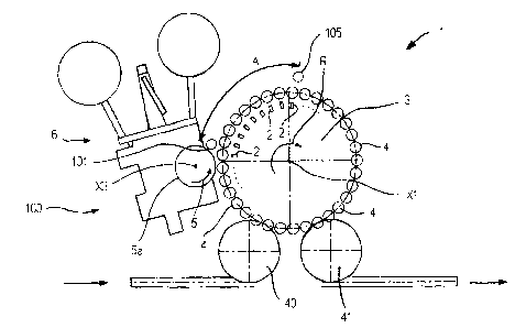
With reference to Figure 1, an apparatus 1 for labelling
containers (not shown), comprises a carousel 3, which is
rotatable around a first rotation axis x1, in a first
rotation direction R.
The carousel 3 peripherally supports spindle means 4 on
which sleeves 11 are formed that are the precursors of
"shrink sleeve" labels.
The spindle means comprises a plurality of spindles 4 that
are distributed angularly equidistant on the periphery of
CA 02656051 2008-12-22
WO 2007/148189
PCT/1B2007/001613
4
the carousel 3, and is rotatable, in a respective rotation
direction Q corresponding to the first rotation direction R,
around respective second axes X2 arranged substantially
parallel to the first rotation axis X1.
The apparatus 1 comprises a moving device 6 that moves along
an advancing path a film made of heat shrinkable plastics
that is removed from a reel on which it is initially wound.
With the moving device 6 there is associated cutting means,
arranged for cutting the film made of plastics transversely
to the advancing path, so as to obtain portions of film made
of plastics 8 (Figure 2), each of which is given a spindle
4.
The moving device 6 passes through a transferring unit 100
comprising a transferring drum 5, which is rotatable in a
second rotation direction S opposite the first direction R
and around a third rotation axis X3 arranged parallel to the
second axis X2.
The transferring drum 5 comprises a side wall 5a provided
with a plurality of holes connected to a pneumatic device
that is able to suck air inside the transferring drum 5 or
expel air from the transferring drum 5 to the exterior
through the aforesaid holes, in function of an angular
position of the latter with respect to the third axis X3.
The sucking of the air through the holes makes it possible
to make a portion 8 adhere to the side wall 5a, immediately
after the latter has been separated from the film made of
plastics. Through the expulsion of air from the transferring
drum 5, through the aforesaid holes, it is on the other hand
possible to detach the portion 8 from the side wall 5a, in
such a way that it is transferred to a spindle 4 near the
transferring drum 5.
Downstream of the transferring unit 5 there is provided an
electrostatic-charge generating bar 101 that is arranged on
the periphery of the carousel 3 so that each spindle 4
passes through the operating range of the generating bar 101
CA 02656051 2008-12-22
WO 2007/148189
PCT/1B2007/001613
during the progressive rotation thereof around the axis X2
and of the carousel 3.
The generating bar 101 and the positioning thereof are
chosen in an appropriate manner, i.e. so that when the
5 portion 8 of film made of plastics that is entirely wound or
is still being wound around the respective spindle 4, passes
in front of the generating bar 101 the portion 8 become
electrostatically charged and adheres to the spindle 8 on
which it is wound.
As a consequence thereof, uniform adhesion of the portion 8
to the respective spindle 4 is obtained and in particular
the opposite flaps 102, 103 of each portion 8 that were
spaced apart from one another upstream of the generating bar
101 are now superimposed on one another (see Figure 2 on the
right).
Each spindle 4 comprises a side surface 4a around which, by
virtue of the rotation of the spindle around the second
rotation axis X2, the portion of film 8 is wound, in such a
way that the opposite flaps thereof, which have to be welded
in such a way as to form a sleeve 11 that is the precursor
of a label, are partially superimposed on one another in a
superimposing zone 13 of preset width. ,
The side surface 4a of each spindle 4 can be provided with
respective holes through which air is sucked in from the
exterior to the interior of the spindle 4 or air is expelled
to the exterior of the spindle 4, similarly to what occurs
in the transferring drum 5.
Through the air sucked through the further holes it is
possible to make a portion 8 adhere to the side surface 4a,
which portion 8 is removed from the transferring drum 5, or
it is possible to expel air so as to detach from the side
surface 4a a sleeve 11 that has just been obtained from a
portion 8 and is ready for being applied to a container (not
shown).
The apparatus 1 is further provided with welding means
comprising a plurality of welding devices 2, each of which
CA 02656051 2008-12-22
WO 2007/148189
PCT/1B2007/001613
6
is associated with a respective spindle 4 and arranged for
welding together in the superimposing zone 13 the opposite
flaps of the portions 8 of film made of plastics supported
by the spindle.
The welding devices 2 are mounted on the carousel 3
angularly equidistant from one another, and are movable
along respective operating directions T, from an inactive
position A in which they are inactive and spaced away from
the respective spindle 4, to a work position B, in which
they clamp the superimposed flaps of the portion 8 of film
made of plastics against he spindle 4 to weld them owing to
the combined action of pressure and heat.
The operating direction T of each welding device 2 is
substantially radial to the carousel 3 and substantially
orthogonal to the second rotation axis X2 and to the side
surface 4a of each spindle 4.
Each welding device 2 is arranged for performing spot
welding and can operate using various known welding
technologies, for example, ultrasound, hot-roller, hot
blade, hot air spot, laser.
As shown in Figure 3, there can be provided a laser welding
device 20 supported on the side of the carousel 3 in such a
way as to direct a laser beam 21 to the superimposing zone
13 to weld the flaps 102, 103 to one another.
The apparatus 1 comprises an inlet wheel or star 40 that
conveys containers to be labelled onto the carousel 3. The
inlet wheel 40 is adjacent to the carousel 3 and is arranged
in such a way that peripheral zones of the carousel 3
interact first therewith and subsequently with the
transferring drum 5.
The apparatus 1 further comprises an outlet wheel or star 41
that removes from the carousel 3 containers that were
covered with a sleeve 11. The outlet wheel 41 is adjacent to
the carousel 3 and arranged downstream of the transferring
drum 5 with respect to the first rotation direction R.
CA 02656051 2008-12-22
WO 2007/148189
PCT/1B2007/001613
7
The operation of the apparatus 1 for labelling containers
provides that each container to be labelled is transferred
from the inlet carousel 40 to a spindle 4 and is then
advanced by the rotation of the carousel 3 near the
transferring drum 5 to receive from the latter a portion 8
of film made of plastics.
In particular, a first end zone of the portion 8 of the film
made of plastics is moved away from the side wall 5a of the
transferring drum 5 by air that is expelled through the
holes of the side wall 5a and is made to adhere through air
that is sucked through the respective further holes to the
side surface 4a of the spindle 4 that is rotated in the
meanwhile. Similarly, further zones of the portion 8 are
progressively made to adhere to the side surface 4a.
The spindle 4 is rotated until the opposite flaps 102, 103
of the portion 8 of material adhere to one another, through
the electrostatic effect, completely in the superimposing
zone 13 to ensure correct welding thereof so as to obtain a
sleeve 11 that is a precursor of a "shrink sleeve" label.
After receiving the portion 8, the spindle 4 is positioned
in such a way that the superimposing zone 13 faces the
respective welding device 2.
Only then, i.e. downstream of the generating bar 101, is
each welding device 2 moved along the respective operating
direction T from the inactive position A to the work
position B, in which it abuts on the superimposing zone 13.
Each welding device 2 acts on the superimposing zone 13 for
an interval of time corresponding to a certain angular
rotation section A of the carousel 3 starting from a zone
downstream of the generating bar 101. Downstream of the arc
A, i.e. after the welding devices 2 have permanently joined
the flaps 102, 103, there can be provided an antistatic bar
105 that is used to eliminate the electrostatic charges from
each sleeve 11 in order to facilitate the removal of each
sleeve 11 from the respective spindle 4 and the covering of
a container therewith.
CA 02656051 2008-12-22
WO 2007/148189
PCT/1B2007/001613
8
Each container that is subsequently covered with a sleeve 11
is transferred to the outlet wheel 41 to be directed to a
heating station in which the label is subjected to heat
treatment, as a result of which it retracts and adheres to
the external surface of the container 50.
It should be observed that the most retracted flap 102 with
respect to the rotation direction Q during rotation of the
carousel 3 transits in front of the electrostatic-charge
generating bar 101.
In the case shown in Figure 2, in which the welding devices
2 are installed on the carousel 3 and are each arranged
further inside a corresponding spindle 4, as the
superimposing zone 13 is formed towards the outside of the
carousel 3, it is necessary for each spindle 4 to be rotated
by a suitable angle before the superimposing zone 13 arrives
in front of the welding device 2.
On the other hand, in the case illustrated in Figure 3, as
the welding device is installed outside the spindles 4, each
superimposing zone 13 is already positioned both towards the
welding device and towards the generating bar 101 without
necessarily having to rotate.