Note: Descriptions are shown in the official language in which they were submitted.
CA 02656080 2008-12-22
PN00604 (PCT/JP2006/313577)
SPECIFICATION
Panel-shaped semiconductor module
TECHNICAL FIELD
[0001]
The present invention relates to a panel-shaped light receiving or
emitting semiconductor module and particularly to a semiconductor module
comprising multiple granular semiconductor elements (semiconductor
devices).
BACKGROUND TECHNOLOGY
[0002]
A variety of solar batteries (solar battery modules and solar battery
panels) comprising external lenses for yielding large output power by means
of a small light receiving area have been proposed. However, because the
larger areas are realized in silicon solar batteries and production cost of
solar battery cells and solar battery modules is reduced, light collection by
external lenses is less used.
On the other hand, in the solar battery using expensive compound
semiconductors such as gallium arsenide (GaAs), light collection by external
lenses is assumed to be economical and proposed in many documents,
[0003]
The US Patent No. 4,136,436 and the US Patent No. 6,204,545 by the
inventor of the present application propose a spherical or partially spherical
solar battery cell made of granular silicon crystal as a technique for
efficient
use of expensive silicon raw material.
1
CA 02656080 2008-12-22
PN00604 (PCT/JP2006/313577)
[00041
The inventor of the present application proposed in the Japanese
Laid-Open Patent Publication No. 2001-168369 a solar battery module
having spherical solar battery cells in which a reflecting plate is provided
on
the back in a close contact manner, The inventor also proposed in the
International Publication No. W003/056633 a spherical solar battery cell
housed in a synthetic resin capsule having a diameter larger than the cell
and filled with a synthetic resin for light collection. They have a smaller
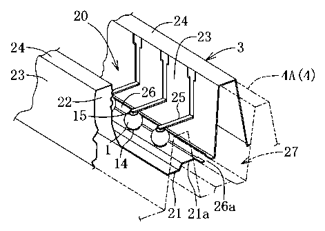
collecting power compared with use of external lenses, however they can be
realized in a relatively simple structure,
[0005]
The US Patent Publication No. 5,482,568 discloses a micromirror solar
battery in which multiple cone-shaped reflecting mirrors are provided in a
case, a solar battery cell having a flat light-receiving surface is placed at
the
bottom of each cone, the sunlight collected by the cone illuminates the top
surface of the solar battery cell, and the heat is released from the underside
of the cone. The flat solar battery cell receives light only at the top
surface
and the reflection loss is not small. Therefore, it is difficult to
sufficiently
increase the incident light usage rate, Furthermore, this micromirror solar
battery has the solar battery cells at the bottom of the case so as to prevent
the solar battery cells from heating up due to light collection.
[0006]
The US Patent Publication No. 5,355,873 discloses a light collection type
solar battery module having spherical solar battery cells. A thin metal
sheet (common electrode) has multiple nearly semispherical recesses with
2
CA 02656080 2008-12-22
PNO0604 (PCT/22006/313577)
reflecting inner surfaces. Lags are formed at the centers of the recesses for
supporting solar battery cells. A conductive mesh supports multiple solar
battery cells at their middle parts. The multiple solar battery cells are set
in multiple recesses and electrically connected to the legs. The multiple
solar battery cells are connected in parallel by the conductive mesh and
sheet. The solar battery cells have no electrode at the top, bottom, or either
end and, therefore, the electric current distribution is uneven within a solar
battery cell, Hence, it is difficult to improve the electric power generation
efficiency. Furthermore, all solar battery cells mounted on the sheet are
connected in parallel, which is inconvenient for increasing the output voltage
of the solar battery module.
[00071
The US Laid-Open Patent Publication No. 2002/0096206 discloses a
solar battery module in which spherical solar battery cells are provided in
the centers of multiple partially spherical recesses, respectively, the
recesses
each have a reflecting inner surface, multiple recesses are formed by two
thin metal plates and an insulating layer between them, and the two thin
metal plates are connected to the positive and negative electrodes of the
spherical solar battery cell at the bottom part thereof to parallel connect
multiple solar battery cells.
[00081
In the above solar battery module, the spherical solar battery cells are
electrically connected to the two thin metal plates at the bottom part. This
causes a drawback that the distance between the upper half light receiving
surface and the positive and negative electrodes of a spherical solar battery
8
CA 02656080 2008-12-22
YNUUOV9 ~C\.a(IL _~~_ ...
cell is large and the resistance loss upon output electric current retrieval
is
increased. Furthermore, all solar battery cells of the solar battery module
are connected in parallel, which is inconvenient for increasing the output
voltage of the solar battery module.
[00091
The inventor of the present application disclosed in the International
Publication No. W002/35612 a rod-shaped light receiving or emitting
semiconductor element having a pair of electrodes on either end face and a
solar battery module using the semiconductor element. However, when this
rod-shaped semiconductor element has a higher length/diameter ratio, the
resistance between the electrodes is increased. Therefore, the ratio is
desirably set for approximately 1.5 or lower.
Patent Document 1: US Patent Publication No, 4,136,436;
Patent Document 2: US Patent Publication No. 6,204,545;
Patent Document 3: Japanese Laid-Open Patent Application Publication.
No. 2001-168369;
Patent Document 4: International Publication No. W003/056633,
Patent Document 5: US Patent Publication No. 5,482,868;
Patent Document 6: US Patent Publication No. 5,355,873;
Patent Document 7: US Laid-Open Patent Publication No,
2002/0096206; and
Patent Document 8: International Publication No. W002/35612.
DISCLOSURE OF THE INVENTION
PROBLEMS TO BE SOLVED BY THE INVENTION
4
CA 02656080 2008-12-22
PNO0604 (YC:1""/Jrzvueh3 i r)
Loo1o]
As in the solar battery modules described in the above publications,
when the bottom end of the p-type or n-type base of the granular solar
battery cell is connected to a first common electrode and the diffusion layer
having a conductivity type different from the base is connected to a second
common electrode at the lower or middle part of the solar battery cell, the
distance between the upper half light receiving surface and the positive and
negative electrodes of a solar battery cell is large and the resistance loss
upon output electric current retrieval is increased.
When the solar battery cell has positive and negative electrodes at
upper and lower ends and a conductive member connected to the positive
electrode and a conductive member connected to the negative electrode are
constituted by separate conductive members such as thin metal plates and
print wirings, the conductive connection mechanism has a complex structure,
which is disadvantageous for production cost,
loon]
When spherical solar battery cells are mounted in the centers of
partially spherical recesses and light is collected by the reflecting surfaces
of
the recesses to illuminate the solar battery cells with the sunlight, there
are
spaces between the recesses, which is disadvantageous in increasing the
usage rate of the incident sunlight. Furthermore, the ratio of the light
receiving surface of the light collecting recesses to the light receiving
surface
of the solar battery cells in a plane view cannot be largely increased.
Therefore, it is difficult to increase the output power in relation to the
light
input to the solar battery module surface,
CA 02656080 2008-12-22
PN00604 (PCT/JP2006/313577)
[0012]
In order to provide lenses circular in a plane view corresponding to the
solar battery cells for light collection in a solar battery module having
granular solar battery cells, the same number of lenses as the solar battery
cells are required. This large number of lenses complicates the structure.
For using a light collection mechanism of the light reflecting type, a
cooling mechanism for effectively cooling the solar battery cells is necessary
because the solar battery cells significantly heat up, When the reflecting
surface is partially spherical, it is difficult to create a smooth passage of
the
cooling fluid. In such a case, it is not easy to improve the cooling
performance.
[0013]
When multiple solar battery cells in a solar battery module are all
connected in parallel, the output voltage of the solar battery module is equal
to the output voltage of the solar battery cells. However, it is desirable
that
the output voltage of the solar battery module is changeable and, in the case
of a light emitting panel in which multiple light emitting diodes are
installed,
the input voltage to the panel is changeable.
[0014]
The objects of the invention of the present application is to provide a
panel-shaped semiconductor module in which the conductive connection
mechanism electrically connecting the semiconductor elements has a
simplified structure, to provides a panel shaped semiconductor module
having a larger light collecting magnification, to provides a panel
semiconductor module advantageous for forming lens parts, and to provide a
6
CA 02656080 2008-12-22
PNJUOV4 ~Yl 1Irrcwv,,, ,,, , õ
panel-shaped semiconductor module advantageous for improving the cooling
performance.
MEANS TO SOLVE THE PROBLEM
[ooml
The panel-shaped semiconductor module relating to the present
invention is a panel-shaped light receiving or emitting semiconductor
module comprising multiple spherical or nearly spherical, granular
semiconductor elements having light receiving or emitting capability and
arranged in multiple rows and columns with their conducting direction
aligned, a conductive connection mechanism electrically connecting in
parallel multiple semiconductor elements in each row and electrically
connecting in series multiple semiconductor elements in each column, and a
conductive inner metal case housing the multiple semiconductor elements
and constituting the conductive connection mechanism.
[0016]
The multiple semiconductor elements each comprises a granular base
consisting of a p-type or n-type semiconductor crystal, another conductive
layer formed on the surface of the base except for one end portion thereof and
having a conductivity type different from the base, a nearly spherical pn
junction formed by the base and another conductive layer, and first and
second electrodes formed on the surface of the base on either side of a center
portion thereof and ohmic-connected to the one end portion of the base and
the another conductive layer, respectively.
[00171
7
CA 02656080 2008-12-22
PNO0604 (PCT/7P2006/313577)
The inner metal caee comprises multiple reflecting surface-forming
grooves each housing a row of multiple semiconductor elements and having a
width decreasing from an opening to a bottom. The reflecting
surface-forming grooves each comprises a light reflecting bottom plate and a
pair of light reflecting oblique plates extending upward from either end of
the bottom plate in an integrated manner.
[00181
The bottom plate has a mount protruding in the center portion in a
width direction, on which a corresponding row of multiple semiconductor
elements is placed and to which one of the first and second electrodes of the
semiconductor elements is electrically connected. Multiple metal finger
leads electrically connected to one of the oblique plates of each reflecting
surface-forming groove and electrically connected to the other of the first
and
second electrodes of the corresponding row of multiple semiconductor
elements are provided, A cutoff slit for cutting off a conductive part
short-circuiting the first and second electrodes of a corresponding row of
multiple semiconductor elements is formed in the bottom plate on one side of
the mount over the entire length of the row.
ADVANTAGES OF THE INVENTION
[00191 {
The granular semiconductor element has a base, another conductive
layer formed on the surface of the base except for one end portion thereof and
having a conductivity type different from that of the base, a pn junction, and
first and second electrodes. The first and second electrodes are provided on
8
CA 02656080 2008-12-22
PN00604 (PCT/JP2006/3135'r/)
the surface of the base on either side of the center thereof and
ohmic-connected to the one end portion of the base and another conductive
layer, respectively. Therefore, the sum of the distances from any point
where carriers (electrons and holes) are generated to the first and second
electrodes can be reduced throughout the semiconductor element, increasing
the electric power generation or light emission output efficiency.
Constituted by the inner metal case, the conductive connection mechanism
electrically connecting multiple semiconductor elements can have a reduced
number of parts and a simplified structure.
[00201
The conductive connection mechanism connects in parallel multiple
semiconductor elements in each row and connects in series multiple
semiconductor elements in each column. When some semiconductor
elements fail for some reason, the current flows through an alternative path
bypassing the failed semiconductor elements, whereby all normal
semiconductor elements continue to work.
[00211
The inner metal case comprises multiple reflecting surface-forming
grooves having a width decreasing from the opening to the bottom. Each
reflecting surface-forming groove comprises a light reflecting bottom plate
and a pair of light reflecting oblique plates. A corresponding row of
multiple semiconductor elements is placed on a mount provided at the center
portion of the bottom plate of the reflecting surface-forming groove. One of
the first and second electrodes of the multiple semiconductor elements is
electrically connected to the mount.
9
CA 02656080 2012-01-27
[00221
In this way, in the case of a light receiving semiconductor module, light
collected by the reflecting surfaces of the reflecting surface-forming grooves
can enter the semiconductor elements. The width of the reflecting
surface-forming
grooves can be three to four times larger or even much
larger than the diameter of the semiconductor elements to increase the ratio
of the reflecting surface-forming groove (light collection part) to the light
receiving surface of the semiconductor elements, thereby increasing the light
collecting magnification. In other words, a smaller number of
semiconductor elements can effectively used to obtain high output power.
Furthermore, the semiconductor elements are placed on a mount
protruding from the center portion of the bottom plate of the reflecting
surface-forming groove. Light reflected by the bottom plate can enter the
lower half of the semiconductor element.
[00231
Each row of multiple semiconductor elements is housed in each of
multiple reflecting surface-forming grooves. Therefore, multiple cylindrical
lenses corresponding to multiple reflecting surface-forming grooves,
respectively, can advantageously used. The multiple reflecting
surface-forming grooves formed by the inner metal case each comprises a
bottom plate and a pair of oblique plates. The inner metal case can be
constituted by a sheet of metal plate, reducing the number of parts and
simplifying the structure,
[00241
Embodiments of the present invention can have the following various
CA 02656080 2012-01-27
FNOOW4 (PCT/JP2006/313577)
structures:
(1) The finger leads are each formed by bending a lower end of a score
cut part formed on an upper half of an oblique plate nearly at right angle.
(2) The cutoff slits of the inner metal case are each formed by punching
out multiple tie bars to form a continuous cutoff slit after one of the first
and
second electrodes of each row of multiple semiconductor elements is
connected to the mount and the other of the first and second electrodes is
connected to the finger lead.
[00261
(3) An outer metal case fitted on an underside of the inner metal case
and having a cross section nearly similar to that of the inner metal case and
an electrically insulating synthetic resin layer interposed between the inner
and outer metal cases are provided and the inner and outer metal cases are
bonded and integrated via the electrically insulating synthetic resin layer.
(4) In the above (3), extensions each extending beyond either end of the
inner metal case by a predetermined length in the row direction are provided
at either end of the outer metal case in the row direction and side plug
blocks
made of an insulating material are fitted in and fixed to case housing grooves
formed in the extensions.
[00261
(5) In the above (4), the reflecting surface forming grooves of the inner
metal case are filled with a transparent flexible insulating synthetic resin
material to embed the semiconductor elements and finger leads therein.
(6) In the above (4), a glass or synthetic resin cover member fixed to the
inner metal case and side plug blocks for covering a top of the inner metal
11
CA 02656080 2008-12-22
PNO0604 (PCT/JP20061313577)
case is provided.
[0027]
(7) In the above (6), the cover member has multiple cylindrical lens
parts corresponding to multiple rows of semiconductor elements,
respectively.
(8) A duct member forming a passage for a cooling fluid is provided on
the outer surface of the outer metal case.
(9) An antireflection coating is formed on surfaces of the semiconductor
elements except for the areas where the first and second electrodes are
provided.
[0028]
(10) The base of the semiconductor elements is made of a p-type Si
monocrystal or Si polycrystal, the other conductive layer is formed by
diffusing P, Sb, or As as an n-type impurity, and the semiconductor elements
are solar battery cells.
(11) The base of the semiconductor elements is made of an n-type Si
monocrystal or Si polycrystal, the other conductive layer is formed by
diffusing B, Ga, or Al as a p-type impurity, and the semiconductor elements
are solar battery cells.
(12) The semiconductor elements are light emitting diode elements
having light emitting capability.
BRIEF DESCRIPTION OF THE DRAWINGS
[00291
Fig.1 is a perspective view of a solar battery module relating to
12
CA 02656080 2008-12-22
PN00604 (PCl'/JP2006/313577)
Embodiment 1 of the present invention;
Fig.2 is a cross-sectional view at the line II-II in Fig. 1;
Fig.3 is a cross-sectional view at the line III-III in Fig.l;
Fig.4 is a plane view of the solar battery module with a cover member
removed;
Fig.5 is an enlarged view of the core part of Fig.4;
Fig.6 is a perspective view of the side plug block;
Fig.7 is a perspective view of the core part of the reflecting
surface-forming groove of the inner metal case;
Fig.8 is an enlarged cross-sectional view of the semiconductor element;
Fig.9 is a circuit diagram equivalent to the conductive connection
mechanism;
Fig.10 is a perspective view equivalent to Fig.7 of a modified
embodiment;
Fig.11 is a cross-sectional view equivalent to Fig.2 of a solar battery
module relating to Embodiment 2; and
Fig.12 is an enlarged cross-sectional view of a light emitting
semiconductor element relating to Embodiment 3;
DESCRIPTION OF NUMERALS
[0030]
M, Ma solar battery module (panel-shaped semiconductor module)
1 semiconductor element
2 conductive connection mechanism
3 inner metal case
13
CA 02656080 2008-12-22
PNO0604 (PCT/JP2006/313577)
4 outer metal case
4A extension
cover member
5a cylindrical lens part
6 insulating synthetic resin material
7 synthetic resin layer
8 side plug block
11 base
12 diffusion layer
13 pn junction
14 positive electrode
negative electrode
16 antireflection coating
reflecting surface-forming groove
21 bottom plate
21a mount
22, 23 oblique plate
25, 25A finger lead
26 cutoff slit
35 duct member
40 light emitting semiconductor element
41 base
42 diffusion layer
43 pn junction
44 positive electrode
14
CA 02656080 2008-12-22
PNO0604 (P(:17JP2UU61J1:J5_I_/)
45 negative junction
46 antireflection coating
BEST MODE FOR IMPLEMENTING THE INVENTION
[0081]
The panel-shaped semiconductor module of the present invention has a
basic structure comprising multiple granular light receiving or emitting
semiconductor elements arranged in multiple rows and columns, a
conductive connection mechanism connecting in parallel multiple
semiconductor elements in each row and connecting in series multiple
semiconductor elements in each column, and an inner metal case housing the
multiple semiconductor elements and constituting the conductive connection
mechanism, wherein the inner metal case has multiple reflecting
surface-forming grooves housing multiple rows of semiconductor elements,
respectively, and having a width decreasing from an opening to a bottom.
EMBODIMENT 1
[0032]
The panel-shaped semiconductor module relating to Embodiment 1 is a
solar battery module (solar battery panel) receiving the sunlight and
generating electric power. This solar battery module M will be described
with reference to the drawings. As illustrated in Figs. 1 to 5, the solar
battery module M comprises multiple granular semiconductor elements 1
having light receiving capability, a conductive connection mechanism 2
electrically connecting the semiconductor elements 1 (see Fig.9), an inner
CA 02656080 2008-12-22
r1VVVOVw [PbaNrcvvvr~a~~r rr
metal case 3 housing the multiple semiconductor elements 1, an outer metal
case 4 fitted on the underside of the inner metal case 3, a transparent cover
member 5 covering the top of the inner metal case 3, a silicone rubber
insulating synthetic resin material 6 introduced in the inner metal case 3, a
synthetic resin layer 7 bonding the inner and outer metal cases 3 and 4
together, multiple side plug blocks 8, and two reinforcement plates 9.
[00331
As illustrated in Fig. 8, the semiconductor element I is a nearly
spherical (a partial sphere close to a sphere), granular solar battery cell
having a center la. The semiconductor element 1 has a nearly spherical
base 11 of p-type silicon monocrystal, an n-type diffusion layer 12 (which
corresponds to another conductive layer having a conductivity type different
from that of the base 11), a pn junction 13, positive and negative electrodes
14 and 15, and an antireflection coating 16. The semiconductor element 1
receives the sunlight and generates photovoltaic power of approximately 0.5
to 0.6 V.
(0034]
The base 11 is a p-type silicon monocrystal sphere having a diameter of
approximately 1.8 mm with a flat circular section Ila (for example having a
diameter of approximately 0.6 to 1.0 mm) at the bottom (one end portion).
The diffusion layer 12 is an n-type conductive layer formed by
thermal- diffusing P (phosphorus) as an n-type impurity in the surface part of
the base 11 to a depth of 0.5 to 1.0 gm except for a part including the flat
section lla and its vicinity.
(0036]
16
CA 02656080 2008-12-22
The p-type base 11 and n-type diffusion layer 12 together form a nearly
spherical (a partial sphere closer to a sphere) pn junction 13. The pn
junction 13 surrounds most of the periphery of the semiconductor element 1
around the center la. A circular positive electrode 14 having a diameter of
approximately 0.4 mm is provided on the flat section lla of the base 11. A
circular negative electrode 15 having a diameter of approximately 0.4 mm is
provided on the surface of the base 11 at a position across the center la from
the positive electrode 14. The positive electrode 14 is formed by firing a
paste of silver mixed with aluminum. The negative electrode 15 is formed
by firing a paste of silver mixed with a small amount of antimony. The
positive and negative electrodes 14 and 15 are provided on the surface of the
base 11 on either side of the center la in parallel to each other. The
positive
eleetrodel4 is ohmic-connected to the base 11 and the negative electrode 15
is ohmic-connected to the diffusion layer 12.
[00361
An antireflection coating 16 consisting of a silicon oxide coating or
silicon nitride coating is formed on the surface of the semiconductor element
1 except for the areas where the positive and negative electrodes 14 and 15
are provided for the purpose of antireflection and silicon surface
passivation.
When the semiconductor element 1 is illuminated with the sunlight bin and
the silicon monocrystal of the base 11 absorbs the sunlight, carriers
(electrons and holes) are generated, the pn junction 13 separates the
electrons from the holes, and photovoltaic power is generated between the
positive and negative electrodes 14 and 15. Even if the incident direction of
the incoming sunlight changes, the semiconductor element 1 has uniform
17
CA 02656080 2008-12-22
light reception sensitivity and efficiently receives the sunlight bm in a wide
range of directions and generates electric power (see Fig.2).
[0037]
The positive and negative electrodes 14 and 15 are positioned nearly
symmetrically about the center la of the base 11, For carriers generated in
the base 11 upon receiving the sunlight bm, for example, the sum of the
distances from any point of the diffusion layer 12 to the positive and
negative
electrodes 14 and 15 is nearly equal. The photoelectric current distribution
is uniform with regard to the center la of the base 11 and resistance loss due
to uneven distribution can be reduced.
[0038]
As illustrated in Figs. 2, 4, 5, and 7, multiple semiconductor elements 1
are arranged in multiple rows and columns in multiple reflecting
surface forming grooves 20 of the inner metal case 3 with their conducting
direction aligned. Multiple semiconductor elements 1 are arranged with
their positive electrode 14 at the bottom and their negative electrode 15 at
the top, whereby they have a vertically downward conducting direction.
[0039]
The inner metal case 3 is formed by punching a thin plate (for example
having a thickness of 0.4 mm) of iron/nickel alloy (Ni 42 % and Fe 58 %) into
a monolithic item in a press machine with a specifically-shaped die. The
light receiving inner surface of the inner metal case 3 is mirror finished or
either gold or silver plated for improved light reflecting performance.
[0040]
As illustrated in Figs. 2, 4, 5, and 7, the inner metal case 3 comprises
18
CA 02656080 2008-12-22
rmjvuut
the same number of gutter-like reflecting surface-forming grooves 20 as the
rows of semiconductor elements 1, and flanges 3f and coupling terminals 3a
at the right and left ends. The reflecting surface-forming grooves 20 have
an inverted trapezoidal cross section having a width linearly decreasing from
the opening to the bottom. Each reflecting surface-forming groove 20
comprises a bottom plate 21 and a pair of oblique plates 22 and 23 extending
upward from either end of the bottom plate 21. The top ends of the oblique
plates 22 and 23 of adjacent reflecting surface-forming grooves 20 are
coupled by a narrow coupling plate 24.
[0041]
Each bottom plate 21 has a mount 21a having a trapezoidal cross section
and protruding upward at the center portion in the width direction.
Multiple semiconductors 1 of a corresponding row are placed on the mount
21a at proper intervals (for example at intervals of the diameter of the
semiconductor elements 1). Their positive electrodes 14 are bonded to the
mount 21a using a conductive epoxy resin for electrical connection.
Multiple finger leads 25 integrally extend from the middle part of the right
oblique plate 23 of each reflecting surface- forming groove 20 to be
electrically connected to the negative electrodes of the corresponding row of
multiple semiconductor elements 1, respectively. The negative electrodes
15 of the semiconductor elements 1 are bonded to the finger leads 25 using a
conductive epoxy resin for electric connection. The finger leads 25 are each
formed by bending the lower end of a score cut part formed on the upper half
of the right oblique plate 23 at right angle (see Fig.7),
[0042]
19
CA 02656080 2008-12-22
YNUUbUL+kr4i/rr4wo,ai3 iii
As illustrated in Fig.2, a cutoff slit 26 is formed in each bottom plate 21
on the right side of the mount 21a over the entire length in the row direction
(the entire length of the inner metal case 3) for cutting off the conduction
from the multiple positive electrodes 14 of the corresponding row of multiple
semiconductor elements 1 to the multiple finger leads 25 so as to cut off the
conductive part short-circuiting between the positive and negative electrodes
14 and 15 of the corresponding row of multiple semiconductor elements 1.
Each cutoff slit 26 is formed by punching out the tie bars (not illustrated)
of
multiple tie bar punch-out portions 26a to form a continuous cutoff slit 26
after the positive electrodes 14 of each row of multiple semiconductors 1 are
bonded to the mount 21a and the negative electrodes 15 are bonded to the
finger leads 25.
[0043]
As described above, after multiple semiconductor elements 1 are
arranged in multiple rows and columns in the inner metal case 3 with their
positive electrodes 14 connected to the mount 21a and their negative
electrodes 15 connected to the finger leads 25 and the cutoff slit 26 is
formed
in the bottom plate 21 of each reflecting surface-forming groove 20, the
semiconductor elements 1 in each row are connected in parallel by the inner
metal case 3 and multiple finger leads 25 and multiple semiconductor
elements in each column are connected in series by the inner metal case 3
and multiple finger leads 25. In this way, the inner metal case 3 including
multiple finger leads 25 constitutes a conductive connection mechanism 2
electrically connecting in parallel multiple semiconductor elements 1 in each
row and electrically connecting in series multiple semiconductor elements 1
CA 02656080 2008-12-22
fir. aira =,vv
rIVVVwrt
in each column (see Fig.9).
[0044)
As illustrated in Figs, 2 to 5 and 7, an outer metal case 4 having a cross
section nearly similar to the inner metal case 3 is fitted on the underside of
the inner metal case 3. The outer metal case 4 is formed by forming the
same iron/nickel alloy plate (for example having a thickness of 0.4 mm) as
the inner metal case 3. The outer metal case 4 has flanges 4f at either end
in the column direction. The outer metal case 4 has at either end in the row
direction extensions 4A extending beyond either end of the inner metal case
3 in the row direction by a predetermined length, The inner and outer
metal cases 3 and 4 are bonded and integrated together via an electrically
insulating synthetic resin layer 7 (having a thickness of 0.1 to 0.5 mm)
consisting of a heat-resistant insulating adhesive such as polyimide resin
introduced between them.
[00451
As illustrated in Figs. 3 and 5 to 7, side plug blocks 8 made of an
insulating material (for example a ceramic or glass material) are fitted in
case housing grooves 27 formed in the extensions 4A of the outer metal case 4
and bonded thereto using a heat-resistant insulating synthetic resin
adhesive such as polyimide resin for completely sealing the ends of the inner
metal case 3 in the row direction. The side plug blocks 8 have an oblique
inner surface Sa tilted similarly to the oblique plates 22 and 23 for improved
light reception.
As illustrated in Fig.2, a flexible transparent silicone rubber insulating
synthetic resin material 6 is introduced into the reflecting surface-forming
21
CA 02656080 2008-12-22
PNUUbU4 (rGif.FLUU(J/31]J 11)
grooves 20 of the inner metal case 3 so as to embed the semiconductor
elements 1 and finger leads 25, degassed under reduced pressure, and cured.
[0046]
As illustrated in Figs. 1, 2, and 3, a transparent glass or synthetic resin
cover member 5 covering the top of the inner metal case 3 and fixed to the
inner metal case 3 and side plug blocks 8 is provided. The cover member 5
is desirably made of white reinforced glass or borosilicate glass. The cover
member 5 has multiple cylindrical lens parts 5a corresponding to multiple
rows of semiconductor elements 1, respectively, at the upper part and
engaging parts 5b fitted in the upper parts of multiple reflecting
surface-forming grooves 20 at the lower part. The cover member 5 has flat
parts 5c at right and left ends in Figs. 1 and 2.
[0047]
In order to fix the cover member 5 to the inner metal case 3, the cover
member 5 is attached to the inner metal case 3 with a thick layer of silicone
resin applied on the entire underside surface of the cover member 5, whereby
the cover member 5 is bonded to the silicone rubber 6 (insulating synthetic
resin material) and oblique plates 22 and 23 of multiple reflecting
surface-forming grooves 20, to other top surface portions of the inner metal
case 3, and to the inner sides of multiple side plug blocks 8. Then, the
entire structure is heated under reduced pressure to cure the silicone resin
adhesive/sealing material 29. Here, the inner space of each reflecting
surface-forming groove 20 is completely filled with the silicone rubber 6 and
adhesive/sealing material 29. The right and left flat parts 5c of the cover
member 5 and flanges 3f and 4f are fastened together by multiple metal or
22
CA 02656080 2008-12-22
F1\L/VIJT~1 U i!JF zvvv.-a_,_' . . synthetic resin bolts 30, Here, the bolts
30 are insulated from the flanges
3f.
[00481
As illustrated in Figs. 1 and 3, a polyimide resin reinforcement plate 9
closing the top of multiple side plug blocks 8 is provided and fixed using the
same adhesive/sealing material as the above described adhesive/sealing
material 29 for reinforcing the integrity of the multiple side plug blocks 8
and inner metal case 3.
As illustrated in Figs. 1 to 5, coupling terminal plates 3a are exposed at
right and left ends of the inner metal case 3 and extend over the entire
length in the row direction for electrically connecting multiple solar battery
modules M or coupling the output retrieval lines. Each coupling terminal
plate 3a has multiple bolt holes 31.
[0049]
Fig.9 shows an equivalent circuit to multiple semiconductor elements 1
and the conductive connection mechanism 2 of the above described solar
battery module M. The semiconductor elements 1 are presented by diodes
1A. In this equivalent circuit, multiple diodes 1A in each row are connected
in parallel and multiple diodes 1A in each column are connected in series,
whereby all diodes are serial/parallel-connected in a mesh circuit.
Photovoltaic power is generated between the positive and negative electrode
terminals 18 and 19.
[0050]
Functions and advantages of the above described solar battery module
M will be described hereafter.
23
CA 02656080 2008-12-22
PN00604 (PCT/JP2006/313577)
The nearly spherical semiconductor elements 1 of this solar battery
module M are nearly symmetric about their centers and can receive the
sunlight in any direction (directions over approximately 270 degrees),
exhibiting sensitivity for a wide angle of light reception. The inner metal
case 3 has multiple reflecting surface-forming grooves 20 having a width
linearly decreasing from the opening to the bottom. A row of multiple
semiconductors 1 is placed at the bottom of each reflecting surface-forming
groove 20. The reflecting surface-forming groove 20 has a light reflecting
inner surface. Hence, the sunlight falls on the semiconductor elements 1
after multiple reflections on the inner surface of the reflecting
surface-forming grove 20.
[00511
The width at the opening of the reflecting surface-forming groove 20 can
be 3 to 15 times larger than the diameter of the semiconductor elements 1 so
that the horizontal area ratio of the reflecting surface-forming groove 20
(light collection part) to the projected light receiving cross section of the
semiconductor elements 1 in each row is increased for larger collecting power.
Therefore, the necessary number or light receiving area of semiconductor
elements 1 can be reduced, which is advantageous for silicon cost and
production cost. Furthermore, the semiconductor elements 1 are fixed on
the mount 21a of the bottom plate 21 of the reflecting surface-forming groove
20. Light reflected by the bottom plate and scattered light can easily enter
the semiconductor elements 1; the semiconductor elements 1 have a larger
light receiving range. Additionally, the semiconductor elements 1 can
easily be positioned and fixed using a conductive epoxy resin.
24
CA 02656080 2008-12-22
[0052]
The transparent flexible silicone rubber 6 is used to embed the
semiconductor elements 1 in the reflecting surface-forming groove 20. The
semiconductor elements 1 are completely protected from external impact or
moisture or air. The silicone rubber 6 absorbs expansion or shrinkage of the
solar battery module M due to temperature changes. The refractive index of
the silicone rubber 6 is close to that of the cover member 5 and
antireflection
coating 16, which reduces reflection loss at the interface. Furthermore, the
silicone rubber 6 optically couples the semiconductor elements 1, which
makes it easier for not only collected direct light but also scattered light
resulting from multiple internal reflections to enter the semiconductor
elements 1.
[00531
In addition, the cover member 5 has cylindrical lens parts 5 each
corresponding to a reflecting surface-forming groove 20. The sunlight
energy intensity can be approximately 5 to 15 times increased through the
light collection by the cylindrical lens parts 5a. The output power of the
semiconductor elements 1 can be approximately 7 to 15 times increased
through the light collection by the cylindrical lens parts 5a and light
collection by the reflecting surface-forming grooves 20 compared with the
case of no light collection by them.
[00641
The conductive connection mechanism 2 connects in parallel multiple
semiconductor elements 1 in each row and connects in series multiple
semiconductor elements 1 in each column. When some semiconductor
26
CA 02656080 2008-12-22
!r cn,out tr' i,Jr c.vvw.J I a.,. 1i
elements 1 fail for some reason (disconnection, poor connection, in shade,
etc.), the current flows through an alternative path bypassing the failed
semiconductor elements, whereby all normal semiconductor elements 1
continue to work.
[0055]
The semiconductor elements 1 have a nearly spherical shape. The
positive and negative electrodes 14 and 15 are provided on the surface on
either side of the center and ohmic-connected to the base 11 or to the
diffusion layer 12. Therefore, the sum of the distances from any point of the
diffusion layer 12 to the positive and negative electrodes 14 and 15 is nearly
equally and small. The electric resistance between the positive and
negative electrodes 14 and 15 can be maintained small. The generated
electric power output efficiency can be improved. Furthermore, the
conductive connection mechanism is constituted by the inner metal case 3
including multiple finger leads 25, the conductive connection mechanism 2
can have a simplified structure.
[0056]
The solar battery module M easily heats up and, when heating up, its
power generation efficiency is lowered. The inner and outer metal cases 3
and 4 are made of a thin metal plate and integrated together. The inner
metal case 3 has multiple gutter-like reflecting surface-forming grooves 20,
of which the inner surfaces serve as a reflector/light collector and the back
sides serve as a radiator, Particularly, the reflecting surface-forming
grooves 20 have a W-shaped cross section with the upwardly bulging mount
21a of the bottom plate 21, improving rigidity and strength and increasing
26
CA 02656080 2008-12-22
ri~wwr ~r'.itJrcuuu/J1JJ i i
the heat dissipation area. Thermal energy absorbed by the solar battery
module M is transmitted through the inner metal case 3, polyimide synthetic
resin thin layer 7, and outer metal case 4 and released outside.
[0057]
The reflecting surface-forming grooves 20 of the inner metal case 8 serve
both as a container to receive the silicone rubber F and as a reception part
for
engaging with and positioning the engaging part 5b of the cover member 5.
The finger leads 25 corresponding to the respective semiconductor
elements 1 are integrally formed on one oblique plate 23 of a reflecting
surface-forming groove 20. The finger leads 25 are bonded to the negative
electrodes 1 of the semiconductors 1 using a conductive epoxy resin. In this
way, separate connection leads can be omitted.
[0058)
The finger leads 25 can be produced as score cut parts formed on the
oblique plate 23 while the inner metal case 3 is produced. Upon assembly,
the positive electrodes 14 of each row of multiple semiconductors 1 are
bonded to the mount 21a using a conductive epoxy resin and then the score
cut parts are bent to form the finger leads 25, which are then bonded to the
negative electrodes 15 of the semiconductor elements 1 using a conductive
epoxy resin. After all finger leads 25 are bonded to the negative electrodes
15 of the semiconductor elements 1 in the solar battery module M, the tie
bars (not illustrated) connecting multiple tie bar punch-out portions 26a are
punched out. The finger leads 25 also serve as a marking for positions
where the semiconductor elements 1 are placed. The multiple tie bars serve
to maintain the integrity of the inner metal case 3 while the inner metal case
27
CA 02656080 2008-12-22
3 is formed and allow the inner metal case 3 to be formed from a sheet of
metal plate, reducing the number of parts and simplifying the structure.
[0059]
Partial modifications of the above described embodiment will be
described hereafter.
1) As illustrated in Fig.10, in place of the finger leads 25, connection
pieces 50 formed separately from the inner metal case 3 by punching out a
conductive metal, such as iron and nickel, thin plate are provided at
positions corresponding to the semiconductor elements 1 and finger leads
25A horizontally extending to the left are formed at the lower end of the
connection pieces 50.
[0060]
The connection piece 50 is obtained by integral-forming a coupling
section 50a to be bonded to the coupling part 24 of the inner metal case 3,
oblique sections 50b and 50c provided on either side of the coupling section
50a to be bonded to the oblique plates 22 and 23, and the finger lead 25A.
For example, the connection piece 50 is bonded to the coupling part 24 and
oblique plates 22 and 23 on the either side thereof using a conductive epoxy
resin and the leading end of the finger lead 25A is bonded to the negative
electrode 15 of the corresponding semiconductor element 1 using a
conductive epoxy resin for electric connection. Here, the coupling section
50a and oblique sections 50b and 50b have a width of for example 2 to 3 mm
and the finger lead 25A has a width of for example 0.5 to 1 mm.
[0061]
2) The above described solar battery module M has nine reflecting
28
CA 02656080 2008-12-22
rNWpUw ~r~ ir~rwvor~l r u
surface-forming grooves 20. However, several tens of rows and several tens
of columns can be provided. The materials of the inner metal case 3,
positive and negative electrodes 14 and 16, and outer metal case 4 and
various synthetic resin materials are not restricted to the above described
embodiment and can be changed by a person of ordinary skill in the field as
appropriate.
[00621
The diameter of the base 11 of the semiconductor elements 1 is not
restricted to the above described embodiment and can be approximately 1.0
to 2.5 mm. The intervals of the semiconductor elements 1 mounted in each
reflecting surface-forming groove 20 can be smaller or larger than the
intervals in the figure.
[00631
3) The base 11 of the semiconductor elements 1 can be a p-type silicon
polycrystal and the n-type impurity forming the diffusion layer 12 can he Sb
or As. Alternatively, the semiconductor elements 1 can comprise an n-type
silicon monocrystal or polycrystal base 11 and a diffusion layer 12 having a
p-type impurity such as B, Ga, and Al. The pn junction 13 is not necessarily
created by the diffusion layer 12. The pn junction 13 can be created by
forming a film on the surface of the base 11 or injecting ions in the surface
of
the base 11 to form another conductive layer having a conductivity type
different from that of the base 11.
4) The flat section 11a of the base 11 of the semiconductor elements 1
can be omitted. The base 11 can be spherical and the positive electrode 14
has the same form as the negative electrode 15. In such a case, the positive
29
CA 02656080 2008-12-22
and negative electrodes can be different in size or made of metal materials of
different colors so that they can be distinguishable from each other.
[0064]
5) The cross section of the reflecting surface-forming grooves 20 of the
inner metal case 3 is not particularly restricted to the above described
embodiment. Any groove having a width linearly or nonlinearly decreasing
from the opening to the bottom for light collection capability can be used.
The inner metal case 3 of a solar module M can be constituted by multiple
formed metal plates.
EMBODIMENT 2
[0.065]
A solar battery module Ma (panel shaped semiconductor module)
illustrated in Fig.11 has a duct member 35 fitted on the underside of the
above described solar battery M. The solar battery module Ma has the same
structure as the solar battery module M except for the duct member 35.
Therefore, the same components are designated by the same reference
numerals and their explanation will be omitted. The duct member 35 has
an inverted trapezoidal body 35a forming a coolant passage 36 together with
the outer metal case 4 for a forced or natural flow of a coolant fluid such as
air and cooling water, and flanges 35f extending from right and left ends of
the body 35a. The flanges 35f are each fastened to the flat plate 5c of the
cover member 5, flange 3f of the inner metal case 3, and flange 4f of the
outer
metal case 4 by multiple bolts 30 from below,
[00661
CA 02656080 2008-12-22
With a coolant such as air and cooling water running through the
coolant passage 36, the inner and outer metal cases 3 and 4 and
semiconductor elements 1 can effectively be cooled. Particularly, the inner
and outer metal cases 3 and 4 have intricate outer surfaces and accordingly
have a large heat transfer area. The semiconductor elements 1 are close to
the coolant. Therefore, a high cooling performance can be obtained.
EMBODIMENT 3
[0067]
This embodiment relates to light emitting semiconductor elements (light
emitting diodes) applied to a high output power light emitting diode module
with a reflecting mechanism, which is a panel-shaped semiconductor module.
This light emitting diode module with a reflecting mechanism comprises
light emitting semiconductor elements in place of the semiconductor
elements 1 of the above described solar battery module M.
[0068]
The light emitting semiconductor element will be described hereafter.
As illustrated in Fig. 12, a light emitting semiconductor element 40 has
a nearly spherical (a partial sphere close to a sphere) base 41 consisting of
an
n=type semiconductor crystal, a p-type diffusion layer 42 formed in the
surface part of the base 41 (which corresponds to another conductive layer
having a conductivity type different from the base), a nearly spherical pn
junction 43 formed by the base 41 and diffusion layer 42, positive and
negative electrodes 44 and 45, and an antireflection coating 46.
[0069]
31
CA 02656080 2008-12-22
The base 41 consists of an n-type GaAs crystal sphere having a diameter
of 1.0 mm with a flat circular section 41b (having a diameter of
approximately 0.2 to 0.5 mm) perpendicular to the vertical line passing
through the center 41a at the bottom end. The diffusion layer 42 is formed
by thermal diffusing a p-type impurity Zn (zinc) in the surface part of the
base 41 to a depth of 0.5 to 1.0 gm except for a circular part including the
flat
section 41b and its vicinity, The positive and negative electrodes 44 and 45
are made of silver-based materials. The negative electrode 45 is provided
on the flat section 41b at the center portion and ohmic-connected to the base
41, The positive electrode 44 is provided on the surface of the diffusion
layer 42 at a position across the center 41a of the base 41 from the negative
electrode 45 and ohmic-connected to the diffusion layer 42.
[0070]
An antireflection coating 46 consisting of a thin silicon oxide coating or
silicon nitride coating and having passivation function is formed on the
surface of the base 41 and diffusion layer 42 except for the areas where the
positive and negative electrodes 44 and 45 are formed. The light emitting
semiconductor element 40 emits infrared light from near the pn junction 42
when a forward current runs from the positive electrode 44 to the negative
electrode 45. Because the pn junction 43 has a partial spherical shape close
to a sphere, the generated infrared light crosses the surface of the
semiconductor element 40 at right angle and exits outside, Therefore,
internal reflection loss of the light is reduced and light emission efficiency
is
improved compared with the prior art light emitting diode having a flat pn
junction.
32
CA 02656080 2008-12-22
[0071]
In the high output power light emitting diode module with a reflecting
mechanism in which the light emitting semiconductor elements 40 are
installed in place of the semiconductor elements 1 of the above described
embodiment, when a forward current is supplied from the positive terminal
to the negative terminal, the forward current runs through all light emitting
semiconductor elements 40, leading to emission of infrared light. The
infrared light emitted from the light emitting semiconductor elements 40
exits outside through the cylindrical lens parts 5a of the cover member 5
directly from the reflecting surface-forming groove 20 or after reflected on
the reflecting surfaces.
[0072]
The light emitting semiconductor elements 40 increase their light
output as the forward current is increased. However, conversion loss leads
to heat generation and to rise in temperature, which reduces light emission
efficiency. This light emitting diode module is excellent in heat dissipation
as the above described solar battery module M and therefore reduces the rise
in the module temperature. Hence, a large light output can be obtained by
supplying a large current to a smaller number of light emitting
semiconductor elements 40, reducing the light emitting diode module
production cost.
The light emitting diode module can be a useful industrial infrared
generation apparatus such as a light source of medical equipment, various
infrared sensors, and infrared lighting.
[0073]
33
CA 02656080 2008-12-22
Partial modifications of the above described light emitting diode module
and light emitting semiconductor element 40 will be described hereafter.
1) The light emitting diode module also can have a duct member as the
above described solar battery module Ma.
[00741
2) Various light emitting diodes are produced using various
semiconductor materials and emit light of various light emission
wavelengths according to the characteristics of the semiconductor material.
Any light emitting diode produced using such various semiconductor
materials can be used. Other than infrared light, light emitting diodes
emitting visible or ultraviolet light may also be used.
[00751
The base can be constituted by a semiconductor crystal for example
selected from GaAlAs, GaP, InGaP, GaN, GaInN, and SiC, SiC is a
hexagonal crystal and yields a hexagonal column single-end crystal. Such a
hexagonal column single-end crystal can be used to constitute the base.
The pn junction of the light emitting semiconductor element is not
necessarily created by a diffusion layer. The pn junction can also be created
by forming a film on the surface of the base or injecting ions in the surface
of
the base to create another conductive layer having a conductivity type
different from that of the base. The flat section 41a of the base 41 of the
light emitting semiconductor element 40 can be omitted. In such a case, the
base 41 is spherical.
INDUSTRIAL APPLICABILITY
34
CA 02656080 2008-12-22
[00761
The solar battery module is applicable to various fields as a solar power
generation apparatus. The light emitting module is applicable to various
fields according to the type of light generated.