Note: Descriptions are shown in the official language in which they were submitted.
CA 02656641 2010-03-16
WO 2008/006056 PCT/US2007/072935
BUCKLING CLAMSHELL CONTAINER
FIELD OF THE INVENTION
The present invention relates generally to containers for receiving,
containing, and selectively dispensing a plurality of objects via automated
processes. More specifically, the present invention provides a partially
flexible
buckling clamshell container for receiving metered seed sample aliquots. The
container of the present invention may be selectively opened by automated
processes by elastically deforming at a predetermined point to release one or
more
objects contained therein when the container is inverted and subjected to a
compressive opening force.
BACKGROUND OF THE INVENTION
A number of packaging containers have been developed for holding and
sealing products and/or individual parts or components. For example,
conventional vacuum molded or thermoformed plastic containers (such as those
produced to package small hardware components such as screws and/or nails)
often include a container body defining an aperture and an attached lid that
is
designed to selectively close the aperture. For example, some conventional
packaging containers further include corresponding flange portions (extending
from the container body and the lid, respectively) that are designed to fit
snugly
against one another so as to seal the container body. Some conventional
packaging
containers further include an adhesive material disposed between flange
portions
for sealing the lid closed about the aperture defined by the container body.
Such conventional containers are often well-suited for providing a robust
package that may provide adequate protection to the product contained therein.
However, once closed and sealed, such conventional packages are not well
suited
for re-opening, much less re-opening by automated processes. Thus,
conventional
containers such as the type described generally above may not be well-suited
to
serve as an aliquot container for receiving, selectively holding, and
selectively
dispensing one or more particles or components as part of an intermediate
research
and/or manufacturing step. For example, manual dexterity and/or the use of a
cutting tool, may be required to open and remove products from many
-l-
CA 02656641 2008-12-30
WO 2008/006056 PCT/US2007/072935
conventional packaging containers (especially those that include corresponding
flange portions and adhesives disposed therebetween). In addition, such
containers
are not well suited for re-opening (after being closed) by simple automated
processes (such as the application of a compressive force on the container)
because
of the constant interference fit between the lids and reservoirs of
conventional
packaging containers.
Thus in order to facilitate the selective capture, retention, and dispensing
of
particulate components by simple automated and/or manual processes, there is a
need in the art for a packaging container that not only allows for the quick
and
complete capture and retention of particulate components, but also a container
that
may be quickly and easily re-opened so as to selectively dispense the
particulate
components held therein upon the application of a simple automated and/or
manual
compressive force to the container. For example, there exists a need in the
art for
an easily-opened clamshell container for segregating and selectively
dispensing an
aliquot of a particular seed type using mainly automated processes.
Furthermore,
there exists a need for a packaging container that is not only easily closed
and re-
opened as described above, but that is easily and economically manufactured
and
provided with a lid and reservoir portion that are provided in a one-piece
assembly
such that the lid may remain connected to the reservoir portion of the
container
even as the container is selectively opened to disperse the particulate
components
held therein.
SUMMARY OF THE INVENTION
The embodiments of the present invention satisfy the needs listed above
and provide other advantages as described below. Embodiments of the present
invention may include a package assembly for selectively containing and
releasing
a particulate aliquot (such as one or more selected types of agricultural
seeds).
According to some embodiments, the package assembly comprises first and second
portions which cooperate to contain the aliquot, wherein a pair of flexure
channels
are defined in opposing sides of at least one of the first or second portions,
the
flexure channels cooperating to define a flexure axis extending through the
pair of
flexure channels, the package assembly being configured such that when a force
is
applied to the package assembly, approximately perpendicularly to the flexure
axis, at least one of the first or second portions flex outwardly about the
flexure
-2-
CA 02656641 2008-12-30
WO 2008/006056 PCT/US2007/072935
axis so that the first and second portions separate in response to the force.
At least
one concave portion may be located on a flange portion defined by at least one
of
the first or second portions, the concave portion defining an aperture
configured to
receive an opening tool for encouraging the first and second portions to
separate.
At least one corresponding concave portion may be located on a second flange
portion of the package assembly and adapted to substantially align with the
other
concave portion to define an aperture configured to receive an opening tool
for
encouraging the first and second portions to separate. The first and second
portions may define first and second flange portions and the package assembly
may further comprise a notch portion located on one of the first or second
flange
portions, the notch portion configured to allow a disengaging tool to apply a
substantially normal force against the other of the first or second flanges,
for
encouraging the first and second portions to separate. In some embodiments,
the
first and second portions are held together in a closed position through an
interference fit.
According to other embodiments, the package assembly may comprise a
container portion defining an opening and including at least two opposing
sides,
and a cover portion configured to cooperate with the container portion to
selectively close the opening. Some embodiments of the package assembly may
further comprise a reinforcing ridge portion operably engaged about a
perimeter of
the cover portion. In addition, the reinforcing ridge portion may be
configured to
be capable of engaging an inner periphery of the opening, in an interference
fit, so
as to selectively close the opening. Furthermore, the reinforcing ridge
portion may
also define a pair of flexure channels on opposing sides of the cover portion.
The
flexure channels may thus cooperate to define a flexure axis extending
substantially perpendicularly to a pair of opposing sides of the cover portion
defining the flexure channels such that the flexure axis is substantially
parallel to
the at least two opposing sides of the container portion. Furthermore, the
cover
portion may be configured to be capable of flexing outwardly from the
container
portion about the flexure axis when a force is applied to the at least two
opposing
sides of the container portion. Thus, the cover portion (and the reinforcing
ridge
portion extending therefrom) may also disengage from the inner periphery of
the
opening so that the cover portion disengages from the container portion in
response
to the force. In some embodiments, the container portion, the cover portion,
and
-3-
CA 02656641 2008-12-30
WO 2008/006056 PCT/US2007/072935
the opening defined by the container portion may be constructed and formed to
have a substantially rectangular shape.
Some package assembly embodiments of the present invention may further
comprise a hinge portion operably engaged between an edge of the cover portion
and one of the at least two opposing sides of the container portion such that
the
cover portion may remain connected to the container portion even as the cover
portion is disengaged from closing engagement with the container portion as
described above. Furthermore, in some embodiments, the container portion, the
cover portion, the reinforcing ridge, and the hinge portion may be
substantially
integrally formed as a single one-piece assembly. For example, in some
embodiments, the container portion, the cover portion, the reinforcing ridge,
and
the hinge portion may be integrally formed using manufacturing processes that
may include, but are not limited to: thermoforming; vacuum forming; blow
molding; injection molding; casting; and combinations of such processes.
In some additional package assembly embodiments of the present
invention, the package assembly may further comprise a shelf portion including
a
flange extending substantially perpendicular from an outer periphery of the
opening and a wall portion extending substantially perpendicular from the
flange
such that the reinforcing ridge of the cover portion may engage and rest on
the
shelf portion in an interference fit so as to selectively close the opening.
Other
package assembly embodiments may also comprise additional flange portions,
including for example, a first flange portion extending substantially
perpendicular
from at outer periphery of the opening, and a second flange portion extending
substantially outward from the reinforcing ridge. Thus, when the cover portion
closes the opening defined by the container portion, the first flange portion
may be
positioned substantially adjacent and parallel to the second flange portion.
According to some package assembly embodiments of the present invention
comprising the flange portions described generally above, the second flange
portion may define a pair of opposing concave portions substantially coaxial
with
the flexure axis. The pair of opposing concave portions may form a
corresponding
pair of apertures between the first and second flange portions. Therefore, as
the
cover portion closes the opening defined by the container portion, the pair of
apertures may be adapted to receive an opening tool for encouraging the cover
-4-
CA 02656641 2008-12-30
WO 2008/006056 PCT/US2007/072935
portion to flex outwardly from the container portion about the flexure axis so
that
the cover portion disengages from the container portion.
In other additional package assembly embodiments of the present
invention, the package assembly may further comprise at least one
corresponding
concave portion defined by the first flange portion and adapted to
substantially
align with at least one of the pair of concave portions when the cover portion
closes. The at least one corresponding concave portion and the at least one
opposing concave portion may define a larger aperture between the first and
second flange portions. Other package assembly embodiments may further
comprise at least one notch portion defined by the first flange portion, the
at least
one notch portion being adapted to allow a portion of a disengaging tool to
pass
therethrough for encouraging the cover portion to disengage from the container
portion. Other package assembly embodiments may include both a corresponding
concave portion defined by the first flange portion and adapted to
substantially
align with one of the pair of opposing concave portions when the cover portion
closes, and at least one notch portion defined by the first flange portion. As
a
result, disengagement of the cover portion and the container portion may be
further
facilitated by simultaneously using an opening tool and at least one
disengagement
device.
Furthermore according to some additional embodiments of the package
assembly of the present invention, the flexure channels may define various
cross-
sectional shapes that may be selected and modified such that at least one of
the first
or second portions flexes outwardly from the other portion about the flexure
axis.
For example, the flexure channels may define cross-section shapes that may
include, but are not limited to: half circular; rectangular; oval; circular;
triangular;
and combinations of such cross-sectional shapes. According to various
embodiments of the present invention, the components of the package assembly
may comprise various materials that may include, but are not limited to:
polyethylene terephthalate (PETE); polyvinyl chloride (PVC); polypropylene;
polyester; polylactic acid (PLA); high-density polyethylene (HDPE); low-
density
polyethylene (LDPE); and combinations of such materials.
Thus the various embodiments of the package assembly of the present
invention provide many advantages that may include, but are not limited to:
providing a closable and easily re-openable container for receiving,
containing, and
-5-
CA 02656641 2010-07-09
selectively dispensing one or more particulate components (such as an
agricultural
seed aliquot); providing a container having first and second portions that
cooperate to
contain the aliquot and that may separate in response to a force applied to
the package
assembly; providing a container that may be easily nested for storage,
manipulated, reliably and positively closed, and re-opened by simple manual
and/or
automated processes; and providing a closable and re-openable package assembly
that
is capable of being formed using low-cost manufacturing techniques.
These advantages, and others that will be evident to those skilled in the art,
are
provided in the package assembly of the present invention.
An aspect of the invention is to provide a package assembly for selectively
containing and releasing a particulate aliquot, the package assembly
comprising: first
and second portions which cooperate to contain the aliquot, wherein a pair of
flexure
channels are defined in opposing sides of the first portion, the flexure
channels
cooperating to define a flexure axis extending through the pair of flexure
channels and
substantially perpendicular to the opposing sides, the package assembly being
configured such that when a force is applied to at least two opposing sides of
the
second portion approximately perpendicularly to the flexure axis, the flexure
axis
moves away from the second portion and the first portion flexes outwardly
about the
flexure axis so that the first and second portions separate in response to the
force. The
package assembly can further comprise at least one concave portion located on
a
flange portion defined by at least one of the first or second portions, the
concave
portion defining an aperture configured to receive an opening tool for
encouraging the
first and second portions to separate. The package assembly can further
comprise at
least one corresponding concave portion located on a second flange portion of
the
package assembly that substantially aligns with the other concave portion to
define an
aperture configured to receive an opening tool for encouraging the first and
second
portions to separate.
In the package assembly described above, the first and second portions can
define first and second flange portions and further comprise a notch portion
located
on one of the first or second flange portions, the notch portion configured to
allow a
disengaging tool to apply a substantially normal force against the other of
the first or
second flanges, for encouraging the first and second portions to separate. The
first
6
CA 02656641 2010-07-09
and second portions can be held together in a closed position through an
interference
fit. The flexure channels can define a cross-section shape selected from the
group
consisting of: half-circular; rectangular; oval; circular; triangular; and
combinations
thereof. The package assembly can be formed using a process selected from the
group consisting of. thermoforming; vacuum forming; blow molding; injection
molding; casting; and combinations thereof The package assembly can comprise
materials selected from the group consisting of. polyethylene terephthalate;
polyvinyl
chloride; polypropylene; polyester; polylactic acid; high-density
polyethylene; low-
density polyethylene; and combinations thereof
Another aspect of the invention is to provide a package assembly for
selectively containing and releasing a particulate aliquot, the package
assembly
comprising: a container portion defining an opening and including at least two
opposing sides; a cover portion configured to cooperate with the container
portion to
selectively close the opening defined by the container portion; a reinforcing
ridge
portion operably engaged about a perimeter of the cover portion and configured
to be
capable of engaging an inner periphery of the opening, in an interference fit
therewith,
so as to selectively close the opening, the reinforcing ridge portion defining
a pair of
flexure channels on opposing sides of the cover portion, the flexure channels
cooperating to define a flexure axis extending substantially perpendicularly
to the
opposing sides of the cover portion defining the flexure channels such that
the flexure
axis is substantially parallel to the at least two opposing sides of the
container portion,
the cover portion being configured such that when a compressive force is
applied to
the at least two opposing sides of the container portion, the flexure axis
moves away
from the container portion and the cover portion flexes outwardly from the
container
portion about the flexure axis and thereby disengages the reinforcing ridge
portion
from the inner periphery of the opening so that the cover portion disengages
from the
container portion in response to the compressive force. The package assembly
can
further comprise a hinge portion operably engaged between an edge of the cover
portion and one of the at least two opposing sides of the container portion.
The
package assembly can further comprise a shelf portion including a flange
extending
substantially perpendicular from an outer periphery of the opening and a wall
portion
extending substantially perpendicular from the flange and wherein the
reinforcing
6a
CA 02656641 2010-07-09
ridge is configured to operably engage the shelf portion so as to selectively
close the
opening defined by the container portion. The package assembly can further
comprise: a first flange portion extending substantially perpendicular from an
outer
periphery of the opening; and a second flange portion extending substantially
outward
from the reinforcing ridge such that when the cover portion closes the opening
defined by the container portion, the first flange portion is substantially
adjacent and
parallel to the second flange portion. In the package assembly described
above, the
container portion, the cover portion, the reinforcing ridge portion, and the
opening
defined by the container portion can be substantially rectangular. Further,
the
container portion, the cover portion, the reinforcing ridge portion, and the
hinge
portion can be integrally formed as a substantially unitary assembly.
The second flange portion can define a pair of opposing concave portions
substantially coaxial with the flexure axis, the pair of opposing concave
portions
forming a corresponding pair of apertures between the first and second flange
portions
when the cover portion closes the opening defined by the container portion,
the pair of
apertures are capable of receiving an opening tool for encouraging the cover
portion
to flex outwardly from the container portion about the flexure axis so that
the cover
portion disengages from the container portion. Further, the package assembly
can
comprise at least one corresponding concave portion defined by the first
flange
portion that substantially aligns with at least one of the pair of opposing
concave
portions when the cover portion closes, the at least one corresponding concave
portion
and the at least one opposing concave portion defining a larger aperture
between the
first and second flange portions. The package assembly can further comprise at
least
one notch portion defined by the first flange portion, the at least one notch
portion
allowing a portion of a disengaging tool to pass therethrough for encouraging
the
cover portion to disengage from the container portion. Finally, the package
assembly
can further comprise: a corresponding concave portion defined by the first
flange
portion that substantially aligns with one of the pair of opposing concave
portions
when the cover portion closes, the corresponding concave portion and the one
of the
opposing concave portions defining a larger aperture between the first and
second
flange portions; and at least one notch portion defined by the first flange
portion, the
at least one notch portion being adapted to allow at least a portion of a
disengaging
6b
CA 02656641 2010-07-09
device to pass therethrough for encouraging the cover portion to disengage
from the
container portion.
BRIEF DESCRIPTION OF THE DRAWINGS
Having thus described the invention in general terms, reference will now be
made to the accompanying drawings, which are not necessarily drawn to scale,
and
wherein:
FIG. 1 shows a perspective view of the package assembly according to one
embodiment of the present invention;
FIG. 2a shows a side view of the package assembly according to one
embodiment of the present invention including an exemplary flexing action of
the
cover portion of the package assembly in response to an applied compressive
force;
FIG. 2b shows a side view of the package assembly according to one
embodiment of the present invention including disengagement of the cover
portion
from the container portion after the application of a compressive force; and
FIG. 3 shows a cross-sectional view of the package assembly according to
one embodiment of the present invention showing, for example, the shelf
portion, first
flange portion, and second flange portion;
FIG. 4 shows a perspective view of the package assembly according to
another embodiment of the present invention that includes a corresponding
concave
portion defined by the first flange portion;
FIG. 5 shows a perspective view of the package assembly according to
another embodiment of the present invention that includes a notch portion
defined by
the first flange portion; and
FIG. 6 shows a perspective view of the package assembly according to
another embodiment of the present invention that includes both a corresponding
6c
CA 02656641 2010-07-09
WO 2008/006056 PCT/US2007/072935
concave portion and a notch portion defined by the first flange portion.
DETAILED DESCRIPTION OF THE INVENTION
The present invention now will be described more fully hereinafter with
reference to the accompanying drawings, in which some, but not all embodiments
of the invention are shown. Indeed, this invention may be embodied in many
different forms and should not be construed as limited to the embodiments set
forth
herein; rather, these embodiments are provided so that this disclosure will
satisfy
applicable legal requirements. Like numbers refer to like elements throughout.
While the embodiments of the present invention are described below in the
context of an agricultural research environment wherein the package assembly
may
be used to receive, contain, segregate, and selectively dispense seed aliquots
containing seeds. of a particular type (such as, for example, seeds
corresponding to
a selected corn plant hybrid or genetically modified organism (GMO)), it
should be
understood that the package assembly embodiments of the present invention may
also serve as a closable package assembly that is configured to be capable of
being
opened via a simple application of linear compressive forces. For example, in
some embodiments, the package assembly 100 of the present invention may be
used to contain components in a "parts kit" in a manufacturing environment
such
that the components may be closed and contained within package assembly and
thereafter be easily removed from the package assembly by simple manual and/or
automated steps. In addition, one skilled in the art will appreciate that the
package
assembly of the present invention may be used for holding and selectively
dispensing a variety of particles, components, powders, fluids, foods, and/or
other
items that may require temporary containment and/or segregation prior to being
utilized for a downstream process. Embodiments of the present invention may
thus
be useful for segregating, containing, and selectively dispensing such items
when
required. An example of a particulate preparation process is disclosed in U.S.
Patent Appl. Publ. No. 2008/0009962, entitled "System, Method, and Computer
Program
Product for Automated High-Throughput Seed Sample Aliquot Preparation,
Treatment, and Dispersal," which claims priority from United States
Provisional
Application No. 60/806,684, also entitled "System, Method, and Computer
Program Product for Automated High-Throughput Seed Sample Aliquot
Preparation, Treatment, and Dispersal."
-7-
CA 02656641 2010-07-09
WO 2008/006056 PCT/US2007/072935
An example of a method of handling a particulate container is disclosed
in U.S. Patent Publication No. 2009/0010750, entitled
"Method of Handling Clamshell Containers Containing a Particulate Aliquot."
A package assembly in accordance with the present invention comprises
first and second portions that cooperate to contain a particulate aliquot.
FIG.1
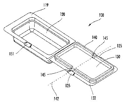
shows a perspective view of a package assembly 100 according to one embodiment
of the present invention. As shown the package assembly 100 of the depicted
embodiment may generally comprise a container portion 110 defining an opening
120 and including at least two opposing sides 112, 114. The package assembly
100 may further comprise a cover portion 130 configured to cooperate with the
container portion 110 to selectively close the opening 120 defined by the
container
portion 110.
Furthermore, in order to effectively close the opening 120 defined by the
container portion 110, the cover portion 130 may comprise a reinforcing ridge
portion 140 operably engaged about a perimeter of the cover portion 130 and
configured to be capable of engaging an inner periphery of the opening 120, in
an
interference fit, so as to selectively close the opening 120, such that the
cover
portion 130 is not easily disengaged from the container portion 110 without
the
application of a compressive force 200, as described herein. Furthermore, the
reinforcing ridge portion 140 may also define a pair of flexure channels 145
on
opposing sides 131, 133 of the cover portion 130. Furthermore,. the flexure
channels 145 may cooperate to define a flexure axis 142 extending
substantially
perpendicularly to the opposing sides 131, 133 of the cover portion 130
defining
the flexure channels 145 such that the flexure axis 142 is substantially
parallel to
the opposing sides 112, 114 of the container portion 110. It should be noted
that in
various embodiments, only a portion of the cover portion 130 and the container
portion 110 may cooperate to hold the portions in a closed position. Moreover,
an
interference fit need not be required to hold the cover portion 130 in a
closed
position over the opening 120 of the container portion 110. Package assemblies
of
various embodiments of the present invention may be configured so that at
least
one of first or second portions flex outwardly about a flexure access in
response to
a compressive force. In such a manner, the first and second portions may
separate,
at least partially, in response to the compressive force, thus releasing at
least a
-8-
CA 02656641 2008-12-30
WO 2008/006056 PCT/US2007/072935
portion of a particulate aliquot contained within the package assembly. Thus,
for
example, package assemblies of other embodiments may comprise independent
first and second portions. Additionally, an adhesive or heat sealing material
may
be used to hold the first and second portions (or a portion of the first and
second
portions) in a closed position, wherein the adhesive or sealing material is
designed
to fail when the package assembly is subjected to a compressive force.
According to various embodiments of the present invention, the container
portion 110, the cover portion 130, and the opening 120 defined by the
container
portion may be formed into a variety of different shapes. For example, in some
embodiments, as shown generally in FIGS. 1-3, the various components of the
package assembly may be formed in a substantially rectangular shape. In other
embodiments the various components (such as the container portion 110, cover
portion 130, and reinforcing ridge portion 140) may be formed to have a
variety of
outer shapes, including but not limited to: polygonal shapes (including, but
not
limited to rectangles, triangles, hexagons); circular; oval; semi-circular;
and
combinations of such shapes.
As shown in FIG. 2a, the flexure channels 145 defined in the reinforcing
ridge portion 140 of the cover portion 130 may have a substantially half-
circular
cross section. According to other embodiments, the flexure channels 145 may
also
define various other cross-sectional shapes that may be tailored to define a
flexure
axis 142 (see FIG. 1, for example) extending substantially perpendicularly to
the
opposing sides 131, 133 of the cover portion 130. For example, the flexure
channels 145 may, in some alternative embodiments, define cross-sectional
shapes
that may include, but are not limited to: rectangular; oval; circular;
triangular; and
combinations of such cross-sectional shapes. The shape of the cross-section of
the
flexure channel 145 may thus be tailored to suit the material used to form the
cover
portion 130 and/or the reinforcing ridge portion 140 so as to define a
distinct
flexure axis 142 across a width of the cover portion 130 such that the cover
portion
flexes outwardly from the container portion 110 about the flexure axis 142
defined
by the opposing flexure channels 145 (see, for example, FIG. 1 and FIG. 2a
(showing the flexing action of the cover portion 130 about the flexure axis
142 in
response to a compressive force 200 applied to the container portion 110)).
Thus, as shown generally in FIG. 2a, the cover portion 130 may be
configured to flex outwardly from the container portion 110 about the flexure
axis
-9-
CA 02656641 2008-12-30
WO 2008/006056 PCT/US2007/072935
142 (see FIG. 1), when a compressive force 200 is applied to the at least two
opposing sides 112, 114 of the container portion 110. The compressive force
200
may thus initiate the disengagement of the reinforcing ridge portion 140 from
the
inner periphery of the opening 120 so that the cover portion 130 disengages
from
the container portion 110. As shown generally in FIGS. 2a and 2b, the package
assembly 100 of the present invention may, in some exemplary embodiments, be
inverted such that the cover portion 130 may drop away from the container
portion
110 after the reinforcing ridge portion 140 has been disengaged from the inner
periphery of the opening 120 (due, for example, to a compressive force 200
applied
to the opposing sides 112, 114 of the container portion 100 as shown generally
in
FIG. 2a). As shown generally in FIG. 2b, the package assembly 100 may thus be
used to disperse a plurality of particles 300 (such as a seed sample aliquot)
that
have been segregated and contained within the container portion 110 of the
package assembly 100 of the present invention. As described generally above,
the
package assembly 100 embodiments of the present invention may be
advantageously opened by the simple application of a compressive force 200 on
the opposing sides 112, 114 of the container portion 110 of the package
assembly
100 while suspending the package assembly 100 in an inverted position (as
shown
generally in FIG. 2a). It should be noted that in other embodiments, the
application of a compressive force may comprise applying a force to one of
opposing sides 112, 114 while the other side is supported, so as to effect a
compressive force on the package assembly 100.
According to some other embodiments, the package assembly 100 may be
positioned in a substantially upright position (i.e. with the cover portion
130
positioned above the container portion 11.0) during the application of a
compressive force 200 to the opposing sides 112, 114 of the container portion.
As
described generally above, the cover portion 130 may thus flex outwardly from
the
container portion 110 about the flexure axis 142 and disengage from the
interference fit with an inner periphery of the opening 120 defined in the
container
portion 110. In such embodiments, a hinge portion 150 (as discussed further
below) disposed between the container portion 110 and the cover portion 130
may
be biased to expand so as to urge the cover portion 130 away from the
container
portion 110 once the reinforcing ridge portion 140 of the cover portion 130
has
-10-
CA 02656641 2008-12-30
WO 2008/006056 PCT/US2007/072935
been initially disengaged from the container portion 110 by the application of
the
compressive force 200.
As shown generally in FIGS. 2a and 2b, the package assembly 100 may
further comprise a hinge portion 150 operably engaged between an edge of the
cover portion 130 and one of the at least two opposing sides 112, 114 of the
container portion 110 such that the cover portion 130 and the container
portion 110
may form a substantially unitary package assembly 100 even when the cover
portion 130 (and the reinforcing ridge portion 140 extending therefrom) is
disengaged from the inner periphery of the opening 120 defined in the
container
portion 110 (as shown generally in FIG. 2b). In some embodiments of the
present
invention, the hinge portion 150 may be integrally formed with one or both of
the
container portion 110 and the cover portion 130 to form a unitary package
assembly 100. According to some alternative embodiments, the hinge portion 150
may also be operably engaged with one or both of the container portion 110 and
the cover portion 130 using an adhesive material in order to form the package
assembly 100 (such as that shown, for example, in FIG. 1). As described
generally above, the hinge portion 150 may be formed with a bias towards the
"open" position (as shown generally in FIG. 2b) such that the hinge portion
150
may urge the cover portion 130 generally away from the container portion 110
once the compressive force 200 has caused the initial disengagement of the
reinforcing ridge portion 140 from an inner periphery of the opening 120
defined
in the container portion 110.
In some additional embodiments of the present invention, as shown
generally in FIG. 1 and FIG. 3 the package assembly 100 may further comprise a
shelf portion including a flange 116 extending substantially perpendicular
from an
outer periphery of the opening 120 and a wall portion 118 extending
substantially
perpendicular from the flange 116. The shelf portion defined by the flange 116
and wall portion 118 may thus provide a seating area for the reinforcing ridge
portion 140 of the cover portion 130 as the cover portion 130 is engaged with
the
container portion 110 to close the opening 120 defined therein. For example,
as
shown in the exemplary cross-sectional view of one embodiment of the package
assembly in FIG. 3, the reinforcing ridge 140 may be configured to engage the
shelf portion (comprising the flange 116 and wall portion 118, for example) so
as
to selectively close the opening 120 defined in the container portion. Thus,
the
-11-
CA 02656641 2008-12-30
WO 2008/006056 PCT/US2007/072935
shelf portion defined by the flange 116 and wall portion 118 may, in some
embodiments, prevent the cover portion 130 from encroaching upon the volume of
the container portion 110 and potentially damaging and/or crushing the
plurality of
particles 300 (such as a seed sample aliquot) contained therein.
Furthermore, as shown generally in FIGS. 1 and 3, the package assembly
100 may also comprise a pair of complementary flange portions 119, 132
extending outward from an outer periphery of the opening 120 and the
reinforcing
ridge portion 140 of the cover portion 130, respectively. For example, as
shown in
FIG. 3, the package assembly 100 may further comprise a first flange portion
119
extending substantially perpendicular from at outer periphery of the opening
120
(which may, in some embodiments, be defined by an edge of the wall portion 118
of the shelf portion), and a second flange portion 132 extending substantially
outward from the reinforcing ridge 140 such that when the cover portion 130
closes the opening 120 defined by the container portion 110, the first flange
portion 119 is substantially adjacent and parallel to the second flange
portion 132.
Furthermore, as shown generally in FIGS. 1 and 2a, the second flange portion
132
may define a pair of opposing concave portions 135 substantially coaxial with
the
flexure axis 142. According to such embodiments, the pair of opposing concave
portions 135 may form a corresponding pair of apertures between the first and
second flange portions 119, 132 when the cover portion 130 closes the opening
120 defined by the container portion 110. For example, in some such
embodiments, the pair of apertures defined by the opposing concave portions
135
formed in the second flange portion 132 may be adapted to be capable of
receiving
an opening tool for encouraging the cover portion 130 to flex outwardly from
the
container portion 110 about the flexure axis 142 (see generally FIG. 2a) so
that the
cover portion 130 disengages from the container portion 110. Thus, such
opposing
concave portions 135 defined by the second flange portion 132 may serve to
define
a corresponding pair of apertures between the flange portions 119, 132 so that
an
opening tool (such as, for example, a screwdriver, knife, or other narrow-
bladed
implement) and/or a fingertip may be inserted into the aperture located at or
near
the flexure axis 142 so as to urge the cover portion 130 out of its
interference fit
with the container portion 110. One skilled in the art will also appreciate
that the
apertures defined by the opposing concave portions 135 defined by the second
flange portion 132 may also define a corresponding pair of apertures for
receiving
-12-
CA 02656641 2008-12-30
WO 2008/006056 PCT/US2007/072935
an automated tool that may serve to accompany the application of the
compressive
force 200 (see FIG. 2a, for example) in order to urge the cover portion 130
outwardly from the container portion 110 about the flexure axis 142. The
compressive force 200 (coupled with the application of an automated opening
tool
at the location of the opposing ridges 135) may thus disengage the reinforcing
ridge portion 140 from the inner periphery of the opening 120 so that the
cover
portion 130 disengages from the container portion 110. It should be noted that
in
other embodiments, one or more concave portions may be located anywhere on the
package assembly wherein the concave portion(s) are configured to receive an
opening tool for encouraging the first and second portions to separate.
FIG. 4 shows another exemplary embodiment of a package assembly 100
similar to that shown and described with respect to FIGS. 1-3. As above, the
package assembly 100 includes a pair of opposing concave portions 135 defined
by
the second flange portion 132 of the cover portion 130, however the depicted
embodiment also includes at least one corresponding concave portion 151
defined
by the first flange portion 119. The corresponding concave portion 151 is
configured such that when the cover portion 130 is engaged with the container
portion 110, the corresponding concave portion 151 substantially aligns with
one
of the opposing concave portions 135 defined by the second flange portion 132.
In
such a manner, the aligned corresponding concave portion 151 and concave
portion 135 form a larger aperture between the first and second flange
portions
119, 132 when the cover portion 130 closes the opening 120 defined by the
container portion 110. As a result, the aperture formed by the corresponding
concave portion 151 and the concave portion 135 creates a larger target for
receiving an opening tool for encouraging the cover portion 130 to flex
outwardly
from the container portion 110 about the flexure axis 142 so that the cover
portion
130 disengages from the container portion 110. In various embodiments, this
may
increase opening success for packaging assemblies with dimensional
variability. It
should be noted that although one corresponding concave portion 151 is shown
in
the drawing, in other embodiments an opposing concave portion may be included
so as to substantially align with the other of the opposing concave portions
135
when the cover portion 130 closes the opening 120 defined by the container
portion 110.
-13-
CA 02656641 2008-12-30
WO 2008/006056 PCT/US2007/072935
Another exemplary embodiment of the present invention is shown in FIG.
5. This embodiment is similar to that described with respect to FIGS. 1-3,
however in this embodiment, at least one notch portion 153 is defined by the
first
flange portion 119. The notch portion 153 is configured to allow a disengaging
device to exert a force against the second flange 132 through the notch
portion 153.
In such a manner, the disengaging device may further facilitate disengaging
the
cover portion 130 from the container portion 110. In various embodiments, a
disengaging device may be any device, tool, and/or mechanism configured to
exert
a force through the notch portion 153 against the second flange 132. The
disengaging device may comprise, but is not limited to, a pneumatically
operated
pin. It should be noted that in some embodiments, a disengaging device may be
responsible for facilitating disengaging the cover portion 130 from the
container
portion 110 without the use of an opening device. As such, in various
embodiments a disengaging device may be used alone, or in combination with an
opening tool received in one or both of the pair of apertures defined by the
opposing concave portions 135. As a result, in various embodiments, this may
also
increase opening success for packaging assemblies with dimensional
variability. It
should be noted that although the notch portion 153 shown in the depicted
embodiment is generally rectangular in shape, one skilled in the art will
recognize
that a notch portion in accordance with the present invention may take many
other
shapes, including, but not limited to, a half circular shape, a half oval
shape, a
triangular shape, a circular shape, an oval shape, and combinations thereof.
FIG. 6 shows still another exemplary embodiment of the present invention.
The depicted embodiment includes both a corresponding concave portion 151 and
a notch portion 153 defined by the first flange portion 119. As described
above,
the corresponding concave portion 151 is configured such that when the cover
portion 130 is engaged with the container portion 110, the corresponding
concave
portion 151 substantially aligns with one of the opposing concave portions 135
defined by the second flange portion 132. The notch portion 153 is configured
to
allow one or more disengaging devices to exert a force against the second
flange
132 through the notch portion 153. In such a manner, compressive forces 200
may
thus initiate the disengagement of the reinforcing ridge portion 140 from the
inner
periphery of the opening 120 so that the cover portion 130 disengages from the
container portion 110. Additionally, an opening tool may be received by an
-14-
CA 02656641 2008-12-30
WO 2008/006056 PCT/US2007/072935
aperture defined by the concave portion 135 and the corresponding concave
portion 151 for encouraging the cover portion 130 to flex outwardly from the
container portion 110 about the flexure axis 142 (see generally FIG. 2a).
Simultaneously, a disengaging device may exert a force against the second
flange
132 through the notch portion 153, to further encourage disengagement of the
cover portion 130 from the container portion 110. As a result, in various
embodiments, this may further increase opening success for packaging
assemblies
with dimensional variability.
As described generally above, according to some embodiments of the
package assembly 100 of the present invention, the container portion 110, the
cover portion 130, the reinforcing ridge 140, and the hinge portion 150 may be
substantially integrally formed such that the package assembly may be
configured
as a substantially one-piece assembly. Various manufacturing processes may be
used to generate such single-piece package assembly 100 embodiments. For
example, integrally-formed package assemblies 100 may be formed using
processes including, but not limited to: thermoforming; vacuum forming; blow
molding; injection molding; casting; and combinations of such processes. In
addition, and as generally described above, the various container portions
110,
cover portions 130, and hinge portions 150 of the package assembly 100 may
also,
in some embodiments, be molded and/or formed separately and operably engaged
in subsequent processes that may include, but are not limited to: joining
processes
involving the application of a heat source, adhesive application processes,
and/or
mechanical joining processes (such as, for example stapling).
According to some embodiments of package assembly 100 of the present
invention, the various components (including the container portion 110, cover
portion 130, reinforcing ridge portion 140, and hinge portion 150, for
example)
may be composed of one or more different material types. For example, the
container portion 110 of the package assembly 100 may be formed of a somewhat
flexible, resilient, and/or self-supporting material so as to be capable of
responding
to a compressive force 200 (exerted, for example, on opposing sides 112, 114
of
the container portion 110) and deforming slightly so as to cause the cover
portion
130 to flex outwardly about the flexure axis 142 (as shown in an exemplary
side
view of FIG. 2a). For example, the package assembly 100 may comprise a variety
of different polymer compounds that may include, but are not limited to:
polyester;
-15-
CA 02656641 2008-12-30
WO 2008/006056 PCT/US2007/072935
polylactic acid (PLA); polypropylene; polyethylene terephthalate (PETE);
polyvinyl chloride (PVC); high-density polyethylene (HDPE); low-density
polyethylene (LDPE); and combinations of such materials.
Many modifications and other embodiments of the invention will come to
mind to one skilled in the art to which this invention pertains having the
benefit of
the teachings presented in the foregoing descriptions and the associated
drawings.
Therefore, it is to be understood that the invention is not to be limited to
the
specific embodiments disclosed and that modifications and other embodiments
are
intended to be included within the scope of the appended claims. Although
specific terms are employed herein, they are used in a generic and descriptive
sense only and not for purposes of limitation.
-16-