Note: Descriptions are shown in the official language in which they were submitted.
CA 02657079 2014-05-12
, 68188-256
- 1 -
Description
Modular drilling tool and method for the production
thereof
The invention relates to a modular drilling tool. The
invention furthermore relates to a method for producing
such a drilling tool.
Modular drilling tools are known in a variety of
embodiments, which differ, for example, in their
holding of separately realized cutting units. For
example, soldered-in hard-metal cutting tips or
complete drill bits are used as cutting units. There
are known, moreover, changeable cutting units, such as
reversible cutting plates, which are held on the
carrier body of the drilling tool by means of screws,
or such as cassettes, comprising reversible cutting
plates, which are connected to the carrier body through
positive holding. There are additionally known
exchangeable drill bits, which are fastened to the
carrier body, for example, by means of screws or
through clamping or through positive fit. Common
to
all of these modular drilling tools is the division
into the cutting unit and the carrier body. The
carrier body has a front region, comprising chip
grooves, and a shank region, for receiving the drilling
tool into a clamping device of a machine tool.
A drilling tool is
known from DE 195 22 836 Al. In the case of this tool,
realized as a drilling tool having reversible cutting
plates, an inner chip groove and an outer chip groove
are shaped in such a way that they merge into one
another in the middle to rear region of the tool. In
the case of this tool, the chip groove has stiffening
beads on both walls.
ak 02657079 2014-05-12
. 68188-256
- 2 -
Fluctuations of the parameters in the drilling process result
in the formation of differing chip shapes. In addition to the
wanted fragmental chip pieces, unwanted helical chips and
helical fragmental chips can also be produced. These chip
portions, when being removed from the cutting edge of the
drilling tool via the chip groove, continually cause contact
with the wall of the bore, resulting in scores that impair the
surface quality of the bore produced.
Moreover, a continual occurrence is that, at the run-out edge,
chips become jammed between the wall of the bore and the rear
of the drill, and thereby cause increased torsional loading of
the drill body. In this situation, there is also an increased
thermal loading of the drill, since the heat produced during
cutting is also taken away from the base of the bore with the
chips. In extreme cases, such a jammed-in chip thereby becomes
welded to the wall of the bore.
An embodiment of the present invention is based on the object
of specifying a modular drilling tool, and a method for the
production thereof, having a chip groove that is particularly
suitable in respect of the conveyance of chips.
According to an embodiment of the invention, there is provided
a modular drilling tool, comprising a carrier body and a
cutting unit that can be fastened thereto, the carrier body
extending along a carrier body longitudinal axis, being
realized substantially as a circular cylinder having a carrier
body radius, and having a chip groove and a run-out edge that
extends along the chip groove, wherein the chip groove extends
towards the run-out edge in a convexly curved manner and a wall
portion of the chip groove that is opposite the run-out edge
ak 02657079 2014-05-12
. 68188-256
- 2a -
runs out rectilinearly such that - viewed in a cross sectional
view perpendicular to the carrier body longitudinal axis - the
chip groove is delimited by a J-shaped chip groove wall and a
concave fillet is formed, such that an acute advance angle is
realized between a chip groove tangent to the run-out edge and
a radial that, at a tangent point, is tangential to the groove
base in the region of the concave fillet; and wherein the
carrier body has a front region extending in the direction of
the carrier body longitudinal axis and has a run-out region
adjoining the front region, the advance angle decreasing
continuously in the direction of the carrier body longitudinal
axis in the run-out region.
According to another embodiment of the invention, the drilling
tool is realized in a modular manner, and has a substantially
circular-cylindrical carrier body having a carrier body radius,
and has a holder, realized on the carrier body, for the cutting
unit. The carrier body comprises a run-out edge extending along
a chip groove. The chip groove extends towards the run-out edge
in a convexly curved manner such that - viewed in a cross-
sectional view perpendicular to the carrier body longitudinal
axis - a concave fillet is formed,
CA 02657079 2009-01-05
- 3 -
and an acute advance angle is realized between a chip
groove tangent to the run-out edge and a radial that,
at a tangent point, is tangential to the groove base in
the region of the concave fillet. The delimiting wall
of the chip groove in this case has a J-shaped contour,
i.e. is composed approximately of a semicircular arc,
adjoining one side of which there is a rectilinear wall
portion. Overall,
therefore, the chip groove has an
asymmetric conformation, to the extent that the chip
groove has a rectilinear wall portion on its one side
and has a solely curved wall portion on its other side.
The curved wall portion realizes the concave fillet and
the acute advance angle. The
rectilinearly extending
wall portion is thus opposite the run-out edge in the
direction of rotation, and extends out rectilinearly in
the direction of the circumferential surface of the
carrier body, said circumferential surface constituting
a rear of the drill. This enables the chip groove to
be produced by simply being milled into the carrier
body, along this rectilinear run-out.
In respect of production technology, therefore, the J-
shaped form is achieved in that the grooves are made by
means of a milling cutter, for example a ball-ended
milling cutter or a milling disc. The milling
cutter
is advanced is, not in the radial direction, but rather
tangentially to the blank to be machined. Tangential
advancing in this case is understood to mean that the
center of the milling cutter is not applied in the
radial direction to the carrier body longitudinal axis,
but rather that the center of the milling cutter is
placed on the blank such that it is parallel to, but at
a distance from, a radial.
Chip groove tangent in this case is understood to be
the tangent to the chip groove wall at the run-out
corner at which the chip groove wall meets the run-out
edge, which tangent is oriented perpendicularly in
relation to the carrier body longitudinal axis. The
CA 02657079 2009-01-05
- 4 -
radial likewise extends perpendicularly in relation to
the carrier body axis, and is tangential to the chip
groove wall in its lowest point, which here is denoted
as the tangent point.
The resultant sickle-shaped form of the chip cavity
constituted by the chip groove results in an improved
chip guidance, since, owing to the acute advance angle,
there is realized a kind of wedge that, as it were,
scrapes the chip from the wall of the bore. At the
same time, owing to the convex curvature and the
concave fillet constituted thereby, the chip is guided
securely into the chip groove, and held there. The
risk of a chip becoming jammed between the drilling
tool and the wall of the bore is therefore reduced.
The curvature of the chip groove is also instrumental
in the shaping of the chip, such that the latter can be
taken away easily and reliably in the chip groove. At
the same time, owing to the J-shaped form, the chip is
held reliably in the chip cavity.
According to an expedient development, the advance
angle is in the range of between 40 and 70 . A
particularly distinct and secure chip guidance within
the chip groove is thereby achieved.
Advantageously, in the region of the concave fillet the
chip groove is realized along a circular path having a
radius of curvature. Such a circular path is produced,
in particular, by a milling cutter whose radius
corresponds substantially to the radius of curvature of
the concave fillet. For reasons
of production
technology, the radius of the concave fillet is
somewhat greater than the radius of the milling cutter.
The shape of the chip groove can thus be easily
produced through the selection of a suitable tool, and
the radius realized at this wall results in an improved
shaping of the chips to be taken away.
CA 02657079 2009-01-05
- 5 -
In an advantageous development, the chip groove has a
diameter of between 0.4 and 0.6 times the carrier body
radius. This dimensioning has proved advantageous, the
remaining cross-section of the carrier body being, at
the same time, suitable for absorbing the occurring
forces and moments.
Preferably, the concave fillet has a fillet width of
between 0.6 and 1 times the radius, and thus between
0.3 and 0.5 times the diameter, of the milling cutter
used. Advantageously, at the same time the concave
fillet has a fillet depth in the range of 0.3 to 0.8
times the radius of curvature. The fillet
width in
this case is defined by the distance between the
tangent point of the groove base and the projection of
the run-out edge to the radial. The fillet
depth in
this case is the distance of the radial through the
tangent point from the run-out edge. A concave fillet
shaped thus guides the chips, over the entire course,
particularly well in the chip groove cross-section.
Preferably, the carrier body has a front region
extending in the carrier body longitudinal direction,
and has a run-out region adjoining this front region.
The run-out region serves to eject the chip material.
In the run-out region, the advance angle decreases in
the carrier body longitudinal direction, in particular
continuously and progressively, towards the carrier
body shank, resulting in a likewise continuously
decreasing concave fillet. Owing to this
decrease in
the concave fillet, the chip material can run freely
out of the groove. Preferably in this case the advance
angle decreases in the carrier body longitudinal
direction, from the end of the front region, beyond the
run-out region, to at least 00.
Owing to the greatness of their length relative to
their diameter, and to the cross-section being reduced
by the chip groove, drilling tools are liable to
ak 02657079 2014-05-12
' . 68188-256
- 6 -
deformations, especially deflection, as a result of the
forward-feed forces during the drilling operation. The
vibrations resulting therefrom reduce the quality of the bore.
In a preferred embodiment, therefore, the run-out region has a
length of between 1.0 and 2.0 times the radius of curvature.
This length ensures a free run-out of the chip material without
excessive elongation of the carrier body.
In an expedient development, in a middle partial region of the
run-out region the chip groove has opposing wall regions that
extend parallelwise in the initial region and are connected by
a semicircular path. This groove shape can be easily produced
by the milling cutter used for the front region.
According to another embodiment of the invention, there is
provided a method for producing a modular drilling tool, which
has a carrier body realized substantially as a circular
cylinder extending along a carrier body longitudinal axis and
having a carrier body radius, and which has a cutting unit that
can be fastened to this carrier body, and has a chip groove and
a run-out edge that extends along the chip groove, the chip
groove being machined with the aid of a milling cutter such
that - viewed in a cross-sectional view perpendicular to the
carrier body longitudinal axis - the chip groove is realized to
be J-shaped, such that it extends towards the run-out edge in a
convexly curved manner and a concave fillet is formed, such
that an acute advance angle is realized between a chip groove
tangent to the run-out edge and a radial that, at a tangent
point, is tangential to the groove base in the region of the
concave fillet, wherein the milling cutter being swiveled-in in
a run-out region of the chip groove in such a way that the
CA 02657079 2014-05-12
= 68188-256
- 6a -
advance angle decreases in the direction of the carrier body
longitudinal axis.
The advantages and preferred developments stated in respect of
the drilling tool are also to be assigned analogously to the
method.
For the purpose of producing the drilling tool, provision is
made in this case whereby the chip groove is machined by means
of a milling cutter in such a way that the chip groove, viewed
in a cross-sectional view perpendicular to the carrier body
longitudinal axis, extends convexly towards the run-out edge,
and a concave fillet is formed, in such a way that an acute
advance angle is realized between a chip groove tangent to the
run-out edge and a radial that, at a tangent point, is
tangential to the groove base in the region of the concave
fillet. Such a method is suitable for producing the chip groove
in a continuous operation.
In an expedient enhancement, the chip groove is machined in a
continuous operation, following the milling in the front
region, in a run-out region adjoining the front region. In this
case the milling
CA 02657079 2009-01-05
- 7 -
cutter is preferably swiveled in such a way that the
advance angle is reduced, in particular, to 00. This
measure results in the sickle-shaped form of the chip
cavity, constituted by the concave fillet, undergoing
transition to a straight run-out. That is to
say, at
least in the end region of the run-out region, the chip
groove wall extends out rectilinearly, such that the
chip can emerge easily from the chip groove. In this
case, the milling cutter is swiveled appropriately in a
simple manner. There is then no need for tool changing
for alteration of the cross-sectional geometry, such
that a rapid, inexpensive realization of the chip
groove in only one working step is rendered possible.
The special realization of the run-out region is also
possible, in principle, independently of the form of
the chip groove with the concave fillet, and is
independently inventive in its own right. A run-out
region realized thus can also be used in the case of
conventional tools. Owing to the
special form of the
run-out region, trouble-free emergence of chips from
the chip groove is also achieved in the case of these
tools.
An exemplary embodiment of the invention is explained
more fully in the following with reference to a
drawing, wherein, in schematic representations,
respectively:
Fig. 1 shows a perspective representation of a carrier
body of a modular drilling tool,
Fig. 2 shows a side view of the carrier body according
to Fig. 1,
Fig. 3 shows a cross-section perpendicular to the
carrier body longitudinal axis, along the
section line in Fig. 2,
Fig. 4 shows a top view of a section perpendicular to
the carrier body longitudinal axis, along the
section line IV-IV in Fig. 2, and
CA 02657079 2009-01-05
- 8 -
Fig. 5 for the purpose of explaining the method for
milling the chip groove, shows a highly
schematic front view of the carrier body with
an indicated milling head in differing milling
positions.
Parts that correspond to one another are denoted by the
same references in all figures.
Fig. 1 shows a perspective view of a carrier body of a
modular drilling tool 1, without a cutting unit. The
carrier body 2 is divided into a front region 3 and a
shank region 4. The two
regions are separated by a
shoulder 5, which constitutes a bearing-contact collar.
In the exemplary embodiment, the front region 3 has two
chip grooves 6, which extend helically, diametrically
opposite one another, in the front region 3. Viewed in
the direction of rotation D of the drill, the chip
groove 6 is in each case adjoined at the end by a run-
out edge 8, which likewise extends helically,
corresponding to the chip groove 6. Provided
towards
the shank region 4 is a run-out region 10, in which the
chip groove 6 runs out of the carrier body 2, along the
shoulder 5. The carrier
body 2 additionally has a
coolant bore 12 that corresponds, respectively, to each
of the chip grooves 6, the openings of which bores are
arranged on the end face 11 of the carrier body 2. In
the exemplary embodiment, two plate seats 14, for
receiving reversible cutting plates 16 (cf. Fig. 2),
not represented in Fig. 1, are realized in the front
end region of the carrier body 2.
The reversible cutting plates 16 each constitute a
cutting unit of the modular drilling tool 1.
Exchangeable drill bits, in particular, can also be
provided as cutting units, as an alternative to
reversible cutting plates 16. The modular
structure
offers the inexpensive possibility of using for the
cutting unit highly specialized materials that
CA 02657079 2009-01-05
- 9 -
withstand the large loads during chip-removing
machining, and at the same time of using other
appropriate, and less expensive, materials for the
carrier body. Owing to
the exchangeability of the
cutting units, it is also the case that only the
cutting units need be exchanged when cutting edges have
become worn.
Fig. 2 shows a side view of the drilling tool 1.
Represented on the carrier body 2 are two reversible
cutting plates 16, which are fastened, radially offset
in relation to one another, in the respective plate
seat 14. The
reversible cutting plates 16 project
beyond the end face 11. The radially inner reversible
cutting plate 16 extends beyond the carrier body
longitudinal axis Z and at the same time overlaps the
outer reversible cutting plate 16 in the radial
direction, as a result of which both reversible cutting
plates 16 have an overlapping working region. If
necessary, the radially inner and radially outer
reversible cutting plates 16 differ in their
realization.
The length of the drilling tool 1 as a whole is given
by a clamping length L2 of the shank region 4 and an
effective projection length Ll. The run-out region 10
adjoining the front region 3 has the length L3. In
this case, the active drilling length of the front
region 3 corresponds to a bore depth for which the
drilling tool is intended. This bore depth is usually
specified in multiples of the carrier body diameter.
The active length of the front region corresponds
substantially to the difference between the effective
projection length Ll and the length L3 of the run-out
region 10.
Whereas, over the length of the front region 3, the
chip groove 6 has a chip groove geometry that remains
substantially constant, this geometry varies
CA 02657079 2009-01-05
- 10 -
continuously in the course of the run-out region 10.
Substantially constant geometry in this case is
understood to mean that the basic geometry, explained
in the following with reference to Fig. 3, is
maintained apart from possible variations of the
individual dimensions, for example because of a core
tapering in the longitudinal direction of the drilling
tool 1. The chip
groove 6 in the front region 3 in
this case is realized for good chip shaping and chip
discharge, in particular in such a way that the chip is
held securely in the chip groove 6 and the chip is
prevented from becoming jammed between a wall of the
bore and the rear of the drill. In the run-out region
10, by contrast, the chip groove 6 is realized such
that the chip can emerge easily from the chip groove 6.
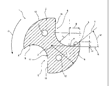
Fig. 3 shows a cross-sectional surface along the
section line according to Fig. 2. The two
coolant bores 12 are arranged within the carrier body
2, which has a carrier body radius Tr. The chip groove
6 is delimited by an approximately J-shaped chip groove
wall 17. The latter
has a wall portion that has the
shape of a circular arc and has a radius r. This wall
portion in the shape of a circular arc runs out, on the
one side, to the rear of the drill, and adjoins the
run-out edge 8.
The chip groove 6 thereby constitutes a concave fillet
18 towards the run-out edge 8, and has a sickle-shaped
course in the region of the concave fillet 18. The
sickle tip is constituted by the run-out edge 8. An
advance angle W is realized in this case between a chip
groove tangent T and a radial R. The chip
groove
tangent T is the tangent of the circular-arc-shaped
wall portion, in the run-out point of the wall portion,
to the run-out edge 8. The radial R is constituted by
a straight line that extends through the middle point
(carrier body longitudinal axis Z) and that is
tangential to the groove base in the region of the
CA 02657079 2009-01-05
- 11 -
concave fillet. The point of contact of the radial R
in the region of the groove base is termed the tangent
point P. The concave
fillet 18 has a fillet depth H
and a fillet width B. The fillet depth H is defined as
the distance of the radial R from the run-out edge 8,
i.e. the fillet depth H - viewed in a cross-sectional
view - corresponds to the shortest distance between the
radial R and the run-out edge 8, thus to the corner
point between the chip groove wall and the rear of the
drill. The fillet width B in this case is defined by
the distance between the radial R tangential to the
groove base and a projection of the run-out edge to the
radial R. The fillet width B is therefore the distance
between the tangent point P and a vertical to the
radial R extending through the corner point (run-out
edge 8) between the chip groove wall and the rear of
the drill.
The chip groove wall runs out acutely towards the run-
out edge 8, such that an approximately wedge-shaped
wall region is realized. The advance
angle W in this
case lies in a range of between approximately 40 and
70 . This very acute form reliably reduces the risk of
a chip becoming jammed between a bore wall and the rear
of the drill. Rather, owing
to the wedge-shaped or
sickle-shaped form, the chip is scraped from the bore
wall and caught in the sickle-shaped concave fillet 18.
At the same time, a good chip shaping effect is
achieved by the curvature of the chip groove wall
adjoining the run-out edge 8. For this
purpose, the
concave fillet 18 has a radius of curvature that, in
particular, is in the range of between 0.4 and 0.6
times the carrier body radius Tr. In order to hold the
chip securely and reliably in the chip groove 6, the
concave fillet width B is approximately in the range of
between 0.6 and 1.0 times the radius of curvature r.
At the same time, the concave fillet depth H is
approximately 0.3 to 0.8 times the radius of curvature
CA 02657079 2009-01-05
- 12 -
r. Overall, reliable chip removal is achieved through
this chip groove geometry.
The wall portion 19 of the chip groove 6 that is
opposite the run-out edge 8 in the direction of
rotation D is of little importance for the shaping and
the removal of chips, and in the exemplary embodiment
it is realized as a straight wall portion 19. Starting
from the run-out edge 8 above the circular-arc-shaped
wall portion in the region of the concave fillet 18,
the straight wall portion 19 extends as far as the rear
of the drill of the carrier body 2.
The chip groove geometry described here can be produced
in a simple and inexpensive manner, in particular in a
single-stage machining process, with the aid of a
milling cutter, in particular a ball-ended milling
cutter. There is no
need for resource-intensive
grinding processes or multiple application of a
machining tool. Rather, the
chip groove geometry is
determined substantially by the geometry of a milling
head 20 (cf. Fig. 5) of the ball-ended milling cutter.
The radius of curvature r of the concave fillet 18
therefore also corresponds substantially to the radius
of the ball-ended milling cutter.
The geometry of the chip groove 6 in the run-out region
10 can be seen from Fig. 4. Whereas the
basic
geometry, shown in Fig. 3, with the concave fillet 18
and the wall portion 19 running out rectilinearly
opposite the run-out edge 8, is constant beyond the
front region 3, the geometry varies over the run-out
region 10, in particular continuously.
The chip groove 6 is widened in the run-out region 10
and shaped out into the shoulder 5. In the run-
out
region 10, the fillet depth H decreases progressively,
until finally a rectilinear run-out is realized at the
end of the run-out region 10. The advance angle W is
CA 02657079 2009-01-05
- 13 -
therefore reduced to 00, and in certain instances can
also assume negative values. The chip is therefore no
longer held captive in the chip groove 6, but can
emerge from the latter without difficulty.
A concave fillet is now realized at the end of the run-
out region 10, on the opposite wall portion 19, and the
wall portion 19 extends along a curved line having the
radius of curvature r.
This geometry in the run-out region 10 is easily
produced through a defined swiveling of the milling
cutter. The milling
method for producing the chip
groove 6 is explained with reference to Fig. 5, in
which differing positions of the milling head 20 of a
ball-ended milling cutter, which are denoted by K1 -
K7, can be seen. The milling head 20 has a radius that
corresponds to the radius of curvature r. The carrier
body longitudinal axis Z constitutes the z direction,
and the plane of the drawing constitutes the x-y plane
of the indicated coordinate system.
For the production of the carrier body 2, a suitable
round material is turned to the required outer
dimension prior to the machining operation represented
in Fig. 5. In this
process, a shoulder 5 is produced
between the portion of the carrier body 2 intended as a
front region 3 and that intended as a shank region 4.
A thus produced semi-finished product for a carrier
body 2 is clamped-in by the shank region for the
purpose of milling the chip grooves 6, such that the
front region 3 to be produced can be machined. By
means of the milling head 20, milling into the carrier
body 2 is effected as described in the following, such
that a chip groove 6, having the required geometric
characteristics, is produced for each machining
operation.
CA 02657079 2009-01-05
- 14 -
For this purpose, starting from the end face 11 of the
carrier body 2, the milling head 20 is used to mill
into the latter, the distance of the milling cutter
longitudinal axis 24 from the carrier body longitudinal
axis Z being less than the carrier body radius Tr,
until the milling head 20 is tangential to a core
circle 22 of the carrier body 2. In this
position
(K1), the milling head 20 is moved, in a forward-feed
motion in the z direction, towards the shank region 4.
At the same time, the carrier body 2 is rotated in the
direction of rotation D, such that the helical chip
groove 6 is realized with a constant pitch and constant
advance angle W. The thus produced front region 3 of
the chip groove 6 has a length that corresponds to the
drilling depth intended for the drilling tool 1.
During the machining of the front region 3, the milling
head 20 assumes the relative position denoted by K1 in
Fig. 5 in respect of the carrier body 2.
The special movements of the milling head 20 or of the
carrier body 1 that are described here correspond to
the preferred and easily controlled sequence of
movements. The movements can also be executed,
however, through appropriate control of the
respectively other part. What is
crucial is the
relative positioning and movement of the milling head
20 in relation to the carrier body 2.
For the purpose of producing the chip groove 6 in the
run-out region 10, the milling head 20, with its
longitudinal axis 24 in the xy plane, is rotated about
Z in a previously calculated manner. The milling head
20 is therefore, as it were, rolled on the core circle
22. For this
purpose, the milling head 20 is rotated
about an axis of rotation 26 oriented parallelwise in
relation to the z direction. At the same time, a
forward feed is effected in the z direction and the
carrier body 2 is rotated further in the direction of
rotation D. The milling head 20 thereby moves through
. CA 02657079 2009-01-05
- 15 -
the positions K1 to K7. The depth of the chip groove 6
remains unchanged in this case.
Whereas, in the position Kl, the milling cutter
longitudinal axis 24 is oriented parallelwise in
relation to a center plane 28 of the carrier body 2, in
a middle region of the run-out region 10 it is oriented
perpendicularly relative to the center plane 28
(approximately position K4), and at the end of the run-
out region 10 it encloses an obtuse angle of
approximately 160 in relation to the center plane 28
(position K7). In the exemplary embodiment, the center
plane 28 is defined by a plane that is oriented
parallelwise in relation to the rectilinearly extending
wall portion 19 at the end of the front region 3 and at
the start of the run-out region 10.
From the position K7, the milling head 20 is moved, in
the direction of its longitudinal axis 24, out of the
carrier body 2. The machining operation is thereby
concluded.