Note: Descriptions are shown in the official language in which they were submitted.
CA 02657143 2009-03-04
LEVEL
BACKGROUND OF THE INVENTION
[001] This invention relates to a level.
FIELD OF THE INVENTION
[002] More specifically, the invention relates to a level which can be
converted
into a try square, and which incorporates a plumb indicator, a level
indicator, a slope
indicator and a laser pointer.
DESCRIPTION OF RELATED ART
[003] There are a great many patents and applications relating to levels or
combination levels and squares. Examples of such patents and applications
include
Canadian Patents Nos. 1,067,689, issued to George A. Johnson on December 11,
1979, 1,044,009, issued to Donald E. Wright on December 12, 1978, 1,230,224,
issued to Denis M. LaFreniere on December 15, 1987, 1,273,912, issued to
Harold
Zimmerman on September 11, 1990, 2,083,662, issued to Walter J. Hutchins et al
on
November 21, 2000 and 2,323,602, issued to Bruno Morin on December 30, 2008,
and Canadian Patent Applications Nos. 2,030,016, filed in the name of Jacques
Malouin on November 15, 1990 and 2,592,865, filed in the name of Ed Vaes on
January 26, 2006, and US Patents Nos. 2,277,071, issued to J.T. Cassell on
March
24, 1942, 2,692,440, issued to R.H. Walters on October 26, 1954, 5,001,838,
issued
to Mary E. Huxley et al on March 26, 1991, 5,025,567, issued to Robert E.
McWilliams et al on June 25, 1991, 5,459,935, issued to Eldon D. Paulson et al
on
October 24, 1995, 6,742,271, issued to Donald Jeffrey Rushing on June 1, 2004
and
7,299,560, issued to Jeffrey Diaz et al on November 27, 2007.
[004] In spite of the large number of patents and applications relating to
levels,
very few of the devices appear in the marketplace. The reason for this is that
many
1
CA 02657143 2009-03-04
of the levels are somewhat complicated and consequently expensive to
manufacture.
BRIEF SUMMARY OF THE INVENTION
[005] The present invention provides a level which is structurally relatively
simple, versatile and easy to manufacture.
[006] Accordingly, the invention relates to a level comprising:
an elongated, I-beam shaped body including a web, a top plate extending
outwardly from both sides of the top of the web and a bottom plate extending
outwardly from both sides of the bottom of the web;
an arm at one end of said body rotatable between a non-use position against
one side of the web between the top and bottom plates, and a use position in
which
the body and the arm define a square;
notches in the flanges at one end of the body for receiving said arm in the
use
position to releasably lock the arm in the use position;
a plumb indicator in said body;
a level indicator in said body; and
a slope indicator in said body.
BRIEF DESCRIPTION OF THE DRAWINGS
[007] The invention is described below in greater detail with reference to the
accompanying drawings, which illustrate a preferred embodiment of the
invention,
and wherein:
[008] Figure 1 is an isometric view of the level as viewed from above and one
end;
[009] Figure 2 is an isometric view of the level of Fig. I as seen from below
and
the other end thereof;
2
CA 02657143 2009-03-04
[0010] Figure 3 is a side view of the level of Figs. I and 2;
[0011] Figure 4 is an exploded, isometric view of one end of the level of
Figs. I
to 3;
[0012] Figure 5 is an isometric view of a slope indicator used in the level of
Figs.
1 to 3;
[0013] Figure 6 is a schematic, sectional view of the slope indicator of Fig.
5;
[0014] Figure 7 is a side view of one end of the level of Figs. 1 to 3
incorporating
a laser pointer; and
[0015] Figure 8 is an isometric view of another embodiment of the level.
DETAILED DESCRIPTION OF THE INVENTION
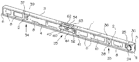
[0016] Referring to Figs. 1 to 3 of the drawings, the basic elements of the
level
include an elongated I-beam shaped body 1 defined by a planar web 2, top and
bottom plates or flanges 3 and 4, respectively, an open end 5 and an end plate
6.
The flanges 3 and 4 are integral with the web 2. The web 2, top plate 3 and
the
bottom plate 4 can be in the form of an extrusion. In order to reduce the
weight of the
level, a plurality of openings 8 are provided in the web 2. As shown in Fig.
2, the
bottom plate 4 of the level includes indicia 9, i.e. the bottom plate defines
a ruler,
which can be used as a straightedge.
[0017] An arm 10, which is preferably a ruler marked off in inches and
centimeters, is pivotally connected to a block 11 which is securely mounted
between
the top and bottom plates 3 and 4 at the open end 5 of the body 1. A cruciform-
shaped groove defined by intersecting vertical and horizontal grooves 13 and
14,
respectively is provided in one face 15 of the block for receiving a generally
T-
shaped nut 16. The nut 16 includes a rectangular end plate 18, which is
connected
to the inside surface of one end of the arm 10 by screws 19. An internally
threaded
3
CA 02657143 2009-03-04
sleeve 20 defines the stem of the nut 16. The sleeve 20 and a threaded hole 21
in
the arm 10 receive the threaded end 23 of a bolt 24. The bolt 24 has a large,
disc-
shaped head 25 with a knurled periphery 26 to facilitate rotation of the bolt.
A spring
28 on the sleeve 20 biases the nut 16 and the arm 10 outwardly, i.e. out of
the
grooves 13 and 14. When the bolt 24 is tightened, the nut 16 is drawn into one
of
the grooves 13 and 14, and consequently the arm 10 is drawn against the body
1.
When the arm 10 is in a non-use position (Figs. I and 2), i.e. when the level
is not
being used as a try square, the arm 10 is housed against the web 2 between the
top
and bottom plates 3 and 4, respectively of the level body 1. In order to move
the arm
to the try square position shown in phantom outline in Fig. 3, the bolt 24 is
loosened, and the spring 28 pushes the nut 16 and the arm 10 outwardly
permitting
rotation between the non-use and use positions. Notches 30 and 31 are provided
on
the arm side of the top and bottom plates 3 and 4 for receiving the arm 10 in
the use
position. Thus, the arm 10 can be rotated in either direction to a position
perpendicular to the body I of the level and, when the bolt 24 is again
tightened, the
arm is drawn into a locked, i.e. non-rotatable position in the notches 30 and
31.
[0018]The body 1 of the level contains three indicators, namely a plumb
indicator, a level indicator and a slope indicator which are indicated
generally at 33,
34 and 35, respectively. The plumb indicator 33 and the level indicator 34 are
off-
the-shelf items including square bodies 36 and 37, respectively mounted in
gaps in
the web 2 of the level body 1, and spirit level tubes 38 and 39 mounted in the
bodies
36 and 37, respectively. The plumb and level indicators 33 and 34,
respectively
perform in the same manner as in a conventional level.
[0019]The slope indicator 35 is mounted in a gap in the web 2 at the center of
the body 1 between the webs 2. The slope indicator includes a pair of plates
40 and
4
CA 02657143 2009-03-04
41 mounted at the inner ends of the web sections. A bifurcated end 43 of a
hollow,
cylindrical indicator body member 44 is connected to the plate 40 by a pin 45.
The
other bifurcated end 47 of the body member 44 overlaps the narrow, inner free
end
48 of the plate 41. The free end of one arm of the end 47 includes a
centerline 50
which, when the body member 44 is rotated becomes aligned with slope indicator
lines 51 on the plate 41. The body member is locked in one position using a
screw
52 which extends through one arm of the end 47 into engagement with the plate
41
to lock the body member in one position. A spirit level tube 54 is mounted in
a notch
55 in the top center of the body member 44. The tube 54 is illuminated by a
light in
the form of an LED 57 (Fig. 6) mounted in the body member 44 beneath the tube
54.
Power for the LED 57 is provided by a battery 59 mounted in the body member
44.
The LED 57 is switched on and off using a push button switch 60, which extends
outwardly through one side of the body member 44. An aperture 62 for viewing
the
level tube 54 is provided in a plate 63 defining the center portion of the top
plate 3.
[0020] Figure 7 of the drawings illustrates one end of another embodiment of
the
invention, which includes a laser pointer 65. The laser pointer 65 is an off-
the-shelf
item, the body 66 of which has been modified for mounting on the end 6 of the
level
body 1 between the top and bottom plates 3 and 4, respectively. The pointer 65
is
used in conjunction with one of the indicators 33 or 34 for projecting a true
vertical or
horizontal line on a planar surface.
[0021] A level primarily intended for use by plumbers is shown in Fig. 8 of
the
drawings. Wherever possible the same reference numerals have been used to
identify elements of Fig. 8 which are the same or similar to those of Figs. 1
to 7.
CA 02657143 2009-03-04
[0022] As in the case of the level of Figs. 1 to 3, the level of Fig. 8
includes an
elongated I-beam-shaped body 1 defined by a planar web 2, and top and bottom
flanges 3 and 4, respectively.
[0023] The top surface 68 of the flange 3 is a ruler marked off in inches and
centimeters. The bottom flange 4 incorporates a magnetic strip 69 for picking
up
small ferromagnetic articles or for attaching the level to an object such as a
stud,
pipe or duct formed of ferromagnetic material.
[0024] Tapered plastic caps 70 are provided on the ends of the body 1. The
caps 70 have bifurcated inner ends 71 overlapping the ends of the web 2.
Triangular
holes 72 in the caps 70 are used to hang the level on a hooK or other support
(not
shown). The web 2 contains a plumb indicator 33, a level indicator 34 and a
slop
indicator 35 which are the same as the corresponding elements in the level of
Figs. 1
to 3. One of the caps 70 can be replaced by a laser pointer (not shown).
6