Note: Descriptions are shown in the official language in which they were submitted.
CA 02657161 2009-03-04
1 Scanning System for 3D Mineralogy Modelling
2 FIELD OF THE INVENTION
3 This invention relates to scanning methods and systems. It has particular
application to open pit
4 mining in which material is removed successively from benches following
drilling and blasting,
however is not limited to that application.
6 BACKGROUND OF THE INVENTION
7 Conventional open pit mining progressively follows an ore body using
drilling and blasting,
8 followed by shovel loading and truck haulage out of a pit. It is known to
mine iron ore in large
9 blocks using a series of benches so that various mining activities can be
carried out
concurrently (other than at actual blast times).
11 A bench of ore, for example 40m long x 20m deep x 10m high and containing
8,000 tonnes of
12 ore, is first drilled to form a pattern of "blast" holes and the residue
therefrom, known as "blast
13 cones", is sampled and analysed, for example by chemical analysis, to
determine whether on
14 average the ore is (a) high grade, (b) low grade or (c) waste material. The
cut-off between high
and low grades is dependent on a range of factors and may vary from mine to
mine and in
16 various sections of a mine.
17 The bench of ore is blasted using explosives. The prime explosives used are
ANFO
18 (Ammonium nitrate/fuel oil) based and dispensed in specially designed bulk
dispensing trucks
19 which can regulate the explosive density prior to loading down the hole.
The blasted material is
picked up by electric rope shovels, diesel hydraulic excavators, or front-end
haul loaders and
21 placed into haul trucks and transported from the mine pit. The ore is
processed outside the
22 mine pit depending on the grade determination/assessment. For example,
waste ore is used as
23 mine fill, low grade ore is stockpiled or used to blend with high grade
ore, and high grade ore is
24 processed further as required to form a marketable product.
In conventional pit mining as described above, the ore grade assessments are
made on the
26 basis of material at spot locations only and the outcome of analysis of
material can take many
27 days which can delay the planning of blasting recovery and transport of the
ore material.
1
21861098.1
CA 02657161 2009-03-04
1 Any refereince herein to prior art is not to be taken as an admission as to
the common general
2 knowledge of a person skilled in the art.
3 SUMMARY OF THE INVENTION
4 In one aspect the present invention provides a method of mining comprising:
using a vehicle
fitted with scanning module to scan a bench face of a mine bench for both
geometric and
6 geological information; making ore grade assessments of material at the
bench face from the
7 information provided by the bench face scan; removing material from the
bench; and
8 transporting removed material for processing, wherein at least one of said
removing,
9 transporting, and processing is performed at least partially dependent on
the ore grade
assessments.
11 The scanning module may comprise a hyperspectral imager to generate
hyperspectral images
12 of the bench face, the hyperspectral images containing geological
information on the material at
13 the bench face.
14 The hyperspectral imager may comprise an imaging spectrometer and/or a
hyperspectral
camera.
16 The scanning module may further comprise a geometry scanner for generating
geometric
17 information on the bench face the method further comprising: fusing the
geometric information
18 generated, by the laser scanner with the geological information generated
by the hyperspectral
19 imager to produce a model of the geometric and geological information on
the bench face.
The geomietry scanner may be a laser.
21 The vehicle may move between spaced locations along the bench at which
locations the vehicle
22 stops for scanning of the surrounding terrain by the scanning module.
23 The scanning module may scan the surrounding terrain as the vehicle moves
along the bench
24 face.
2
21861098.1
CA 02657161 2009-03-04
1 The method may further comprise: drilling blast holes in the bench and
blasting the bench using
2 explosive placed in the blast holes; analysing drilling cuttings generated
by the drilling of the
3 blast holes; and wherein the outcome of the drilling cuttings analysis is
used as a factor in the
4 making of the ore grade assessments.
Analysis of the drill cuttings may be performed by the scanning module.
6 The step of scanning the bench face by the scanning module may be carried
out prior to drilling
7 the blast holes. Alternatively, the step of scanning the bench face is
carried out after drilling the
8 blast holes.
9 The method may further comprise the step of using the scanning module to
make a further scan
of the bench face after the bench has been blasted.
11 The outcome of the further scan may be used to assess movement of material
in the bench
12 during the blasting.
13 The outcome of the further scan may be used as a factor in the making of
the ore grade
14 assessments.
The method may further comprise the step of using the scanning vehicle to make
an additional
16 scan of the bench face after partial removal of the blasted material from
the bench.
17 The outcome of the additional scan may be used as a factor in the making of
the ore grade
18 assessment.
19 The scanning module may incorporate a receiver to receive GPS position
signals for use in the
generation of the geometric information.
21 The method may further comprise the step of normalising data generated by
the hyperspectral
22 imager.
3
21861098.1
CA 02657161 2009-03-04
1 The method may further comprise placing one or more spectral imaging
calibration members at
2 spaced locations on the bench face, and wherein the step of normalising data
generated by the
3 hyperspectral imager comprises for scanning the or each spectral imaging
calibration members
4 obtain radiance data relating to the radiance of incident light and using
the radiance data to
normalise data generated by the hyperspectral imager.
6 Said members may comprise calibration boards having reflective surfaces of
known spectrum.
7 Data from the scanning module may be transmitted from the vehicle to a
processing station.
8 The scanning module data may be processed at the processing station to form
a geological
9 map.
The scanning module data may be used as an input to a model of the mine
geology.
11 The geometry scanner may comprise a camera. The camera may be a RGB camera.
The
12 geometry scanner may further comprise a range scanner. The range scanner
may be a laser.
13 In a second aspect the present invention provides a system for exploiting a
mine, comprising: a
14 data processing station; and a vehicle capable of movement along a mine
bench face and fitted
with a scanning module, the scanning module operable to scan the bench face
and generate
16 both geometric and geological information relating to the bench; and a
transmitter for
17 transmitting said geometric and geological information to the processing
station.
18 The processing station may be provided with a processor for fusing the
geometric and
19 geological information data from the scanning module into a geological map.
The processor may be effective to form or update a geological model.
21 The scanning module may include one or more hyperspectral imagers for
producing
22 hyperspectral geological information relating to the bench.
23 The scanning module may further comprise a laser scanner for capturing
geometric information.
4
21861098.1
CA 02657161 2009-03-04
1 In a third aspect the present invention provides a data processing station
comprising: a
2 receiving module operable to receive geological and geographical data
associated with a region
3 of interest; a processing module operable to process the geological and
geographical data to
4 make an ore grade assessment of a mineral deposit present within the region.
The data processing station may further comprise an instructing module
operable to issue an
6 excavation instruction dependent, at least in part, on the ore grade
assessment.
7 In a further aspect the present invention provides computer program code
comprising at least
8 one instruction which when executed by a computer system causes the system
to implement
9 the method described in the above statements.
In a further aspect the present invention provides a computer readable medium
providing the
11 computer program code.
12 In a further aspect the present invention provides a method of mining
comprising: receiving
13 geological and geographical data associated with a region of interest; and
processing the
14 geological and geographical data to make an ore grade assessment of a
mineral deposit
present within the area of interest.
16 The method of mining may further comprise the step of issuing an excavation
instruction
17 dependent, at least in part, on the ore grade assessment.
18 The region of interest may be a bench face of a mine bench.
19 BRIEF DESCRIPTION OF THE DRAWINGS
Features and advantages of the present invention will become apparent from the
following
21 description of embodiments thereof, by way of example only, with reference
to the
22 accompanying drawings, in which:
23 Figure 1 is a schematic of a system in accordance with an embodiment of the
present invention;
5
21861098.1
CA 02657161 2009-03-04
1 Figure 2 is a block diagram showing method steps for generating a three
dimensional geological
2 map utilising the Figure 1 system; and
3 Figure 3 is a flow chart showing method steps for developing a three
dimensional model in
4 accordance with a further embodiment of the invention.
DETAILED DESCRIPTION OF THE EMBODIMENTS
6 Reflectance and emittance spectroscopy techniques can be used to obtain
information
7 regarding the chemical composition of an object or material. An advantage of
spectroscopy is
8 that it can be used at close or far range. A disadvantage of spectroscopy is
that it is sensitive to
9 small changes in the chemistry and/or structure of the object.
One object that may be analysed by using spectroscopy is an ore body. While
the variations in
11 material composition often cause shifts in the position and shape of
spectral features and the
12 spectral features to be examined in an ore body can be quite complex,
spectroscopy still has
13 great potential to estimate and classify key geological properties such as
rock type and/or
14 grade.
Hyperspectral images are produced by imaging spectrometers or hyperspectral
cameras.
16 Hyperspectral sensors collect data in hundreds of bands. These measurements
produce a
17 "continuum" spectrum that, after adjustments and corrections, can be
compared with libraries of
18 reflectance spectra. Typically, hyperspectral cameras collect all spectra
across a spatial line in
19 the image and scanning is required in order to build up a spectral image.
By using an imaging
spectrometer or hyperspectral camera in conjunction with a geometry scanner
(such as a laser
21 scanner used for Light Detection and ranging (Lidar) scanning) it is
possible to build a
22 geological map and model of a scanned terrain such as the face of a mine
bench.
23 By fusing the geometric (e.g. Lidar scanning) data with the hyperspectral
data, a three
24 dimensional geological model of the environment can be generated. The term
"fusing" refers to
combining information from multiple sources to either create a new data model,
or combining
26 new information with already existing information of a data model to update
a data model. The
27 multiple sources can be either homogeneous or heterogeneous sources. The
information from
28 the multiple sources would typically have different characteristics but
provides information about
6
21861098.1
CA 02657161 2009-03-04
1 the same measured parameter. For example, in the present application
chemical composition
2 information (from the hyperspectral data) regarding a region of interest is
fused with geometric
3 information (e.g. from the Lidar scanning) of the same region to create a
three-dimensional
4 model of that region. The fusion of information may require the use of
fusion algorithms.
As will be described in more detail below, such a model made of a mine
excavation (or part
6 thereof) m,ay advantageously be used for spatial control and classification
of mineral deposits
7 within the mining excavation.
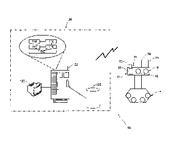
8 With reference to Figure 1, there is shown a system 10 in accordance with an
embodiment of
9 the present invention that relates to mining.
The system 10 comprises a scanning module 12 which, in this case, includes two
hyperspectral
11 cameras 16 arranged to take measurements relating to the chemical
characteristics of an area
12 of interest (in the presently described embodiment, a "bench face" of a
mine bench).
13 The scanning module 12 also includes a geometry scanner 14 for taking
measurements relating
14 to geometirical characteristics of the region of interest. The geometry
scanner 14 may include a
RGB camera 23 and a range scanner 25. For example, and as noted below, one
possible
16 geometry scanner 14 is the Riegl LMS-Z420i laser scanner which is provided
with a range
17 scanner (in the form of a laser) and co-mounted RGB camera. The geometry
scanner 14 in this
18 instance is used for Lidar scanning.
19 Alternative geometry scanners and scanning techniques are possible, such as
radars and
sonars (depending, of course, on the characteristics of the area of interest).
Alternatively,
21 passive sensors/sensing techniques may be used, e.g. a camera for measuring
the light
22 reflected by an object in the region of interest in order to get a spatial
representation of an object
23 spectrum. While a camera only gives a 2D representation, three-dimensional
information may
24 be obtained by taking several pictures from different vantage points and
using triangulation
methods (i.e. stereopsis).
26 To enable absolute positional information to be provided as part of the
geometric information the
27 vehicle 18 is also provided with a receiver (not shown) for receiving GPS
signals.
7
21861098.1
CA 02657161 2009-03-04
1 The scanning module 12 is coupled to a mobile vehicle 18 which may be a self-
propelled
2 vehicle or may be a trailer or similar to be towed behind a prime mover. The
vehicle or prime
3 mover may be directly contolled by a driver, under remote robotic control,
or may be an
4 autonomous (i.e. artificially intelligent) unit. The vehicle 18 carries a
transmitter 19 for
transmitting measurement data from the hyperspectral cameras 16 and geometry
scanner 14 to
6 a processing station 20. In an embodiment the measurement data is
transmitted using standard
7 radio frequency protocol.
8 The processing station 20 is in the form of a remotely located computing
system coupled to a
9 receiver 22. As previously described, the computing system 20 is operable to
process the
measurement data gathered by both the hyperspectral cameras 14 and geometry
scanner 16 so
11 as to produce geological survey data and generate a three dimensional
terrain model providing
12 high spatial and spectral coverage of the bench face. The geological survey
data and terrain
13 map can subsequently be utilised by the system 20 to make ore grade
assessments of material
14 throughout the bench face and, in accordance with those assessments (either
solely or in
combination with further input) to classify the material for extraction and
further treatment
16 according to grade.
17 An initial assessment may be obtained from a first scan of the bench face
taken either before or
18 after drilling but before blasting. The initial assessment may then be
refined to allow for
19 generation of a final classification of ore grades in the bench by
combining the initial
assessment with data taken from one or more subsequent scans of the bench
face, and/or with
21 data obtained by inspection of drill cuttings. The final
determination/assessment and
22 classification of ore grades can then be used to determine treatment of the
mined material.
23 Comparing an initial pre-blasting model (constructed by use of a pre-
blasting scan/assessment)
24 with a post-blasting model (constructed by use of a post-blasting
scan/assessment) can also be
used to assess movement of material in the bench during the blasting.
26 The computing system 20 may also store a model of ore resources in the mine
and use the
27 hyperspectral and/or Lidar data to update the model.
8
21861098.1
CA 02657161 2009-03-04
1 Figure 2 provides a block diagram of the processes 30 involved in using data
from the scanning
2 module 12 to provide a three dimensional geological map/model.
3 In process 32 data from the range scanner 25 is used by the processing
station 20 to generate
4 range data (or a range image) in respect of the bench.
In process 34 data from the RGB camera 23 is used by the processing station 20
to generate a
6 RGB data (or an RGB image) of the bench. Generation of the RGB data may
require actual
7 processing per se, or usable RGB data may be provided directly to the
processing station 20 by
8 the RGB camera 23.
9 In process 36 the processing station 20 generates a geometric representation
of the bench by
registering (fusing) the range data of process 32 with the RGB data of process
34. This
11 registration may be achieved in a number of ways. For example, if the Riegl
LMS-Z420i scanner
12 is used, the scanner is arranged and calibrated such that the RGB camera 23
(providing RGB
13 data) and the laser scanner 14 (providing range data) have aligned co-
ordinate axes which can
14 be used in registering the range data with the RGB picture. Software is
provided with the Riegl
LMS-Z420i scanner that can be used for this registration.
16 In process 38 data from the hyperspectral cameras 16 is used by the
processing station 20 to
17 generate hyperspectral data (or a hyperspectral image) relating to the
bench.
18 In process 40 thematic mapping is used to analyse the hyperspectral data
generated in process
19 38 and classify substances in the bench. As is known in the art, thematic
mapping involves
looking at the absorption bands shown in the hyperspectral image and mapping
regions (or, if
21 desired, individual pixels) of the data to substances by matching
absorption bands of known
22 substances (e.g. iron or haematite) with those substances.
23 In process 42 the processing station 20 generates the three-dimensional
geological map by
24 registering (or fusing) the classification data of process 40 with the
geometric data of process 36
(i.e. the already registered geometric and RGB data). Registration here may,
for example, be
26 achieved by applying standard image processing techniques (such as edge
detection) to the
9
21861098.1
CA 02657161 2009-03-04
1 RGB data and the classification data. Alternatively, and as noted below,
calibration boards may
2 be used to register the classification data with the geometric data.
3 It will be appreciated that the processes described above may be performed
serially or in
4 parallel (except, of course, where one process requires input from a
preceding process). For
example, processes 38 to 40 may run in parallel with processes 32 to 36.
6 To achieve the above functionality, the processing station 20 may employ
standard computer
7 hardware such as a motherboard 110, a central processing unit 112, a random
access memory
8 114, a hard disk 116, and networking hardware 118. In addition to the
hardware, the system 20
9 includes an operating system (such as the Microsoft Windows TM XP Operating
System, which
is made by Microsoft Corporation) that resides on the hard disk and which co-
operates with the
11 hardware to provide an environment in which the software applications can
be executed. In this
12 regard, the hard disk 116 of the server 14 is loaded with a processing
module which operates to
13 generate the geological survey data and terrain model, as previously
described and make
14 associated ore grade assessments.
An instructing module may also be provided for issuing an excavation
instruction dependent, at
16 least in part, on ore grade assessments output from the processing module.
A visual display
17 unit 120 is also provided for graphically displaying the terrain map to a
user. The computing
18 system 20 is coupled to a database 122 for storing the aforementioned
measurement data,
19 geological survey data, terrain map data and model data.
In more detail, a scanning module 12 may utilise commercially available
hyperspectral cameras
21 and laser scanners. For example, for examination of iron ore bodies it has
been found that Neo
22 HySpex VNIR and SWIR cameras having the following characteristics are
suitable.
21861098.1
CA 02657161 2009-03-04
1
Sensor VNIR 1600 SWIR 320m
Spectral range 0.4-1 m 1.3-2.5 m
Spatial pixels 1600x1200 320x256
# bands 160 256
Digitisation 12 bit 14 bit
2
3 The VNIR camera may be used to detect iron ore whereas clay minerals can be
detected by
4 SWIR images. Different cameras may be used either alone or in combination
depending on the
nature of the data desired.
6 An appropriate geometry scanner (if Lidar techniques are to be used) is a 3D
laser scanner
7 such as the Riegl LMS-Z420i scanner which is provided with both a laser and
RGB camera and
8 has the following characteristics.
9
Sensor LMS Z420i
Measurement range 1000 m
Minimum range 2 m
Accuracy 10 mm
Laser wavelength Near infrared
Scanning vertical range 0-80 deg.
Scanning horizontal range 0-360 deg.
Angular resolution 0.002 deg.
11
21861098.1
CA 02657161 2009-03-04
1 The hyperspectral cameras and geometry scanner have inbuilt scanning
movements allowing
2 them to be mounted to the movable vehicle 18 for operation to scan
surrounding landscape.
3 The cameras and scanner may be configured to continuously scan the
surrounding landscape
4 while the vehicle is moving, or may take periodic measurements from selected
locations (either
during movement of the vehicle or while the vehicle is stationary).
6 A raw hyperspectral image consists of a set of digital numbers (DNs) without
physical units.
7 Using the camera parameters, these digital values are converted to at-sensor
radiance [W.nm-
8'.sr'.m"2.]. Radiance is in part dependent on the spectrum intensity of the
input solar energy
9 and as such it is not useful for comparison with libraries or work with
multi-temporal or multi-
sensor data. To normalise the data, the pixel radiance is divided by the
incident light radiance.
11 This process gives reflectance.
12 There are different methods to calculate reflectance. A number of empirical
techniques have
13 been developed which do not make explicit use of atmospheric data and
models. For this
14 reason they are usually referred as normalisation techniques. One
normalisation technique
which can be employed is to use a calibration board having a known spectrum
and from which
16 is possible to calculate the radiance of the incident light to enable the
image to be converted to
17 reflectance. A series of calibration boards may be placed at spatial
locations throughout/along
18 the bench face for this purpose.
19 If used, calibration boards may also be used for registration of
hyperspectral data with geometry
data (as described in process 42 above).
21 The system 10 as described above may be used at an open pit mine as
follows:
22 1. Obtaining information from the mine as excavated, prior to drill and
blast. This
23 can establish a starting point for registration of mineralisation,
comparison and update of
24 a resource model. Coating of dust on rock surfaces may be an issue and so
there may
be a need to identify the differences between dry and wet scans following wash
down
26 using a watercart or rain.
12
21861098.1
CA 02657161 2009-03-04
1 2. Obtaining information post drilling by hyperspectral scanning of faces
and drill
2 cuttings (drill cones). This can highlight the mineralisation and coarse
geometry of
3 material lying within the bench.
4 3. Obtaining information post blasting to assess movement of mineralisation.
Again,
the effect of dust coating can, if necessary, be addressed by washing down of
the area
6 in order to obtain accurate estimates.
7 4. Obtaining information during excavation to provide a continuous
assessment of
8 exactly what is being mined. This will enable reconciliation and dynamic
adjustment of
9 excavation instructions, ie. what of the excavated material is ore and what
is waste. This
also enables a resource model to be updated dynamically using data fusion
techniques.
11 5. Processing of the data to extrapolate the geometry, mineralisation
continuity and
12 grade beneath the bench and laterally to update the resource model.
13 It will be understood by persons skilled in the art that the vehicle and
processing system may
14 communicate using any suitable communication technique and is not limited
to the actual
communication technique described above. For example, communication may be
made over
16 any wireless or wired network including radio networks, infra-red networks,
local area networks
17 and the like.
18 Equally, the aforementioned processing system could be implemented by any
appropriate
19 computer software and hardware and is not limited to the particular
architecture shown in the
drawings and described embodiment. Any particular architecture could be used
including client
21 server arrangements, mainframes, stand-alone or networked computers, and
the like. For
22 example, the system could be entirely incorporated into a single stand-
alone configuration
23 whereby the personal computer includes all of the modules operable to
implement the afore-
24 mentioned embodiments. For example, the processing station could be
provided "on-board" the
vehicle such that all of the modules are integrated into a single unit.
26 While the invention has, for the purposes of illustration, been described
above in relation to a
27 mining application, it will be appreciated alternative applications of the
invention are possible. In
13
21861098.1
CA 02657161 2009-03-04
1 general terms, and referring to figure 3, the invention may be used to
develop a three-
2 dimensional model of a region of interest, the model including both
geometric information and
3 chemical composition information.
4 In step 52 the vehicle 18 with scanning module 12 traverses a region of
interest to take an initial
scan of that region with the hyperspectral cameras 16 (providing chemical
composition
6 information) and the geometric scanner 14 (providing geometric information).
Depending on the
7 terrain, the vehicle 18 may be adapted to traverse the region by flight,
wheeled conveyance, or
8 under/over water conveyance.
9 In step 54 data from the initial scan is provided to the processing station
20. As discussed
above, the data may be sent to the processing station 20 via a wireless
communication protocol.
11 Alternatively, the processing station 20 may be carried by the vehicle 18
and data provided to it
12 by a wired communication protocol.
13 In step 56 the processing station 20 fuses the chemical composition
information and geometric
14 information in order to produce a three dimensional model of the region of
interest, the model
providing information on both the geometry and chemical composition of the
region of interest.
16 In step 58, and if desired/require, the vehicle 18 may again traverse all
or part of the region of
17 interest to take a further scan and obtain further geometric and chemical
composition
18 information.
19 In step 60 the data from the further scan is provided to the processing
station 20, and in step 62
the data processing station 20 uses the data from the further scan to either
update the model of
21 step 56 and/or create a new model. Updating the model generated in step 56
may be
22 appropriate where further accuracy is required. Creation of a further model
of the region may be
23 of use when a comparison between the region at the time of the initial scan
and the region at
24 the time of the further scan is desired.
Steps 58 to 62 may be repeated as is required or desired or, if only one scan
is required,
26 omitted entirely.
14
21861098.1
CA 02657161 2009-03-04
1 At step 64 the models generated in step 58 and/or step 62 are used. As will
be appreciated, the
2 actual use of the model(s) will depend on the application.
3 For example, in the mining embodiment described above the models may be used
to determine
4 the most aippropriate drilling locations, to classify and process ore,
and/or to determine
movement within the mine after blasting.
6 The term "comprises" (and its grammatical variants) as used herein is
equivalent to the term
7 "includes" and should not be taken as excluding the existence of additional
features, steps or
8 integers.
9 It will be understood that the invention disclosed and defined in this
specification extends to all
alternative combinations of two or more of the individual features mentioned
or evident from the
11 text or drawings. All of these different combinations constitute various
alternative aspects of the
12 invention.
21861098.1