Language selection

Search

Patent 2657500 Summary

Third-party information liability

Some of the information on this Web page has been provided by external sources. The Government of Canada is not responsible for the accuracy, reliability or currency of the information supplied by external sources. Users wishing to rely upon this information should consult directly with the source of the information. Content provided by external sources is not subject to official languages, privacy and accessibility requirements.

Claims and Abstract availability

Any discrepancies in the text and image of the Claims and Abstract are due to differing posting times. Text of the Claims and Abstract are posted:

  • At the time the application is open to public inspection;
  • At the time of issue of the patent (grant).
(12) Patent Application: (11) CA 2657500
(54) English Title: CURRENT-INSULATING SYSTEM FOR FLUID SYSTEMS
(54) French Title: SYSTEME D'ISOLATION DE COURANT POUR SYSTEMES DE FLUIDES
Status: Deemed Abandoned and Beyond the Period of Reinstatement - Pending Response to Notice of Disregarded Communication
Bibliographic Data
(51) International Patent Classification (IPC):
  • F16L 25/02 (2006.01)
  • B64D 37/32 (2006.01)
  • B64D 45/02 (2006.01)
(72) Inventors :
  • FERNANDEZ VIEIRA, JESUS (Spain)
(73) Owners :
  • AIRBUS OPERATIONS S.L.
(71) Applicants :
  • AIRBUS OPERATIONS S.L. (Spain)
(74) Agent: SMART & BIGGAR LP
(74) Associate agent:
(45) Issued:
(86) PCT Filing Date: 2006-06-22
(87) Open to Public Inspection: 2008-01-03
Examination requested: 2011-06-15
Availability of licence: N/A
Dedicated to the Public: N/A
(25) Language of filing: English

Patent Cooperation Treaty (PCT): Yes
(86) PCT Filing Number: PCT/ES2006/070088
(87) International Publication Number: ES2006070088
(85) National Entry: 2008-12-18

(30) Application Priority Data: None

Abstracts

English Abstract

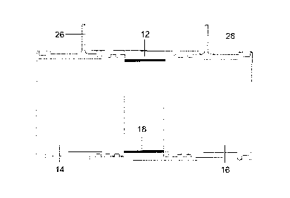
An electrical insulating system for a line element that forms part of a fluid system subjected to risks of possible external electrical discharges, such as the fuel system of an aircraft. Use is made of an insulating insert (12) between two parts (14, 16) of said line element, consisting in providing said parts (14, 16) with grooved edges and in forming the insulating insert (12) between them by means, preferably, of an injection technique, such that said insulating insert (12) provides an interior conduit for the passage of fluid between said parts (14, 16) and covers said grooved edges, guaranteeing the leak tight joining of the insulating insert (12) and said parts (14, 16).


French Abstract

L' invention concerne un système d'isolation électrique pour un élément linéaire faisant partie d'un système de fluides soumis à des risques d'éventuelles décharges électriques externes, de type système de combustible d'un aéronef. Ce système comprend un insert isolant (12) disposé entre deux parties (14, 16) dudit élément linéaire et consiste à doter lesdites parties (14, 16) de bords rainurés et à conformer l'insert isolant (12) entre les deux parties au moyen, de préférence, d'une technique d'injection, de façon que ledit insert isolant (12) constitue un conduit intérieur permettant d'assurer le passage de fluide entre lesdites parties (14, 16) et recouvre lesdits bords rainurés tout en garantissant un raccord étanche entre l'insert isolant (12) et lesdites parties (14, 16).

Claims

Note: Claims are shown in the official language in which they were submitted.


6
CLAIMS
1. An electrical insulation system for a linear element in
a fluid system subjected to risks of possible external
electrical discharges, the electrical insulation system
comprising an insulating insert (12) between two parts (14, 16)
of said linear element, characterized in that:
a) said parts (14, 16) have grooved edges comprising
diametric grooves (20) and longitudinal grooves (22);
b) the insulating insert (12) is a piece of insulating
material formed between said parts (14, 16) such that it
provides an internal duct for the passage of fluid between said
parts (14, 16) and covers said grooved edges, assuring the leak-
tight joint of the insulating insert (12) with said parts (14,
16) without needing specific means for it such as gaskets or
rubber seals with the subsequent reduction in maintenance costs.
2. An electrical insulation system for a linear element in
a fluid system according to claim 1, characterized in that the
formation of the insulating insert (12) is carried out by means
of an injection technique using a suitable mold.
3. An electrical insulation system for a linear element in
a fluid system according to claims 1-2, characterized in that
the material of the insulating insert (12) is chosen from PEEK,
polyamide and nylon.
4. An electrical insulation system for a linear element in
a fluid system according to claims 1-3, characterized in that
the area (18) of the insulating insert (12) located between the
edges of said parts (14, 16) has a minimum length of 25 mm.
5. An electrical insulation system for a linear element in
a fluid system according to claims 1-4, characterized in that
the linear element is a metal pipe.
6. An electrical insulation system for a linear element in
a fluid system according to any of the previous claims,
characterized in that the fluid system belongs to an aircraft.
7. An electrical insulation system for a linear element in
a fluid system according to claim 6, characterized in that the
fluid system is a fuel system.
8. An electrical insulation system for a linear element in
a fluid system according to any of the previous claims,

7
characterized in that said parts (14, 16) include bonding point
elements (26, 28).

Description

Note: Descriptions are shown in the official language in which they were submitted.


CA 02657500 2008-12-18
1
CURRENT-INSULATING SYSTEM FOR FLUID SYSTEMS
FIELD OF THE INVENTION
The invention relates to an insulation system for fluid
systems subjected to risks of possible electrical discharges
using insulating inserts between parts of the linear elements of
the fluid system, and more specifically to an insulation system
for protecting aircraft fuel systems against electrical
discharges caused by lightening striking fuel deposits made of
materials with low electrical conductivity.
BACKGROUND OF THE INVENTION
Composite materials provide high electrical resistance in
comparison with metallic materials. The latter have
traditionally been used in the field of aeronautics for the
manufacture of structures intended for fuel storage given their
mechanical characteristics in relation to the weight of these
materials.
The high electrical resistance inherent to composite
materials causes a highly relevant induction effect in internal
fuel tank systems. Said effect induces internal electrical
currents that may give way to catastrophic failures or phenomena
for the overall structural integrity.
The phenomena related to moderate or severe electrical
discharges occurring in the case of lightening striking which
must be avoided in a structure made of a material with low
electrical conductivity so as to assure its structural
integrity/malfunction of any of the critical electrical
equipment/electric arcs inside the tank:
Hot spots: the high density of current in certain specific
locations of the structure such as joints or intersection
elements may generate high temperature spots. If this
temperature exceeds 200 C (point of auto-ignition of the fuel
considered by FAA/JAA authorities) the fuel may reach its
ignition point.
Electric arcs (sparking): the flow of current through
materials with different resistances and in geometrically spaced
locations may cause discharges in the form of an electric arc
(potential difference) and causing the ignition of the

CA 02657500 2008-12-18
2
fuel/inflammable liquid contained in the structure.
Electrical equipment malfunction: the electrical discharges
caused by lightening striking give way to high levels of current
circulating through the outer structure and may therefore
introduce electric current through the internal systems either
by shunting or induction. These effects are capable of causing
critical equipment malfunction, generating a catastrophic
failure.
Patent application PCT/ES05/070133 of Airbus describes a
method for protecting the assembly of metallic devices assembled
inside a fuel tank, completely or partially manufactured with
composite materials, for protection against electrical
discharges, in which insulating inserts are required in the
installation lines for the fuel, ventilation, etc., such that
they are subdivided into parts insulated from one another.
This invention relates to an insulating insert of the type
that can be used both in locations with little free space and in
areas of insulating floating elements with greater length.
SUMMARY OF THE INVENTION
This invention proposes an electrical insulation system for
a linear element that is part of a fluid system subjected to
risks of possible external electrical discharges using an
insulating insert between two parts of said linear element,
according to which said parts are provided with grooved edges
and the insulating insert is a piece of insulating material that
is formed between said parts such that it provides an internal
duct for the passage of fluid between them and covers said
grooved edges, assuring the leak-tight joint of the insulating
insert with the two parts of the linear element.
The insulating insert is preferably formed by means of an
injection technique using a suitable mold.
The linear elements to which the insulation system is
applied is preferably a metal pipe for the passage of fuel and
the grooved edges of the parts between which the insulating
insert is located include diametric grooves so as to facilitate
the coupling of the insulating insert and longitudinal grooves
to prevent the rotation thereof.
The insulation system object of this invention is

CA 02657500 2008-12-18
3
applicable to fuel and ventilation pipes forming part of fuel
systems installed in aircraft when it is necessary to stop the
current or else insulate sections of the installation where the
passage thereof is foreseen.
An advantage of the system object of the present invention
is that the insulating insert is joined to the two parts of the
linear element without needing mechanical jointing elements such
as bolts, rivets, washers or nuts.
Another advantage of the system object of the present
invention is the leak-tight nature of the joint between the
insulating insert and the two parts of the linear element,
without needing specific means for it such as gaskets or rubber
seals with the subsequent reduction in maintenance costs.
Another advantage of the system object of this invention is
the reduction in manufacturing and assembly costs as the
machined pieces made of difficult to elaborate insulating
material are eliminated.
Another advantage of the object of this invention is the
reduction in weight resulting from not using specific jointing
and leak-tight elements.
Other features and advantages of this invention shall be
understood from the detailed and illustrated description of the
object with the attached figures.
DETAILED DESCRIPTION OF THE DRAWINGS
Figure 1 shows a sectional view of two parts of a pipe with
an insulating insert according to the system object of this
invention.
Figure 2 shows a perspective view of a pipe with an
insulating insert according to the system object of this
invention.
Figure 3 shows a perspective view of the two parts of the
pipe before forming the insulating insert between them.
DETAILED DESCRIPTION OF THE INVENTION
In Figures 1, 2 and 3, which show a preferred embodiment of
the invention, it can be seen that the insulating insert 12 is a
piece joined in a leak-tight manner to parts 14, 16 of a metal
pipe. Such joint occurs when the insulating insert 12 is formed
between said parts 14, 16 by means of any suitable technique.

CA 02657500 2008-12-18
4
Therefore specific jointing and/or leak-tight elements are not
used.
A suitable technique is injection using a suitable mold
(not shown) resulting in a cylindrical-shaped insulating insert
12. The injection can be carried out either externally or
internally, preventing internal stepping according to needs.
Nylon, polyamide and PEEK are some of the preferred insulating
materials that can be used.
The edges of parts 14, 16 of the metal pipe are grooved so
as to facilitate the leak-tight joint of the insulating insert
12 formed in situ. For the purpose of this invention, the
expression "grooved edges" must be understood in the broadest
sense, including any type of striated structure allowing the
expressed purpose.
In the preferred embodiment shown in the Figures, parts 14,
16 of the metal pipe have edges with diametric grooves 20 and
longitudinal grooves 22 so as to facilitate the fixing of the
insulating insert 12.
The insulating insert 12 must be sized such that it
prevents the passage of electric current when it circulates
through the fuel or ventilation pipes in which it is inserted.
From the technical point of view, said insert is subjected
to insulation tests during which it is subjected to a potential
difference between the ends of between 500 VDC and 1000 VDC,
providing electrical insulation of the order of 100 Mega ohms as
a minimum requirement.
In this sense it is estimated that the minimum length of
the area 18 of the insulating insert 12 located between parts 14,
16 of the metal pipe must be at least 25 mm so as to comply with
the requirements for insulation against lightening and static
current.
As previously mentioned, the insulating insert 12 is
applicable to fuel installations in which the intention is to
insulate the current in sections or to apply a single bonding
point philosophy.
With the required material and dimensions it is also
applicable to aircraft systems other than fuel systems, such as
for example the hydraulic or pneumatic circuit as it has not

CA 02657500 2008-12-18
mechanical jointing elements (which would have to be provided
with systems for withstanding the high pressures) and expendable
jointing elements (gaskets) resistant to different fluids
(hydraulic fluids for example).
5 In the case of fuel systems, parts 14, 16 of the metal pipe
must include elements 26, 28 for installing a bonding point
since a double bonding point is required in these systems.
These elements 26, 28 will be machined at said parts 14, 16
with the minimum thickness necessary and provided with two bores
so as to be able to give them electrical continuity with the
rest of the corresponding fluid system line.
Modifications can be introduced in the preferred embodiment
just described that are comprised within the scope defined by
the following claims.

Representative Drawing
A single figure which represents the drawing illustrating the invention.
Administrative Status

2024-08-01:As part of the Next Generation Patents (NGP) transition, the Canadian Patents Database (CPD) now contains a more detailed Event History, which replicates the Event Log of our new back-office solution.

Please note that "Inactive:" events refers to events no longer in use in our new back-office solution.

For a clearer understanding of the status of the application/patent presented on this page, the site Disclaimer , as well as the definitions for Patent , Event History , Maintenance Fee  and Payment History  should be consulted.

Event History

Description Date
Application Not Reinstated by Deadline 2013-06-25
Time Limit for Reversal Expired 2013-06-25
Deemed Abandoned - Failure to Respond to Maintenance Fee Notice 2012-06-22
Letter Sent 2011-10-19
Letter Sent 2011-07-05
Request for Examination Received 2011-06-15
All Requirements for Examination Determined Compliant 2011-06-15
Request for Examination Requirements Determined Compliant 2011-06-15
Inactive: Cover page published 2009-05-08
Letter Sent 2009-04-21
Inactive: Notice - National entry - No RFE 2009-04-14
Inactive: First IPC assigned 2009-04-03
Application Received - PCT 2009-04-02
Inactive: Single transfer 2009-03-04
National Entry Requirements Determined Compliant 2008-12-18
Application Published (Open to Public Inspection) 2008-01-03

Abandonment History

Abandonment Date Reason Reinstatement Date
2012-06-22

Maintenance Fee

The last payment was received on 2011-05-20

Note : If the full payment has not been received on or before the date indicated, a further fee may be required which may be one of the following

  • the reinstatement fee;
  • the late payment fee; or
  • additional fee to reverse deemed expiry.

Patent fees are adjusted on the 1st of January every year. The amounts above are the current amounts if received by December 31 of the current year.
Please refer to the CIPO Patent Fees web page to see all current fee amounts.

Owners on Record

Note: Records showing the ownership history in alphabetical order.

Current Owners on Record
AIRBUS OPERATIONS S.L.
Past Owners on Record
JESUS FERNANDEZ VIEIRA
Past Owners that do not appear in the "Owners on Record" listing will appear in other documentation within the application.
Documents

To view selected files, please enter reCAPTCHA code :


To view images, click a link in the Document Description column. To download the documents, select one or more checkboxes in the first column and then click the "Download Selected in PDF format (Zip Archive)" or the "Download Selected as Single PDF" button.

List of published and non-published patent-specific documents on the CPD .

If you have any difficulty accessing content, you can call the Client Service Centre at 1-866-997-1936 or send them an e-mail at CIPO Client Service Centre.


Document
Description 
Date
(yyyy-mm-dd) 
Number of pages   Size of Image (KB) 
Description 2008-12-17 5 199
Representative drawing 2008-12-17 1 8
Abstract 2008-12-17 1 16
Claims 2008-12-17 2 49
Drawings 2008-12-17 2 97
Notice of National Entry 2009-04-13 1 194
Courtesy - Certificate of registration (related document(s)) 2009-04-20 1 103
Reminder - Request for Examination 2011-02-22 1 117
Acknowledgement of Request for Examination 2011-07-04 1 178
Courtesy - Abandonment Letter (Maintenance Fee) 2012-08-16 1 172
PCT 2008-12-17 13 352