Language selection

Search

Patent 2657557 Summary

Third-party information liability

Some of the information on this Web page has been provided by external sources. The Government of Canada is not responsible for the accuracy, reliability or currency of the information supplied by external sources. Users wishing to rely upon this information should consult directly with the source of the information. Content provided by external sources is not subject to official languages, privacy and accessibility requirements.

Claims and Abstract availability

Any discrepancies in the text and image of the Claims and Abstract are due to differing posting times. Text of the Claims and Abstract are posted:

  • At the time the application is open to public inspection;
  • At the time of issue of the patent (grant).
(12) Patent Application: (11) CA 2657557
(54) English Title: PIPE STRING DEVICE FOR CONVEYING A FLUID FROM A WELL HEAD TO A VESSEL
(54) French Title: DISPOSITIF DE TRONCON DE CANALISATION PERMETTANT DE TRANSPORTER UN FLUIDE DEPUIS UNE TETE DE PUITS JUSQU'A UNE CUVE
Status: Deemed Abandoned and Beyond the Period of Reinstatement - Pending Response to Notice of Disregarded Communication
Bibliographic Data
(51) International Patent Classification (IPC):
  • F17D 1/12 (2006.01)
  • E21B 21/12 (2006.01)
  • E21B 43/12 (2006.01)
(72) Inventors :
  • STAVE, ROGER (Norway)
(73) Owners :
  • AGR SUBSEA AS
(71) Applicants :
  • AGR SUBSEA AS (Norway)
(74) Agent: SMART & BIGGAR LP
(74) Associate agent:
(45) Issued:
(86) PCT Filing Date: 2007-07-13
(87) Open to Public Inspection: 2008-01-17
Availability of licence: N/A
Dedicated to the Public: N/A
(25) Language of filing: English

Patent Cooperation Treaty (PCT): Yes
(86) PCT Filing Number: PCT/NO2007/000269
(87) International Publication Number: WO 2008007973
(85) National Entry: 2009-01-12

(30) Application Priority Data:
Application No. Country/Territory Date
20063269 (Norway) 2006-07-14

Abstracts

English Abstract

A method and pipe string device (1) for conveying a fluid from a well head (2) to a vessel (8), the fluid in the pipe string (1) needing, for well-technical reasons, to be given a flow boost, and the pipe string (1) being provided with at least one injection point for a driving fluid, the injection point may be constituted by an ejector (20).


French Abstract

Le procédé et dispositif de tronçon de canalisation (1) de la présente invention permet de transporter un fluide depuis une tête de puits (2) jusqu'à une cuve (8), le fluide dans le tronçon de canalisation (1) devant, pour des raisons techniques liées aux puits, se voir attribuer une impulsion d'écoulement, et le tronçon de canalisation (1) étant équipé d'au moins un point d'injection pour un fluide moteur, lequel point d'injection peut être constitué par un éjecteur (20).

Claims

Note: Claims are shown in the official language in which they were submitted.

C l a i m s
1. A pipe string device (1) for conveying a fluid from a
well head (2) to a vessel (8) during a drilling phase
of a well, the fluid located in the pipe string (1)
needing, for well-technical reasons, to be given a
flow boost, characterized in that the
pipe string (1) that is anchored on the sea floor (4),
is provided with at least one injection point for a
driving fluid.
2. The device in accordance with claim 1, charac-
terized in that the injection point is con-
stituted by a fluid-operated ejector (20).
3. The device in accordance with claim 1, charac-
terized in that a mechanically working pump
(24) is connected to the pipe string (1).
4. The device in accordance with claim 1 , charac-
terized in that the pipe string (1) leads
into a separator tank (6) on the vessel (8).
5. The device in accordance with claim 1, charac-
terized in that the pipe string (1) is anc-
hored on the sea floor (4) by means of an anchor (14)
and provided with a buoyancy body (18) near the sea
surface (16 ) .
6. The device in accordance with claim 1, charac-
terized in that the pipe string (1) is sus-
pended from the vessel (8) and connected to the well
head (2) by means of a flexible connection.
7. A method of providing flow assistance to a fluid lo-
cated in a pipe string (1) during the drilling phase

2
of a well, the fluid being conveyed by means of the
pipe string (1) from a well head (2) to a vessel (8),
characterized in that the pipe string
(1) is supplied with a driving fluid that has a lower
density than the conveyed fluid at least at one injec-
tion point located on the pipe string (1).
8. The method in accordance with claim 7, charac-
terized in that at the injection point there
is supplied a driving fluid which has a lower specific
gravity than the fluid located in the pipe string.

Description

Note: Descriptions are shown in the official language in which they were submitted.


CA 02657557 2009-01-12
WO 2008/007973 PCT/N02007/000269
Pipe string device for conveying a fluid from a well head to
a vessel.
This invention relates to a pipe string. More particularly,
it relates to a pipe string for conveying a fluid from a well
head to a vessel, in which, for well-technical reasons, the
fluid located in the pipe string needs to be given a flow
boost, and in which the pipe string is provided along its
length with at least one injection point for a driving fluid.
The injection point may be formed by a fluid-operated
ejector. The invention also includes a method of using the
io device.
In the drilling for and recovery of petroleum it is
necessary, for drilling- and well-technical reasons, to use a
well fluid which is adapted for the conditions in the well
with respect to density and viscosity, among other things. It
is is common, for example, to use drilling fluid having a
density of approximately 1.6 kg/l.
During the first phase of the drilling it has previously been
common to use "disposable drilling fluid" and deposit the
effluent cuttings on the sea floor, which is unfavourable to
20 the environment and which also means increased costs.
US patent 6745851 deals with work of this kind and discloses
a pump-operated solution which can recover and recirculate
the drilling fluid.
RECTIFIED SHEET (RULE 91)

CA 02657557 2009-01-12
WO 2008/007973 PCT/N02007/000269
2
In drilling at great depths offshore, the head from the
drilling vessel down to the well formation may become so
great that drilling fluid penetrates into the formation. Such
a flow of drilling fluid into the formation is unfortunate
both because relatively expensive drilling fluid is lost, but
also because an inflow of this kind may reduce the future
productivity of a well.
A method which has gained some ground in offshore wells
involves the drilling fluid being pumped, as it is returning
zo from the borehole, out at the well head on the sea floor,
then flowing back to the vessel via a separate pipe.
In this way the static pressure in the borehole can be
controlled, for example by controlling the liquid head in the
riser, if such is installed, between the well head and
vessel.
NO patent 319213 (W02005052307) discloses a method directed
towards controlling the liquid pressure in the well by
filling the upper portion of the riser with a fluid having a
different density relative to the density of the drilling
fluid.
At relatively great sea depths, at which the return pipe
necessarily is long, the necessary pump pressure at the sea
floor is relatively high because of the density and viscosity
of the drilling fluid. It has turned out to be difficult to
achieve the necessary flow rate without having to use pipes
of a relatively large diameter, which entails increased pipe
weight and thereby considerably higher investment costs.
The invention has as its object to remedy or to reduce at
least one of the drawbacks of the prior art.
The object is achieved through features specified in the

CA 02657557 2009-01-12
WO 2008/007973 PCT/N02007/000269
3
description below and in the claims that follow.
A pipe string in accordance with the invention for conveying
a fluid from a well head to a vessel, in which the fluid
located in the pipe string needs, for well-technical reasons,
to be given a flow boost, is characterized by the pipe string
being provided along its length with at least one injection
point for a driving fluid.
The injection point is most advantageously constituted by a
fluid-operated ejector.
One such injection point or more can be disposed at suitable
intervals along the pipe string from the sea floor and up to
the vessel. The pipe string forms a separate flow path
relative to a possible riser.
When the injection point is constituted by an ejector, a
possible ejector located above will relieve the ejector
located below, so that this ejector starts a flow feeding the
ejector located above with fluid.
Alternatively, a pump may be arranged, pumping the fluid
through the pipe string, one or more ejectors at the upper
portion of the pipe string forming auxiliary apparatuses for
a sufficient flow rate through the pipe string to be
achieved.
Typically, the driving fluid has a lower density than the
fluid located in the pipe string. Thus, on injection of a
second fluid the overall liquid pressure within the fluid
string at the sea floor will be reduced.
If the second fluid comprises a gas, the gas may expand as it
rises in the pipe string, thereby further reducing the
overall liquid pressure within the pipe string at the sea

CA 02657557 2009-01-12
WO 2008/007973 PCT/N02007/000269
4
floor.
The pipe string may be anchored on the sea floor and be
provided with buoyancy bodies at its upper portion, or it may
be suspended from the vessel which then carries the weight of
the pipe string.
The device and method according to the invention may provide
a satisfactory flow rate in the pipe string, even with the
use of a pipe string of a relatively small diameter.
In what follows is described an example of a preferred
embodiment and method which are visualized in the
accompanying drawings, in which:
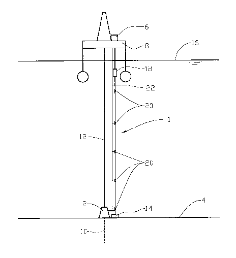
Figure 1 shows schematically a vessel which is provided with
a.pipe string in accordance with the invention; and
Figure 2 shows the invention in an alternative embodiment.
is In the drawings the reference numeral 1 indicates a pipe
string which is connected at its lower end portion to a well
head 2 on the sea floor 4, and which is connected at its
upper end portion to a separator 6. The separator 6 is
located on a vessel 8.
The vessel 8 is typically carrying out work in a well 10 in
the ground and is connected to the well 10 by means of a pipe
connection 12 extending through the well head 2. Dependent on
the operations involved, the pipe connection 12 may comprise,
in a manner known per se, one or more of drill pipe, marine
riser, work riser or other well intervention tools.
The pipe string 1 is anchored on the sea floor 4 by means of
an anchor 14. At its upper portion, near the sea surface 16,
is arranged a buoyancy body 18 which is arranged to take the
weight of the pipe string 1.

CA 02657557 2009-01-12
WO 2008/007973 PCT/N02007/000269
The pipe string 1 is provided with fluid-operated ejectors 20
suitably spaced apart, which are supplied with driving fluid
from the vessel 8 via at least one driving-fluid pipe 22.
When a fluid is to be brought to flow through the pipe string
5 1 from the well head 2, the pressure fluid supply via the
driving-fluid pipe 22 from the vessel 8 to the ejectors 20 is
opened. The flow starts by each ejector 20 supplying the
necessary pressure to the fluid until the fluid flows to the
next ejector along the pipe string 1.
At the vessel 8 the fluid enters the separator 6, in which
possible driving gases are separated from the rest of the
fluid before the remaining fluid flows on for treatment in,
for example, screening machines, not shown.
The return pressure at the well head 2 can be controlled by
adjusting the driving-fluid pressure into the ejectors 20.
In an alternative embodiment, see figure 2, a mechanically
working pump 24 is arranged at the lower portion of the pipe
string 1. The ejectors 20, which are arranged at the upper
portion of the pipe 1, are used here to increase the flow
rate through the pipe string 1 beyond that effected by the
pump 24 on its own.

Representative Drawing
A single figure which represents the drawing illustrating the invention.
Administrative Status

2024-08-01:As part of the Next Generation Patents (NGP) transition, the Canadian Patents Database (CPD) now contains a more detailed Event History, which replicates the Event Log of our new back-office solution.

Please note that "Inactive:" events refers to events no longer in use in our new back-office solution.

For a clearer understanding of the status of the application/patent presented on this page, the site Disclaimer , as well as the definitions for Patent , Event History , Maintenance Fee  and Payment History  should be consulted.

Event History

Description Date
Time Limit for Reversal Expired 2013-07-15
Application Not Reinstated by Deadline 2013-07-15
Inactive: Abandon-RFE+Late fee unpaid-Correspondence sent 2012-07-13
Deemed Abandoned - Failure to Respond to Maintenance Fee Notice 2012-07-13
Letter Sent 2009-10-02
Inactive: Office letter 2009-10-02
Inactive: Delete abandonment 2009-08-18
Inactive: Correspondence - Transfer 2009-08-04
Deemed Abandoned - Failure to Respond to Notice Requiring a Translation 2009-07-20
Inactive: Office letter 2009-06-03
Inactive: Cover page published 2009-05-26
Inactive: Notice - National entry - No RFE 2009-04-21
Inactive: Incomplete PCT application letter 2009-04-20
Inactive: First IPC assigned 2009-04-03
Application Received - PCT 2009-04-02
Inactive: Declaration of entitlement - PCT 2009-03-31
Inactive: Single transfer 2009-03-31
National Entry Requirements Determined Compliant 2009-01-12
Application Published (Open to Public Inspection) 2008-01-17

Abandonment History

Abandonment Date Reason Reinstatement Date
2012-07-13
2009-07-20

Maintenance Fee

The last payment was received on 2011-06-27

Note : If the full payment has not been received on or before the date indicated, a further fee may be required which may be one of the following

  • the reinstatement fee;
  • the late payment fee; or
  • additional fee to reverse deemed expiry.

Please refer to the CIPO Patent Fees web page to see all current fee amounts.

Fee History

Fee Type Anniversary Year Due Date Paid Date
Basic national fee - standard 2009-01-12
MF (application, 2nd anniv.) - standard 02 2009-07-13 2009-01-12
Registration of a document 2009-03-31
MF (application, 3rd anniv.) - standard 03 2010-07-13 2010-06-21
MF (application, 4th anniv.) - standard 04 2011-07-13 2011-06-27
Owners on Record

Note: Records showing the ownership history in alphabetical order.

Current Owners on Record
AGR SUBSEA AS
Past Owners on Record
ROGER STAVE
Past Owners that do not appear in the "Owners on Record" listing will appear in other documentation within the application.
Documents

To view selected files, please enter reCAPTCHA code :


To view images, click a link in the Document Description column. To download the documents, select one or more checkboxes in the first column and then click the "Download Selected in PDF format (Zip Archive)" or the "Download Selected as Single PDF" button.

List of published and non-published patent-specific documents on the CPD .

If you have any difficulty accessing content, you can call the Client Service Centre at 1-866-997-1936 or send them an e-mail at CIPO Client Service Centre.


Document
Description 
Date
(yyyy-mm-dd) 
Number of pages   Size of Image (KB) 
Description 2009-01-12 5 194
Claims 2009-01-12 2 56
Representative drawing 2009-01-12 1 6
Drawings 2009-01-12 2 15
Abstract 2009-01-12 2 59
Cover Page 2009-05-26 1 32
Notice of National Entry 2009-04-21 1 193
Courtesy - Certificate of registration (related document(s)) 2009-10-02 1 102
Reminder - Request for Examination 2012-03-14 1 116
Courtesy - Abandonment Letter (Maintenance Fee) 2012-09-07 1 172
Courtesy - Abandonment Letter (Request for Examination) 2012-10-22 1 165
PCT 2009-01-12 13 425
Correspondence 2009-03-31 2 57
Correspondence 2009-06-03 1 24
Correspondence 2009-10-02 1 15