Note: Descriptions are shown in the official language in which they were submitted.
CA 02657704 2009-03-09
CHUCK-INTEGRATED FORCE-MEASURING SYSTEM
[0001] The present invention relates to a chuck-integrated force-measuring
system
according to the definition of the species set forth in claim 1.
[0002J When working with machine tools, such as NC machines, the execution of
a
machining process, for example the cutting removal of material by turning,
drilling,
milling, broaching, etc., is reflected in the time sequence of specific
physical quantities,
such as the cutting force and/or feed force. By recording and evaluating these
quantities,
the process can then be monitored with regard to the quality of the result
(intelligent
analysis of measurement signals). On this basis, it is likewise possible to
control the
process by considering specific, variable process parameters, such as speed,
feed force,
respectively feed rate, etc., in accordance with specific criteria, for
example machining
quality, machining time, etc., as well as in accordance with a combination of
such criteria.
[0003] In this case, the force that is exerted at the machining point (or the
cutting edge)
of the tool on the workpiece is considered to be a particularly important,
information-bearing physical quantity. It is important to know this cutting
force as
precisely as possible in terms of magnitude and direction, also in the context
of those
machining methods which employ rotating spindles (for example, drilling,
milling, etc.).
Of primary importance in this context is the magnitude of the force - also of
interest is the
resulting direction in the fixed coordinate system.
[0004J A fundamental difficulty arises with regard to recording this force
using
measuring technology. The force is generated at the point of cutting
engagement with an
instantaneous magnitude and direction that are dependent on the cutting
geometry and the
control thereof relative to the workpiece surface and the contour thereof.
[0005] A complete acquisition [recording or sensing] of the resulting force
requires
determining the same in three directions in the fixed coordinate system. This
can be
accomplished theoretically due to the physical law of "actio = reactio," using
the
appropriate measuring sensors either on the workpiece or the tool. In
practice, however,
I
CA 02657704 2009-03-09
there are substantial differences in the measuring results.
[0006] From a technical standpoint, it is easily feasible to provide a
mounting
attachment [to accommodate the measuring sensors] on the workpiece. However,
it is
not economically practical in production practice since the workpiece must be
clamped on
a special measuring table having installed force sensors. Moreover,
particularly in the
context of dynamic forces, on the one hand, the mass of the workpiece
functions as a
low-pass filter which attenuates the higher-frequency signal content and, on
the other
hand, the necessarily finite mass of the measuring table falsifies the signal.
Depending on
the size of the masses involved, these effects limit the validity of the
measurement to a
specific frequency band or even preclude a direct analysis without having to
first perform a
complex model analysis of the entire system.
[0007] If the force measurement is carried out at the tool in order to avoid
the above
problems, the following difficulties arise:
[0008] Direct measurements using force sensors at the cutting-tool tip, for
example,
necessitate appropriate structural design measures for the machine tool. Thus,
an
appropriate installation space for the measuring technology is to be provided,
which is not
sufficiently available when working with conventional machining equipment.
Therefore, at
the present time, these types of measurements are performed, at most, in
highly specialized
laboratory systems, which can only be used under very restrictive conditions
and,
therefore, have only little practical significance.
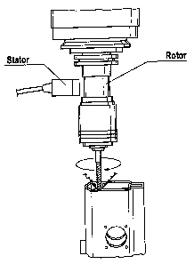
[0009] Thus, from the related art in accordance with the enclosed FIG. 1, what
is
generally referred to as a tool-torque sensing system for drilling machines is
known, which
is composed of a rotor that is attachable to the spindle of a tool holder, and
of a stator
which is mounted in a contactiess configuration around the rotor. The rotor
measures the
torque that is applied to the rotating drilling tool and transmits the
measured values in a
contactless process to the stator. Moreover, it is optionally possible to also
pick off the
feed force at the tool holder spindle.
[0010] As is discernible from FIG. 1, the rotor is located at the output
spindle of the
machine tool above the tool chuck. Thus, this related art also requires that
an appropriate
2
CA 02657704 2009-03-09
space be provided for attaching the rotor.
[0011] In the light of this related art, an object of the present invention is
to provide a
force-measuring system, in particular for machine tools having a rotating
spindle, which
will offer an enhanced functionality, for instance in terms of a more
comprehensive
usability and more precise measuring results.
[0012] This objective is achieved by a chuck-integrated force-measuring system
having
the features set forth in claim 1. Accordingly, the central idea of the
present invention is to
place at least one measuring sensor, in the form of a strain sensor
[extensometer], on a
tool holder of a machine tool. For this purpose, a measuring hub assembly is
advantageously provided, which is insertable as an adapter piece or
intermediate piece into
the chuck of the machine tool and is designed with its own chuck for receiving
the tool, the
at least one measuring sensor being integrated in the adapter piece.
[0013] Thus, the essential principle underlying the present invention is that
the force
sought is determined from the strains occurring in the tool holder. Strains
resulting from
bending and torsional moments arising from the force at the cutting-tool tip
occur, namely,
at the surface of the holder. However, these strains are not measured by the
strain-
measuring sensor directly at the cutting-tool holder, i.e., the chuck or the
output spindle of
the machine tool; rather, the strain-measuring sensors are placed as an
external component
on a measuring hub assembly. The tool is inserted with a defined angular
correlation into
this hub assembly, while the measuring hub assembly, in turn, is accommodated
by the
clamping chuck of the machine tool spindle. The following advantages may be
attained by
employing this measure:
[0014] - The instantaneous force at the cutting-tool tip may be determined in
terms of
magnitude and direction by the strain sensing.
[0015] - The measuring hub assembly may be used for a plurality of different
tools or
machine tools. A cost and time savings is hereby derived.
[0016] - The machine dynamics at the clamping point of the tool are not
substantially
changed. The measuring accuracy is thereby enhanced.
[0017] - The measuring hub assembly does not require any installation space or
any
disturbing stator parts within the range of action of the machine spindles
above the tool
chuck.
3
CA 02657704 2009-03-09
[0018] Other advantageous embodiments of the present invention constitute the
subject
matter of the dependent claims.
[0019] The present invention is clarified in greater detail in the following
on the basis
of a preferred exemplary embodiment and with reference to the accompanying
drawing.
[0020] FIG. 1 shows the basic design of a measuring system for measuring
torques at
the output spindle of a drilling machine in accordance with the related art;
and
[0021] FIG. 2 shows the lateral view of a chuck-integrated force-measuring
system in
accordance with the preferred exemplary embodiment of the present invention.
[0022] In accordance with FIG. 2, the chuck-integrated force-measuring system
of the
present invention is composed of a measuring hub assembly 1 which is equipped
with a
number of strain-measuring sensors (not shown in detail). In this context,
measuring hub
assembly I is composed of an essentially cylindrical main body 2, to whose
enveloping
surface, the strain-measuring sensor is affixed. At the mutually opposing end
faces of
main body 2, on the one hand, an internal chuck 3 is configured for receiving
a rotating
tool, for example a drill or a milling cutter (not shown) and, on the other
hand, an insert in
the form of a cylindrical extension 4 is provided, which is insertable into
the chuck of a
machine tool spindle. Thus, measuring hub assembly 1 constitutes an adapter
piece or
intermediate piece which is interposed in the torque or force output of the
machine tool
onto the tool.
[0023] In accordance with the preferred exemplary embodiment of the present
invention, a measured-value transmitting device, as well as an internal energy
supply in
the form of a battery are accommodated in main body 2 of measuring hub
assembly 1. The
measured-value transmitting device includes an electrical circuit for
preprocessing the
signals emitted by the measuring sensors, as well as a transponder for the
radio
transmission of the preprocessed signals to a stationary signal-processing
station.
Alternatively to the internal energy supply, it is also possible, however, for
the electrical
energy to be coupled in inductively through a corresponding arrangement of an
induction
coil into rotating hub assembly 1. In this case, a stator part near measuring
hub assembly 1
4
CA 02657704 2009-03-09
is necessary which is equipped with a corresponding induction coil.
[0024] Overall, therefore, in its mass distribution and stiffness, measuring
hub
assembly 1 is designed in such a way that the total stiffness of the
drivetrain of the
machine spindle is not substantially changed. Measuring errors may be hereby
substantially suppressed.
[0025] The signal-processing station, which is not shown in FIG. 2, has a
receiver
which picks up the strain-measurement signals emitted by measuring hub
assembly 1.
Moreover, the signal-processing station is linked to the machine control and,
in particular,
to the speed control of the machine tool, in order to thereby obtain
information on the
angular position of the chuck that is internal to the machine. Alternatively
or additionally,
however, at least one permanent-signal or pulsed-signal transmitter, whose
signal is
recorded by a fixed sensor in response to maximally approaching the same, may
be
accommodated in measuring hub assembly 1, preferably on the periphery thereof.
In this
context, the number of signal transmitters conforms with the temporal
variations in the
force in the spatially fixed system which are to be recorded.
[00261 As a basic principle, the measured strains are in a complex functional
relationship with the instantaneous cutting force and may be described by a
system of
equations and determined in accordance therewith. However, the solution to
this equation
is not readily apparent.
[0027] A force, which acts on the cutting-tool tip constantly in terms of
magnitude and
position in the fixed coordinate system, occurs as a periodically changing
variable having
an initially unknown allocation to a fixed angular position due to the
rotation of the tool at
every possible measuring point on the tool, respectively of the co-rotating
tool holder (in
this case, the measuring hub assembly). In the case of a force that is not
constant in terms
of spatial fixation, this variation in the mentioned periodic time function is
mutually
superposed at the tool.
[0028] Therefore, to obtain a unique solution to the preceding equation, it is
necessary
to define the instantaneous rotational position of the spindle using a
specific clock-pulse
rate which is tuned to the frequency range of the force in question. For this
purpose, the
CA 02657704 2009-03-09
mentioned signal transmitters are distributed over the periphery of the
measuring hub
assembly at suitably predefined angular distances, and/or the selected angular
positions are
read out from the machine control.
[0029] However, due to the trigonometric functions involved, the system of
equations,
which may be formulated for the resulting force that is sought, is not linear.
Even when
fast computers in accordance with the current state of technological
development are used,
the computing time required to solve the non-linear system of equations is so
long that it is
not possible to solve the same in quasi real time in the manner required. For
that reason, a
numerical approximation method is applied to determine the force from the
measured
strains. For this, what are commonly known as simulated neural networks are
preferably
used, as are already known from the related art. In this context, for a
sufficient number of
load cases, the relationship between the force in terms of magnitude and
direction and the
corresponding magnitude of the measuring sensor signals is determined
mathematically
and/or empirically as a function of the angular position of the tool. A
simulated neural
network is then trained using these cases. The network topology is designed in
accordance
with the desired accuracy of results.
[0030] Finally, in accordance with the generally known approach used in
practical
applications when working with simulated neural networks of this type, the
signals output
from the strain-measuring sensors are finally applied to the input of the
already trained
network, and the corresponding force is queried in terms of magnitude and
direction at the
network output.
[0031] It is only through the use of simulated neural networks that the
greatest share of
the requisite computational work is first performed quasi "offline" prior to
the practical
use by the network training. Accordingly, in practical applications, the
network query
requires relatively little computing capacity. Thus, variable forces at the
cutting tip may be
determined with virtually any given accuracy within a frequency band that is
relevant for
assessing the drilling or milling process.
6