Language selection

Search

Patent 2657825 Summary

Third-party information liability

Some of the information on this Web page has been provided by external sources. The Government of Canada is not responsible for the accuracy, reliability or currency of the information supplied by external sources. Users wishing to rely upon this information should consult directly with the source of the information. Content provided by external sources is not subject to official languages, privacy and accessibility requirements.

Claims and Abstract availability

Any discrepancies in the text and image of the Claims and Abstract are due to differing posting times. Text of the Claims and Abstract are posted:

  • At the time the application is open to public inspection;
  • At the time of issue of the patent (grant).
(12) Patent: (11) CA 2657825
(54) English Title: BUILT-IN OVEN
(54) French Title: FOUR ENCASTRE
Status: Expired and beyond the Period of Reversal
Bibliographic Data
(51) International Patent Classification (IPC):
  • F24C 15/02 (2006.01)
  • F24C 15/20 (2006.01)
(72) Inventors :
  • VENEZIA, MICHELE (Italy)
  • GIULIANI, MARCO (Italy)
  • MAZZETTI, CRISTINA (Italy)
(73) Owners :
  • WHIRLPOOL CORPORATION
(71) Applicants :
  • WHIRLPOOL CORPORATION (United States of America)
(74) Agent: SMART & BIGGAR LP
(74) Associate agent:
(45) Issued: 2016-10-04
(22) Filed Date: 2009-03-11
(41) Open to Public Inspection: 2009-10-10
Examination requested: 2014-02-19
Availability of licence: N/A
Dedicated to the Public: N/A
(25) Language of filing: English

Patent Cooperation Treaty (PCT): No

(30) Application Priority Data:
Application No. Country/Territory Date
EP 08103476.1 (European Patent Office (EPO)) 2008-04-10

Abstracts

English Abstract

A built-in oven comprises a door and a ventilation system. The door structure comprises two vertical frame elements and an upper hollow frame element mounted on the vertical elements and on upper edges of two or more glass plates and having a front aperture adapted to be used as an handle of the door flush with the front surface thereof, said upper hollow frame element being used as part of the ventilation system of the oven.


French Abstract

Four encastré comprenant une porte et un système de ventilation. La structure de la porte comprend deux éléments de cadre vertical et un élément de cadre creux supérieur fixé aux éléments verticaux et aux extrémités supérieures de deux ou de plusieurs plaques de verre. Elle présente une ouverture avant adaptée pour être utilisée à titre de poignée de la porte à égalité avec la surface avant. Lélément de cadre creux supérieur est utilisé avec le système de ventilation du four.

Claims

Note: Claims are shown in the official language in which they were submitted.

4
CLAIMS
1. A built-in oven comprising a door and a ventilation system, wherein the
door
comprises an upper hollow frame element substantially flush with the outside
surface of the door and having a front aperture adapted to be used as a
handle of the door, said upper hollow frame element being used as part of the
ventilation system of the oven, and in that the door further comprises an
assembly of a frame with glass plates defining a closed insulated wall.
2. The built-in oven according to claim 1, wherein the door comprises at least
two
glass plates, said upper hollow frame element being mounted on top edges of
such glass plates between two vertical frame elements.
3. The built-in oven according to claim 1 or 2, wherein the upper hollow fame
element presents a U-shaped upper portion defining a front edge and
connected to a curved lower portion.
4. The built-in oven according to claim 3, wherein the U-shaped upper portion
of
the upper hollow frame element presents at least one aperture facing an
intake or exhaust aperture of the ventilation system of the oven .
5. The built-in oven according to any one of claims 2 to 4, wherein the upper
hollow frame element presents, on its lower side, comb-shaped portions
adapted to keep the glass plates at a predetermined distance.
6. The built-in oven according to any one of claims 1 to 5, wherein the upper
hollow frame element is made of polymeric material.

Description

Note: Descriptions are shown in the official language in which they were submitted.


CA 02657825 2015-11-20
I
BUILT-IN OVEN
The present invention relates to a built-in oven comprising a door. More
particularly the
present invention relates to a domestic built-in oven having an air cooling
system. More
specifically the invention is related to the inlet area of the ventilation
system and the flow
path of the air inside the door of the appliance.
The ventilation system inlet / outlet are usually located between the oven
door and the
control panel: this forces the designer to provide a high gap between these
two
components, thus creating several issues. From this opening small objects can
be
accidentally inserted into the ventilation system, blocking the cooler fan or
simply stay in
place and creating bad smell over time. This gap between the door and the
control
system (leaving aside the aesthetical problems deriving from this gap which
interrupts
the continuity of the front surface of the oven inserted in the kitchen
furniture) is also
highly increasing the possibility for any dirt or liquid to flow inside the
oven door.
DE 30 14 908 Al discloses a built-in oven having a ventilation system and a
long
handgrip substantially flush with the outside surface of the door. The
ventilation system
comprises an air passage within the glass plates of the door in which the air
is drawn
below the door.
EP-A-0 947 776 discloses an oven door having a handle support strip where an
air
conduction body is provided, which deflects an air flow beneath and past the
door
handle.
An object of the present invention is to provide a specific handle design that
is
integrated into the door thickness and that can solve the above problem of the
gap
between the control panel and the door.
The above object is reached thanks to the features listed in the appended
claims.
According to the invention, it is now possible to create an opening into the
door in order
to define a ventilation system inlet point without the need of having big gaps
between
door and control panel as in the known ovens.

CA 02657825 2015-11-20
2
Further advantages and features according to the present invention will be
clear from
the following detailed description provided by way of non-limiting example,
with
reference to the attached drawings in which:
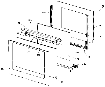
- figure 1 is a perspective exploded view of a door of an oven according to
the invention;
- figure 2 is a front view of the oven door of figure 1;
- figure 3 is a section view taken along line of figure 2; and
- figure 4 is an enlarged section view of a detail of the door of figures 1-
3 in the
configuration installed on a built-in oven.
With reference to the drawings, a door 10 of a built-in oven B comprises a
frame 12
composed of a U-shaped element 12a and of a rectilinear upper hollow element
12b
fixed to the upper ends of two vertical profiles 14 being part of the U-shaped
element
12a. The upper hollow element 12b may be made of polymeric material, for
instance an
engineering polymer. On the front and rear face of the frame 12 (with
reference to the
usual working configuration of the door 10 installed on the oven B) are fixed,
in a known
manner, an external and an internal glass plate respectively 16 and 18.
Between these
two glass plates 16 and 18, and an intermediate glass plate 20 is installed in
the frame
12, at a predetermined distance from the external glass plate 16 and from the
internal
glass plate 18 respectively. For maintaining such predetermined distance the
upper
hollow element 12b is provided with comb-shaped portions 24 in which the upper
edge
of the intermediate glass plate 20 is inserted. Similarly, in the lower
portion of the door,
between the external glass plate 16 and the internal glass plate 18 there are
positioned
spacer elements 26 (figures 1 and 3). On the external glass plate 16 a
decorative
rectangular frame 28 is fixed, for instance by means of an adhesive. It is
clear from the
above that the "sandwiched" assembly of the frame 12 with the glass plates 16,
18 and
20 defines a closed insulated wall which prevents the external glass plate 16
from
reaching high temperatures when the oven is used, particularly during the
pyrolitic cycle
thereof.
According to the invention, the upper hollow element 12b of the frame 12
presents a
front aperture 30 and it comprises an upper U-shaped rectilinear portion 32
which define

CA 02657825 2015-11-20
3
a front edge 32a which is used as an handle by the user. The rear portion of
the U-
shaped portion 32 presents a plurality of apertures 32b in form of slots which
are facing
an inlet (or outlet) opening V of the ventilation system of the oven B. The
upper hollow
element 12b of the frame 12 presents a lower portion 34 with a curved surface
34a
which has the function not only of defining a hollow space H for the fingers
of the user
when he/she wants to open the door 10, but also as part of the ventilation
system for
conveying an air flow towards the inlet opening V without a sensible pressure
drop.
According to the air passage across the upper hollow element 12b defining the
handle
of the door, the gap G (figure 4) between a control panel P of the oven B and
the upper
edge of the door 10 can be kept very low, i.e. the minimum distance sufficient
for
compensating mounting tolerances of the door 10 on the oven structure. At the
same
time the air flow across the upper hollow element 12b maintains the
temperature of the
"handle" at very low levels, close to the ambient temperature.
In the embodiment shown in the drawings, the upper hollow element 12b is flush
with
the outside surface of the door 10, therefore providing an even surface which
is very
easy to be cleaned by the user.
Even if in the described example the upper hollow element 12b is shown as an
elongated member, the actually hollow portion of such element can be reduced
in length
without departing from the scope of the present invention.

Representative Drawing
A single figure which represents the drawing illustrating the invention.
Administrative Status

2024-08-01:As part of the Next Generation Patents (NGP) transition, the Canadian Patents Database (CPD) now contains a more detailed Event History, which replicates the Event Log of our new back-office solution.

Please note that "Inactive:" events refers to events no longer in use in our new back-office solution.

For a clearer understanding of the status of the application/patent presented on this page, the site Disclaimer , as well as the definitions for Patent , Event History , Maintenance Fee  and Payment History  should be consulted.

Event History

Description Date
Time Limit for Reversal Expired 2019-03-11
Letter Sent 2018-03-12
Change of Address or Method of Correspondence Request Received 2018-01-12
Grant by Issuance 2016-10-04
Inactive: Cover page published 2016-10-03
Inactive: Final fee received 2016-08-24
Pre-grant 2016-08-24
Notice of Allowance is Issued 2016-03-17
Letter Sent 2016-03-17
Notice of Allowance is Issued 2016-03-17
Inactive: Approved for allowance (AFA) 2016-03-15
Inactive: Q2 passed 2016-03-15
Amendment Received - Voluntary Amendment 2015-11-20
Inactive: S.30(2) Rules - Examiner requisition 2015-06-09
Inactive: Report - No QC 2015-06-03
Letter Sent 2014-02-27
Request for Examination Requirements Determined Compliant 2014-02-19
All Requirements for Examination Determined Compliant 2014-02-19
Request for Examination Received 2014-02-19
Application Published (Open to Public Inspection) 2009-10-10
Inactive: Cover page published 2009-10-09
Inactive: IPC assigned 2009-08-27
Inactive: First IPC assigned 2009-08-27
Inactive: IPC assigned 2009-08-27
Inactive: Declaration of entitlement - Formalities 2009-04-29
Reinstatement Requirements Deemed Compliant for All Abandonment Reasons 2009-04-07
Inactive: Filing certificate - No RFE (English) 2009-04-06
Filing Requirements Determined Compliant 2009-04-06
Application Received - Regular National 2009-04-06

Abandonment History

There is no abandonment history.

Maintenance Fee

The last payment was received on 2016-02-05

Note : If the full payment has not been received on or before the date indicated, a further fee may be required which may be one of the following

  • the reinstatement fee;
  • the late payment fee; or
  • additional fee to reverse deemed expiry.

Please refer to the CIPO Patent Fees web page to see all current fee amounts.

Fee History

Fee Type Anniversary Year Due Date Paid Date
Application fee - standard 2009-03-11
MF (application, 2nd anniv.) - standard 02 2011-03-11 2011-02-11
MF (application, 3rd anniv.) - standard 03 2012-03-12 2012-03-07
MF (application, 4th anniv.) - standard 04 2013-03-11 2013-02-27
Request for examination - standard 2014-02-19
MF (application, 5th anniv.) - standard 05 2014-03-11 2014-02-26
MF (application, 6th anniv.) - standard 06 2015-03-11 2015-02-25
MF (application, 7th anniv.) - standard 07 2016-03-11 2016-02-05
Final fee - standard 2016-08-24
MF (patent, 8th anniv.) - standard 2017-03-13 2017-02-15
Owners on Record

Note: Records showing the ownership history in alphabetical order.

Current Owners on Record
WHIRLPOOL CORPORATION
Past Owners on Record
CRISTINA MAZZETTI
MARCO GIULIANI
MICHELE VENEZIA
Past Owners that do not appear in the "Owners on Record" listing will appear in other documentation within the application.
Documents

To view selected files, please enter reCAPTCHA code :


To view images, click a link in the Document Description column. To download the documents, select one or more checkboxes in the first column and then click the "Download Selected in PDF format (Zip Archive)" or the "Download Selected as Single PDF" button.

List of published and non-published patent-specific documents on the CPD .

If you have any difficulty accessing content, you can call the Client Service Centre at 1-866-997-1936 or send them an e-mail at CIPO Client Service Centre.


Document
Description 
Date
(yyyy-mm-dd) 
Number of pages   Size of Image (KB) 
Abstract 2009-03-11 1 13
Drawings 2009-03-11 3 83
Description 2009-03-11 3 133
Claims 2009-03-11 1 38
Representative drawing 2009-09-17 1 14
Cover Page 2009-09-29 1 38
Description 2015-11-20 3 130
Claims 2015-11-20 1 30
Drawings 2015-11-20 3 47
Cover Page 2016-09-08 1 39
Representative drawing 2016-09-08 1 13
Filing Certificate (English) 2009-04-06 1 156
Reminder of maintenance fee due 2010-11-15 1 113
Reminder - Request for Examination 2013-11-13 1 117
Acknowledgement of Request for Examination 2014-02-27 1 177
Commissioner's Notice - Application Found Allowable 2016-03-17 1 161
Maintenance Fee Notice 2018-04-23 1 178
Correspondence 2009-04-06 1 14
Correspondence 2009-04-29 2 40
Fees 2011-02-11 1 34
Amendment / response to report 2015-11-20 17 605
Final fee 2016-08-24 1 49