Note: Descriptions are shown in the official language in which they were submitted.
CA 02658162 2013-12-27
SELECTIVE AGITATION OF DOWNHOLE APPARATUS
FIELD OF THE INVENTION
This invention relates to an apparatus and method for use in the selective
agitation of
downhole apparatus. In particular, but not exclusively, the invention relates
to the selective
agitation of a drill string or a portion of a drill string, and the selective
agitation of a bottom
hole assembly (BHA).
BACKGROUND OF THE INVENTION
In the oil and gas industry, bores are drilled to access sub-surface
hydrocarbon-
bearing formations. Conventional drilling involves imparting rotation to a
drill string at
surface, which rotation is transferred to a drill bit mounted on a bottom hole
assembly (BHA)
at the distal end of the string. However, in directional drilling a downhole
drilling motor may
be used to impart rotation to the drill bit. In such situations it tends to be
more difficult to
advance the non-rotating drill string through the drilled bore than is the
case when the entire
length of drill string is rotating. The applicant supplies an apparatus, under
the AG-itator trade
mark, which may be utilised to induce vibration or movement to parts of a
drill string, and
which apparatus has been found to increase the rate of progress (ROP) of drill
bits during
some directional drilling operations. Features of this apparatus and other
tools capable of
inducing vibration or agitation may be found in applicant's US Patent Nos
6,279,670,
6,508,317 and 6,439,318.
Applicant's AG-itator apparatus includes a Moineau principle positive
displacement
motor (PDM). As drilling fluid pumped through the drill string drives the
motor, the motor
stator drives a valve arrangement to vary the flow of fluid through the lower
end of the drill
string. The varying or pulsing fluid flow acts on a shock-sub which tends to
extend and retract
in response to the pressure variations in the fluid in the string resulting
from the operation of
the valve.
SUMMARY OF THE INVENTION
According to the present invention there is provided a method of inducing
movement
in downhole apparatus, the method comprising:
1
CA 02658162 2009-01-06
WO 2008/007066 PCT/GB2007/002553
pumping fluid through a downhole support having a fluid actuated tool and a
downhole apparatus mounted thereon; and
selectively activating the fluid actuated tool to induce movement of the
downhole
apparatus.
According to another aspect of the invention there is provided a fluid
actuated
downhole tool for inducing movement of a downhole apparatus, the tool
comprising: a
body for coupling to downhole apparatus, the body being adapted to accommodate
flow
of fluid therethrough and including a flow-modifying arrangement for modifying
the flow
of fluid through the body to induce movement of the apparatus, the flow-
modifying
arrangement being configurable in an inactive configuration and in an active
configuration.
The downhole apparatus may be a BHA, a drill string, part of a drill string,
or
another downhole support or tubular, such as coil tubing or a casing string.
In use, embodiments of the invention allow fluid to be passed through a
downhole
support, such as a drill string, without inducing movement of the drill string
or of
apparatus mounted on the string. However, when desired, the flow modifying
arrangement of the fluid actuated tool may be configured or activated such
that the flow
of fluid induces movement of the downhole apparatus. This may be useful in a
number
of situations, for example at stages in certain drilling operations it may be
desirable to
agitate the BHA while at other times it may be desirable to avoid movement or
agitation
of the BHA.
Furthermore, an agitating tool will create a flow restriction and an
associated
pressure drop in the drill string. In some, but not all cases, it may be
possible to
accommodate this pressure drop by providing a higher fluid pressure above the
tool.
Additionally, some agitators can only accommodate a limited flow rate or
pressure of
fluid and thus the presence of an agitator in the string may limit the flow
rate or pressure
of fluid which may be pumped through the string. Embodiments of the invention
may
feature a flow diverter which selectively diverts flow around the flow-
modifying
arrangement such that the arrangement is not actuated, and the pressure drop
normally
associated with the operation of the arrangement is avoided. Other embodiments
feature
arrangements which include parts or portions which may be moved between
operative
2
CA 02658162 2009-01-06
WO 2008/007066 PCT/GB2007/002553
and non-operative configurations. Thus, it may be possible to configure the
downhole
tool such that the pressure drop or limitations apparent when the tool is
operating are
avoided or at least minimised when the tool is in the inactive configuration.
Inducing movement or agitation in a drill string may also only be desirable in
certain limited circumstances during a drilling operation. For example, if a
drill string
experiences differential sticking, inducing movement of the BHA or distal end
of the
string may be useful in freeing the string. To this end, it is known to
include jars in drill
strings for use in overcoming differential sticking, though the operation of a
jar requires
some time and only produces a single large impulse or shock. In contrast,
embodiments
of the present invention may be activated and actuated relatively quickly and
it is
believed the resulting agitation or vibration is more effective in freeing a
differentially
stuck string than the operation of a jar alone. Also, where a flow modifying
arrangement
is being utilised, this will induce pressure variations in the return flow of
fluid in the
annulus and may result in the annulus pressure falling below or close to the
formation
pressure, thus reducing or negating the difference in pressure between the
annulus and
formation which induced the differential sticking. Of course embodiments of
the present
invention may be provided in conjunction with ajar.
A plurality of fluid actuated tools in accordance with embodiments of the
invention may be provided in a drill string. The tools may be adapted to be
activated in
unison, or may be activated and deactivated individually. Thus, movement of
selected
parts of a string may be induced, which may be useful where a particular
section of the
string is differentially stuck.
The downhole tool may take any appropriate form. In one embodiment, the tool
includes a valve arrangement for use in modifying fluid flow. The valve
arrangement
may include relatively movable cooperating valve members. The valve members
may
move relative to one another in any appropriate manner, for example axially,
laterally, or
may rotate. In one embodiment the valve members are in the form of valve
plates or
members which are relatively rotatable and laterally movable.
Activation and
deactivation of the tool may be achieved by modifying the valve arrangement.
The valve
arrangement may be inactivated by fixing or otherwise retaining valve members
relative
to one another, typically in an open configuration by translating one or more
valve
3
CA 02658162 2009-01-06
WO 2008/007066 PCT/GB2007/002553
members to non-operative positions, for example axially separating valve
members, or by
arranging for bypass of the valve arrangement.
Alternatively, or in addition, the tool may include a drive arrangement for
driving
the valve arrangement, and removing or decoupling drive from the valve
arrangement
may inactivate the tool. The drive arrangement may be fluid actuated, and the
tool may
be activated by directing fluid flow through the drive arrangement, and
inactivated by
bypassing the drive arrangement. This offers the advantage that pressure
losses and wear
and tear associated with the operation of the drive arrangement are avoided
while the tool
is inactive. Also, any limitations of the drive arrangement, for example
pressure or flow
rate restrictions, may be ignored while the tool is inactive, providing the
operator with
greater freedom and not placing restrictions on other operations. The drive
arrangement
may take any appropriate form, and may be a positive displacement motor (PDM),
such
as a Moineau principle motor. Where the drive arrangement includes a rotor or
other
moving part and a stator or other stationary part, the rotor may be translated
relative to
the stator to inactivate or render inoperative one or both of the drive
arrangement and the
valve arrangement. For example, axial movement of a rotor relative to a stator
may
inactivate the motor. If a valve member is coupled to the rotor, movement of
the rotor
relative to the stator may inactivate the valve arrangement. In a Moineau
principle motor,
axial movement of the rotor may be utilised to create an open axial flow path
through the
motor, such that the motor does not operate. Alternatively, in a Moineau
principle motor
with a valve member mounted to the rotor, limited axial movement of the rotor
may
render the valve arrangement inoperative, but may still result in rotation of
the rotor.
Movement of the rotor to an inoperative position may be induced by application
of
mechanical force, for example tension or weight, or by fluid pressure, which
fluid
pressure may be flow-related or may be a differential pressure between the
interior of the
tool and the surrounding annulus. One advantage of continuing to direct fluid
through
one or both of an inoperative or inactive drive arrangement and a valve
arrangement is
that this avoids the requirement to accommodate bypass flow within the tool
body. Thus,
the drive arrangement may occupy a larger cross-section and may be able to
handle
higher pressures and flow rates, and provide movement or vibrations of greater
magnitude.
4
CA 02658162 2009-01-06
WO 2008/007066 PCT/GB2007/002553
In other embodiments the drive arrangement may be omitted, for example an
unstable valve arrangement may be provided which is adapted to shuttle or
change
configuration in certain conditions, for example when exposed to selected flow
rates or
pressures. When exposed to other conditions, the valve arrangement may assume
a stable
or inactive configuration. In one embodiment the fluid flow rates and
pressures
associated with normal drilling operations will maintain the valve arrangement
in a stable
open configuration. However, at a predetermined lower flow rate and pressure
the valve
assumes an unstable position and shuttles between the open and closed
configurations.
Where the tool includes a bypass arrangement this may take any appropriate
form.
The bypass arrangement may include a bypass valve, which may be configured to,
for
example, direct fluid away from a flow modifying valve arrangement or a drive
arrangement and through a bypass conduit. The bypass arrangement may be
actuated by
any appropriate means, and in certain embodiments is fluid pressure actuated,
but may
alternatively be actuated by mechanical force, for example by tension or
weight.
The tool may be normally active, or normally inactive, and may be configured
such that the tool maintains the desired, normal configuration during selected
operational
conditions, for example while the tool experiences the pressures and flow
rates associated
with normal drilling operations. However, if selected parameters change, for
example the
fluid flow rate or pressure increases, the tool may be adapted to assume the
alternative
configuration. In another embodiment, in a drilling application, the tool will
be normally
inactive when the tool is in compression, associated with weight being applied
through
the string from surface to the drill bit. However, if tension is applied to
the string and the
tool, associated with tension being applied to overcome a differential
sticking problem, a
predetermined tension may result in the tool assuming the active
configuration, such that
the drill string may be agitated while tension is applied from surface. The
tool may be
biased to assume the normal configuration by a spring.
The tool may be provided in combination with a fluid pressure-responsive tool,
such as a shock tool. Thus, changes in the flow through the tool induce
changes in the
fluid-pressure responsive tool which may, for example, tend to axially extend
and
contract in response to changes in fluid pressure. The changes in the fluid
responsive-
tool may induce vibration or agitation of the associated downhole apparatus.
In certain
CA 02658162 2014-10-24
applications the presence of a fluid pressure-responsive tool may provide an
enhanced
agitation effect. The fluid pressure responsive tool may also be coupled or
otherwise
associated with one or both of a valve arrangement and a drive arrangement,
whereby
application of tension to the fluid pressure responsive tool may alter the
configuration of
a valve arrangement or drive arrangement, or may direct fluid to bypass one or
both of the
valve and drive arrangements. However, in certain downhole applications, for
example
where the downhole apparatus is coil tubing-mounted, the fluid pressure-
responsive tool
may be omitted: the relatively flexible coil tubing will itself tend to extend
and contract
on exposure to varying pressure.
According to another aspect of the present invention there is provided a
method of
inducing agitation in downhole apparatus, the method comprising:
pumping fluid through a downhole support having a fluid actuated tool and a
downhole apparatus mounted thereon; and
selectively activating the fluid actuated tool from the surface by varying an
operating condition which causes, when desired, a flow modifying arrangement
of the
fluid actuated tool to be activated such that the flow of fluid through the
tool creates
pressure pulses as it flows through the activated flow-modifying arrangement
to induce
agitation of the downhole apparatus.
According to a further aspect of the present invention there is provided a
fluid
actuated downhole tool for inducing agitation of a downhole apparatus, the
tool
comprising:
a body for coupling to downhole apparatus, the body being adapted to
accommodate flow of fluid therethrough and including a flow-modifying
arrangement for
modifying the flow of fluid through the body, the flow-modifying arrangement
being
configurable in an inactive configuration and in an active configuration;
6
CA 02658162 2014-10-24
wherein the fluid actuated tool is selectively operated from the surface by
varying
an operating condition which causes, when desired, the flow modifying
arrangement of
the fluid actuated tool to be activated and be operable to create pressure
pulses such that
the flow of fluid through the flow through the activated flow-modifying
arrangement of
said tool induces agitation of the downhole apparatus.
According to a further aspect of the present invention there is provided an
apparatus comprises a plurality of fluid actuated tools as described herein,
wherein the
tools are provided in a drill string.
BRIEF DESCRIPTION OF THE DRAWINGS
These and other aspects of the invention will now be described, by way of
example, with reference to the accompanying drawings, in which:
Figures 1, 2 and 3 are sectional drawings of a downhole tool for inducing
movement of a downhole apparatus in accordance with a first embodiment of the
present
invention;
Figures 4, 5 and 6 are sectional drawings of a downhole tool for inducing
movement of a downhole apparatus in accordance with a second embodiment of the
present invention;
Figure 7 is a sectional drawing of a downhole tool for inducing movement of a
downhole apparatus in accordance with a third embodiment of the present
invention; and
Figures 8 and 9 are sectional drawings of a downhole tool for inducing
movement
of a downhole apparatus in accordance with a fourth embodiment of the present
invention.
DETAILED DESCRIPTION OF THE DRAWINGS
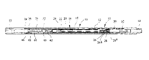
Reference is first made to Figures 1, 2 and 3 of the drawings, which are
sectional
drawings of a fluid actuated downhole tool 10 for inducing movement of a
downhole
apparatus in accordance with a first embodiment of the present invention. The
tool 10 is
adapted to be incorporated in a drilling fluid transmitting drill string and
thus includes a
6a
CA 02658162 2013-12-27
generally cylindrical hollow body 12 featuring conventional pin and box
connections 14, 15 at
the lower and upper ends of the body.
As noted above, the tool 10 is adapted to permit passage of drilling fluid
and, as will
be described, in selected tool configurations fluid may pass through the tool
10 without
actuating the tool. However, in an alternative configuration the drilling
fluid is directed
through the tool 10 to actuate the tool 10, creating pressure pulses in the
drilling fluid which
may be utilised to agitate or vibrate the tool string to, for example,
overcome differential
sticking problems.
The tool 10 comprises a drilling fluid-flow modifying valve 15 and an
associated drive
motor 16, both accommodated within a central portion of the tool body 12. The
motor is
Moineau principle positive displace motor comprising a central rotor 18 which
rotates within a
stator 20 comprising a profiled elastomeric stator body 22 located within a
metallic tubular
stator housing 24. The lower end of the rotor 18 extends beyond the stator 20
and provides
mounting for a moveable valve member 26 which co-operates with a fixed valve
member 28.
When the motor 16 is operating, the rotor 18 rotates and also moves
transversely, and this
movement is transferred to the rotor-mounted valve member 26. The movement of
the valve
member 26 moves the respective valve openings 26a, 28a into and out of
alignment, to vary
the open flow area defined by the valve 15.
The motor 16 does not occupy all of the area defined within the tool body 12,
and an
annular bypass passage 32 is provided between the stator housing 24 and the
tool body 12. A
bypass passage inlet 34 is formed between a bypass control collar 36, which is
spring mounted
on the tool body 12, and a tubular stator extension 38 provided on the upper
end of the stator
housing 24. Fluid passage through the tubular extension 38, and into the motor
16, is also
controlled, in part, by a valve 40 provided within the stator extension 38. A
light spring 42
normally maintains the valve 40 in the closed position.
As noted above, the collar 36 is mounted in the tool body 12, and is normally
biased
towards an upper position by a spring 44. The lower end of the collar 36
defines an inwardly
extending lip 46. The outer diameter of the extension 38 also defines a lip
48, and when the
lips 46, 48 are aligned, as shown in Figure 2 of the drawings, flow
CA 02658162 2009-01-06
WO 2008/007066 PCT/GB2007/002553
through the bypass passage inlet 34 is restricted, and thus the drilling fluid
flow will be
directed through the motor 16.
The collar 36 is configured such that, in the absence of any through flow, or
in the
presence of a flow rate through the tool 10 up to a predetermined level, the
spring 44
maintains the collar in an upper position, with the collar lip 46 located
above and spaced
from the extension lip 48, as illustrated in Figure 1. However, with an
elevated flow rate,
the pressure differential across the collar 36 increases, and the collar 36 is
pushed
downwardly, against the action of the spring 44, to locate the lips 46, 48
directly adjacent
one another, so as to restrict the passage of fluid into the bypass passage
32, as illustrated
in Figure 2. This would normally be the stop position for the collar 36.
However, in
certain embodiments, a still further increase in flow rate will push the
collar 36 to a lower
position in which the collar lip 46 is located spaced from and below the
stator extension
lip 48, allowing fluid to flow through the bypass passage 32 once more, as
illustrated in
Figure 3.
A bypass passage outlet 50 is defined by lateral passages formed in a tubular
support 52 which mounts the motor 16 to the body 12.
In use, the tool 10 is incorporated in a drill string at an appropriate
location,
typically just above the BHA, and below a shock tool. When the drilling fluid
pumps are
running up to and at their normal operational pressure, the bypass control
collar 36 is
located as illustrated in Figure 1 to open the bypass inlet 34, such that
drilling fluid may
flow through the bypass passage 32. Thus, the drilling fluid does not pass
through the
motor 16, and there is no agitation produced.
However, if the pump pressure is increased, the pressure differential created
across the collar 36 also increases and the collar 36 is pushed downward,
against the
action of the spring 44, to align the lips 46, 48, and substantially restrict
access to the
bypass passage 32. The motor valve 40 now experiences an elevated differential
pressure, and thus opens (as illustrated in Figure 2) to allow the drilling
fluid to flow into
and through the motor 16.
The flow of fluid through the motor 16 causes the rotor 18 to rotate and thus
drives the valve member 26, varying the open flow area defined by the valve
15. The
resulting variation in flow area creates pressure pulses within the string,
which pulses act
8
CA 02658162 2009-01-06
WO 2008/007066 PCT/GB2007/002553
on the shock tool provided in the string above the tool 10. The shock tool
tends to extend
and retract in response to the pulses. The combined effect of the pulsing
fluid pressure in
the string and the extension and retraction of the shock sub cause agitation
and vibration
of the string which may be utilised to, for example, assist in overcoming
differential
sticking problems.
When agitation of the string is no longer required, the flow of drilling fluid
is
decreased, such that the bypass control collar 36 moves upwards to misalign
the lips 46,
48, allowing access to the bypass passage 32. The spring 42 then closes the
motor valve
40, such that the drilling fluid will bypass the motor 16 once more, and
drilling
operations may continue in the absence of agitation.
Reference is now made to Figures 4, 5 and 6 of the drawings, which illustrate
a
tool 110 in accordance with a second embodiment of the present invention. The
tool 110
shares many features with the tool 10 described above, but is reconfigured,
between an
active or agitating configuration and an inactive or non-agitating
configuration, by
mechanical force, in particular by application of weight and tension.
Figure 4 illustrates a shock tool 160, the shock tool female body portion 162
being fixed to the upper end of the tool body 112. The shock tool male body
portion 164
is coupled to a sleeve 166 which is slidably coupled to the upper end of the
stator
extension 138.
In this embodiment, the tool body 112 defines the inwardly directed bypass
control lips 146, whereas the stator extension 138 defines the outwardly
directed lips 148.
Lateral flow passages 168 are provided in the sleeve 166 above the lips 148.
In use, the tool 110 and shock tool 160 are incorporated in a drill string.
During
drilling, with weight being applied through the string to the bit, the shock
tool 160 is
compressed, compressing the spring 170 between the male and female shock tool
portions 164, 162, such that the stator extension lips 148 are located spaced
from and
below the lips 146, as illustrated in Figure 4. Thus, drilling fluid may pass
through the
shock sub, through the sleeve 166 and into the bypass passage 132 via the flow
passages
168.
However, if tension is applied to the string, the shock tool 160 is axially
extended
and the male and female shock tool parts 164, 162 are moved relative to one
another such
9
CA 02658162 2009-01-06
WO 2008/007066 PCT/GB2007/002553
that the lips 146, 148 are aligned. Fluid flow is thus now directed through
the motor 116,
to provide agitation. Still further tension may result in the tool 110
assuming the
configuration as shown in Figure 6, in which the bypass passage 132 is re-
opened and the
motor valve 140 closed.
Reference is now made to Figure 7 of the drawings, which illustrates a tool
210 in
accordance with a third embodiment of the present invention. This tool 210
shares many
features with the above-described tool 110. However the operating parts of the
tool 210
are not mounted directly to the tool body 212, but are rigidly coupled to the
shock sub
male body portion 264 by a stator extension 238 which defines lateral flow
passages 268
and an outwardly extending lip 248. Thus, when weight is applied to a drill
bit from
surface via a drill string incorporating the tool 210, the motor 216 assumes
the position
within the tool body 212 as illustrated in Figure 7, such that the drilling
fluid may bypass
the motor 216 and valve 215. However, if tension is applied to the string the
bypass
passage 232 is closed by the alignment of the lips 246, 248, and drilling
fluid will be
directed through the motor 216, and the valve 215 driven to provide vibration
and
agitation of the drill string.
Figures 8 and 9 of the drawings illustrate a tool 310 in accordance with a
fourth
embodiment of the invention. In this tool 310 there is no provision for bypass
of the
motor 316. Rather, as will be described, the tool 310 is inactivated by
separating the
valve members 326, 328.
In the absence of a bypass passage, the tool body 312 also forms the motor
body,
allowing the tool 310 to incorporate a larger diameter motor 316, which motor
316 will
accommodate large flow rates and larger pressure differentials.
The motor rotor 318 is axially movable within the stator 320, such that the
valve
members 326, 328 may be spaced apart, as illustrated in Figure 8, or in an
abutting,
operative configuration, as shown in Figure 9. Clearly, when the valve member
326, 328
are spaced apart, rotation of the movable valve member 326 will have no impact
on the
flow of drilling fluid through the tool 310.
Axial movement of the rotor 318 is achieved by operation of a fluid flow-
actuated
stator adjuster 370 located in an upper portion of the tool body "310. The
adjuster 370
includes a flow sleeve 372 which is coupled to the rotor 318 by a stator
extension 374,
CA 02658162 2009-01-06
WO 2008/007066 PCT/GB2007/002553
the coupling between the sleeve 372 and the extension 374 being adapted to
accommodate the rotation and transverse movement of the rotor 318.
The lower end of the sleeve 372 defines restricted flow outlets 376, such that
pumping drilling fluid through the sleeve 372 creates a downwardly directed
differential
fluid pressure force on the sleeve 372, which force is resisted by a
compression spring
378 provided between the sleeve 372 and the tool body 312.
At lower flow rates, the spring 378 maintains the valve members 326, 328 in a
spaced apart configuration, as illustrated in Figure 8. The motor 316 is
actuated by the
flow of fluid through the string, however the corresponding rotation of the
valve member
326 has no impact on the flow of fluid through the valve 315, such that there
is no
agitation of the string.
At higher flow rates, the sleeve 372 is pushed downwards such that the valve
315
assumes an operative configuration, as illustrated in Figure 9. In this
configuration,
rotation of the valve member 326 varies the flow area through the valve 315,
producing
agitation of the drill string.
Thus, the operation of the tool 310, and thus the absence or presence of
vibration
or agitation, may be controlled merely by varying the rate at which drilling
fluid is
pumped through the drill string.
Thus, it will be apparent to the person of skill in the art that the various
embodiments of the present invention descried above provide the operator with
a
convenient means of selectively agitating a drill string,
Those of skill in the art will also appreciate that the above-described
embodiments
are merely exemplary of the present invention and that various modifications
and
improvements may be made to these embodiments without departing from the scope
of
the invention. For example, tools made in accordance with embodiments of the
invention
could be used in other combinations with other tubing forms, such as coil
tubing or a tool
string.
11