Note: Descriptions are shown in the official language in which they were submitted.
CA 02658205 2014-09-18
- 1 -
METHOD FOR DETERMINING
PHYSICAL PROPERTIES OF STRUCTURES
[00011
FIELD OF THE INVENTION
[0002] This invention relates generally to the field of geophysical
prospecting
and, more particularly, to electromagnetic prospecting. Specifically, the
invention is an
efficient method for inverting controlled-source electromagnetic data to
obtain a
subsurface resistivity data volume, wherein subsurface structures are
identified from
pre-existing high resolution survey data such as seismic data, and this
geometric
information is used to define cells in an inversion computational grid having
fewer cells
than the mesh used for forward modeling.
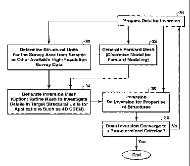
BACKGROUND OF THE INVENTION
[0003] The most widely used techniques for geological surveying and
hydrocarbon exploration are seismic methods. The seismic methods can image the
structures of the sub-seafloor strata and reveal the location and shape of a
potential
reservoir, but face well documented difficulties in determining reservoir
saturation.
Conventionally, the solution to this is to drill a borehole into the
reservoir. The costs of
drilling a borehole offshore are expensive, often in tens of million dollars.
Very
recently, electromagnetic methods, for example controlled source
electromagnetic
methods ("CSEM") and magnetotellurics ("MT"), have been developed for
determining or mapping sub-seafloor resistivity variations. See, for example,
U.S.
Patent No. 6,603,313 to Srnka. While seismic properties of hydrocarbon-filled
and
water-filled reservoirs do not differ significantly, their electromagnetic
properties can
be significantly different. For example, the resistivity difference between
the two
cases can be up to two orders in magnitude. Electromagnetic ("EM") methods
exploit
CA 02658205 2009-01-15
WO 2008/013613 PCT/US2007/013854
- 2 -
these differences to predict the nature of a reservoir and save cost in
hydrocarbon
exploration. EM data inversion provides a technology to realize this
exploitation in
hydrocarbon exploration.
[0004] Geophysical data inversion is a procedure for obtaining earth
models
that satisfy measured data sets. The inversion process can provide physically
meaningful information concerning both rock properties and earth structure,
and
therefore is a useful tool for the earth scientists. Inversion has been
applied in global
seismology, exploration seismic, potential field, and electromagnetic
exploration.
See, for example, Inversion of GeOphysical Data, L.R. Lines, Ed., Society of
Exploration Geophysicists (1988). 3D inversion of EM data can provide unique
information related to reservoir location, shape and fluid properties.
However, current
3D EM inversion schemes require expensive computer resources even to obtain
low-
resolution images.
[0005] The inversion process is closely related to forward modeling.
Forward
modeling uses a mathematical relationship (Maxwell's electromagnetic field
equations. for CSEM and MT) to simulate the earth's response for a given set
of model
parameters. Forward modeling can be written symbolically as d = F(m), where
(for
electromagnetic problems) m is a model of the earth's resistivity, F is known
from
Maxwell's equations for the EM fields, and d is a vector of response of the
model in.
Forward modeling provides a means to compute d for any model in. The inverse
problem corresponding to this forward problem would be to find the set of all
m that
yield the given data d (a field or synthetic data set for inversion). It may
be written,
again symbolically, as in= F-1(d). This inverse operator F`' is nonlinear,
very
complicated and non-unique for EM inversion. A simple and computationally
tractable approach to the nonlinear multi-dimensional inverse problem is the
linearized inversion. The nonlinear relationship between data and model in the
forward problem is approximated by d = F(nio) + Gm. The model update Sin to a
known (or guessed) model mo can be obtained by solving a linear system G8in =
b,
where G is the Jacobian matrix and b = d F(mo) is the data residual. The model
can be updated iteratively by adding Om to mo until a satisfactory fit to the
data has
CA 02658205 2009-01-15
WO 2008/013613 PCT/US2007/013854
- 3 -
been obtained. The inverse problem and its solutions have been studied
extensively
(see, for example, R. L. Parker, Geophysical Inverse Theory (1994); W. Menke,
Geophysical Data Analysis: Discrete Inverse Theory (1989); and A. Tarantola,
Inverse Problem Theory, (1987)).
[0006] There are at least four major problems with EM inversions: The
first
problem is that many solutions are acceptable for inversion from a
mathematical
viewpoint (i.e., the non-uniqueness problem), especially when the data are
limited and
inaccurate. Mathematical approaches such as regularization are often
implemented in
inversion to mitigate some aspects of non-uniqueness. The second problem with
multi-dimensional inversion is the cost. The linear equation system resulting
from
linearization is often very large for a multi-dimensional problem and requires
the use
of a supercomputer or massively paralleled computer system, particularly for
CSEM
data inversion. Newman and Alumbaugh inverted a synthetic data set of 12,600
source-receiver pairs with 1 frequency for a moderate 3D model with 29,971
cells.
The processing time needed to produce a useful image was approximately 31
hours on
the 1728-processor Intel Paragon, with 512 processors utilized (Newman and
Alumbaugh, "Three-dimensional massively parallel electromagnetic inversion ¨
I.
Theory," Geophys. J. mt. 128, 345-354 (1997)). It could take over a month to
invert a
large EM field data set for a large 3D model even on modern massively-parallel
machines, which therefore limits 3D EM inversion application. The third
problem
with EM inversion is related to inversion resolution. Due to the diffusive
nature of
the EM field at low frequency, the resolution provided by EM is very low and
cannot
compete with seismic resolution. In general, a highly simplified picture (a
blurred
image) of 3D structures is all that can be obtained for EM inversion (West and
Macnae, "Physics of Electromagnetic Induction Exploration Method," in
Electromagnetic Methods in Applied Geophysics (ed. M.N. Nambighian), Vol. 2, 5-
45, Society of Exploration Geophysicists (1987)).
[0007] The fourth problem is related to model discretization in
numerical
modeling. Both multi-dimensional forward modeling and inversion are normally
based on a discretized model. Discretization depends on the employed numerical
CA 02658205 2009-01-15
WO 2008/013613 PCT/US2007/013854
- 4 -
modeling method (for example, the finite difference method, the integral
equation
method, the finite element method, or other method). Features and requirements
on
discretization for each method can easily be found in numerical modeling
books. In
principle, in order to model fine structures and achieve accurate forward
modeling
results, the model needs be discretized finely enough. Figure 1 shows a
uniform
rectangular grid which is preferred for the finite difference method. This
same fine
discretization is typically used for both forward and inversion. That is,
numerical
methods of iteratively solving the inversion problem necessarily involve
forward
modeling at each iteration step, and it is typical to use the same discrete
grid for each.
The use of fine discretization in the inverse process has adverse effects: (1)
it
generates a huge system of linear equations (specially for the finite
difference
method), which needs a lot of computer resources for a reasonable turn-around
time;
(2) it may woisen the non-uniqueness because EM methods cannot resolve a small
cell at depth due to lack of sensitivity (For example, cell j in Fig. 1). From
another
viewpoint, the contributions to response due to source TX measured at receiver
RX
from cell i at shallow depth and a deeper lying cell j of the same size are
significantly
different. In other words, receiver RX is much more sensitive to cell i than
to cell j.
Therefore, it is not optimal to treat them in the same way in inversion. The
inversion
non-uniqueness and the low EM resolution affect each other to make EM
inversion
much more challenging.
[0008] In reality, the unknown model m is a function of position, which
is of
infinite dimension, and the measurements d comprise only a finite collection
of
numbers with error, so that the inverse problem is not unique. As already
mentioned
non-uniqueness is a serious problem in inversion. A variety of approaches have
been .
proposed to deal with the non-uniqueness problem. One approach has been to
find
localized averages that are shared by all models that are close enough to some
reference model for a linearization approximation to hold (Backus and Gilbert,
"The
resolving power of gross earth data," Geophy. J. R. astr. Soc. 16, 169-205
(1968);
Parker, "The inverse problem of electromagnetic induction: existence and
construction of solutions based on incomplete data," J. Geophys. Res. 85, 4421-
4428
CA 02658205 2009-01-15
WO 2008/013613 PCT/US2007/013854
- 5 -
(1970); Oldenburg, 1979, "One dimensional inversion of natural source
magnetotelluric observations," Geophysics 44, 1218-1244 (1979)). A second
approach has been to find models minimizing some functional, particularly
functionals that penalize roughness of the model (Tikhonov and Arsenin,
Solutions of
ill-posed problems, John Wiley and Sons (1977); Parker, "The theory of ideal
bodies
for gravity interpretation," Geophy. J. R. astr. Soc. 42, 315-334 (1975);
Constable et
al., "Occam's inversion: a practical algorithm for generating smooth models
from EM
sounding data," Geophysics 52, 289-300 (1987); and Smith and Booker,
"Magnetotelluric inversion for minimum structure," Geophysics 53, 1565-1576
(1988)). A third approach has been to assume prior knowledge of the
distribution of
likely models and find which of these models is most likely given a set of
data
(Franklin, "Well-posed stochastic extensions of ill-posed problems," J. Math.
Anal.
Appl. 31, 682-716 (1970); and Jordan and Franklin, "Optimal solutions to a
linear
inverse problem in geophysics," Proc. Nat Acad. Sci. 68, 291-293 (1971)). A
fourth
approach (called joint inversion or cooperative inversion) has been to jointly
invert
various independent geophysical data sets (Vozoff and Jupp, "Joint inversion
of
geophysical data," Geophy. J. R. astr. Soc. 42, 977-991 (1974); Savino et al.,
"Simultaneous inversion of multiple geophysical data sets for earth
structure," SEG
45th Annual International Meeting (1980); Lines et al., "Cooperative inversion
of
geophysical data," Geophysics 53, 8-20 (1988); and Benech et al., "Joint
inversion of
EM and magnetic data for near-surface studies," Geophysics 67, 1729-1739
(2002)).
When dealing with specific or known structures derived from other geological
and
geophysical information, constrained inversion is employed to incorporate the
specific
structures into inversion. Wu incorporated structural constraints into model
by
inserting a discontinuous boundary within model; freezing the model at the
specific
nodes; and allowing different measures of model roughness in specified areas
("High
resolution electromagnetic image of conductivity structure in the mid-lower
crust and
upper mantle ¨ A magnetotelluric experiment conducted primarily in North
Dakota,"
Ph.D. Dissertation, Univ. of Washington (1994)). Structural information is
also
incorporated into seismic tomography (Grau and Lailly, "Sequential migration-
aided
reflection tomography: an approach to imaging complex structures," Journal of
CA 02658205 2009-01-15
WO 2008/013613 PCT/US2007/013854
- 6 -
Applied Geophysics 30; 75-87 (1993); Clapp, et al., "Incorporating geological
information into reflection tomography," Geophysics 69, 533-546 (2004)). The
first
three approaches use mathematic constraints to mitigate the non-uniqueness.
Such
constraints may not be consistent with the reality and therefore the inversion
may
provide an image inconsistent with the truth. The last two approaches use
physical
constraints from independent data sets which are consistent with the reality.
[0009] All of the preceding approaches result in a very large linear
system to
solve. Options to solve a very large linear system are very limited. A
powerful
computer is often needed in order to obtain results in a reasonable time.
Nevertheless,
a number of techniques have been developed to speed up computation at
different
stages of the inverse process. For example, more efficient optimization
techniques
such as non-linear conjugate gradient (NLCG) solver, multi-grid for modeling,
approximate computation for sensitivity matrix, reciprocity application for
source and
receiver configurations, etc. All those techniques are helpful, but more
improvements
are needed to make 3D EM inversion a routine practice with reasonable demand
on
computer resources.
[0010] Non-uniqueness and resolution affect each other. Theoretically,
the
mathematical approaches to the non-uniqueness problem do not provide new
information to enhance the resolution of a data set, rather than post
constraints on
model. However, they do affect the final image because of the implementation
of
mathematical constraints on the model. Joint inversion and constrained
inversion not
only mitigate the non-uniqueness but also enhance the resolution. Joint
inversion
results in a much larger linear system and therefore is more expensive to
apply in
practice. Even though constrained inversion utilizes some structural
information in
inversion, its inversion is still implemented to recover the geometry of
structures as
well as their physical properties. Therefore, the resolution provided by
constrained
EM inversion is largely limited by the diffusion nature of EM fields.
[0011] It is convenient and simple to use the same discretization in
implementation of both forward modeling and inversion. No techniques that deal
CA 02658205 2009-01-15
WO 2008/013613 PCT/US2007/013854
- 7 -
with the problem of using the fme discretization in inversion were found in EM
inversion publications. In seismic tomographic inversion, the matrix
transformation is
used in order to use non-uniform grids, which is better for constructing a
physical
property model of a subsurface region (PCT International Publication No.
W02007/0 18869).
[0012] The present invention provides a faster method for inverting EM
data
with lower demand on computer resources for physically constrained solutions
of high
resolution.
SUMMARY OF THE INVENTION
[0013] In one embodiment, the invention is a method for inverting
measured
data from a controlled-source electromagnetic survey of a subsurface region to
generate a resistivity data volume representing the subsurface region,
comprising:
(a) selecting a discrete forward-modeling grid to represent at least a
portion of the subsurface region;
(b) determining geometry information for structural units of the subsurface
region from seismic or other available data;
(c) generating an inversion grid with a mesh based on the structural unit
geometry, the inversion grid containing fewer cells than the forward modeling
grid;
(d) specifying an initial resistivity model of the portion of the
subsurface
region, said model having a value of resistivity for each cell in the
inversion grid;
(e) solving Maxwell's electromagnetic field equations on the forward-
modeling grid at one or more frequencies for a plurality of source-receivers
survey
positions, said frequencies being selected from the frequency spectrum of the
survey's
source waveform, said solution using survey source-receiver geometry
information
and source parameters and resistivity values from the resistivity model; and
CA 02658205 2009-01-15
WO 2008/013613 PCT/US2007/013854
- 8 -
(0 generating an adjusted resistivity model by comparing the
computed
electromagnetic field values to the measured survey data, said comparison
including
minimizing a selected objective function, thereby using differences between
computed
electromagnetic field values and measured survey data to determine resistivity
model
adjustments.
. [0014] In many applications., steps (e) and (f) will be repeated until a
pre-
selected convergence criterion or other stopping point is reached, replacing
the
resistivity model used in step (e) in each iteration. cycle by the adjusted
resistivity
model from step (f) of the previous cycle.
BRIEF DESCRIPTION OF THE DRAWINGS
[0015] The present invention and its advantages will be better
understood by
referring to the following detailed description and the attached drawings in
which:
Fig. 1 illustrates a typical fine scale discrete grid typically used for both
forward modeling and inversion;
Fig. 2 illustrates different model discretizations for inversion as compared
to
forward modeling;
Fig. 3 is a flow chart showing basic steps in one embodiment of the present
invention;
Figs. 4A-B show inverted results for different EM source frequencies using
conventional inversion techniques;
Figs. 5A-B show inverted results for different EM source frequencies using the
present inventive method;
Fig. 6 shows inverted results. at a single source frequency using the present
inventive method;
=
Fig. 7 shows an example section of seismic data; and
CA 02658205 2014-09-18
- 9 -
Fig. 8 shows structural units interpreted from the seismic profile of Fig. 7.
[0016] The invention will be described in connection with its preferred
embodiments. However, to the extent that the following detailed description is
specific
to a particular embodiment or a particular use of the invention, this is
intended to be
illustrative only, and is not to be construed as limiting the scope of the
invention. The
scope of the claims should not be limited by particular embodiments set forth
herein,
but should be construed in a manner consistent with the specification as a
whole.
DETAILED DESCRIPTION OF THE PREFERRED EMBODIMENTS
[0017] The present invention, takes advantage of different geophysical
data sets
to obtain a resistivity earth model of higher resolution than can be achieved
by one
data set alone. More specifically, the geometry information of the structures
is fully
determined/preset by other measurements and prior spatial information before
inversion, and therefore the measured EM data are inverted only for the
properties, i.e.
resistivities for EM inversion, of the predetermined structural units.
[0018] Traditionally, EM inversion is used to solve for both the geometry
information of structures (i.e. locations, shapes, etc) and their physical
properties (i.e.
resistivities). The present inventive method inverts EM data to recover only
the
physical properties of the structures by incorporating the geometry
information of the
structures obtained from other measurements such as seismic and logs, which
have
much higher resolution. When EM methods are applied to potential targets, the
targets
have typically been first determined and delineated by seismic survey. Seismic
data
can provide much finer scale information about the subterranean structures in
the
survey area than EM methods. Incorporating the structures from seismic and
other
surveys such as logs into EM data inversion greatly improves EM inversion in
resolution and reduces the problem of getting non-unique solutions. Once the
geometry
of the structures is set, the freedom of changing resistivities of the
structures to best fit
the EM data is dramatically decreased, i.e. the problem becomes much less
non-unique. By contrast, conventional constrained inversion techniques aim to
utilize
CA 02658205 2009-01-15
WO 2008/013613 PCT/US2007/013854
- 10 -
known information, but never to completely use other surveys with higher
resolution
for geometry information.
[0019] The present invention also separates the model discretization for
inversion from that for forward modeling. Figure 2 shows an example of
different
discretizations for forward modeling and inversion. A fine discretization, a
rectangular mesh in Fig. 2, is for forward modeling to accurately model EM
fields
everywhere. The irregular mesh (Twelve irregular shaped, much larger cells,
indicated by the different shadings) is for inversion. This inversion mesh
consists of
structural units determined by other geophysical measurements with high
resolution
such as seismic and logging. Currently a typical 3D EM inversion of a field
data set
has unknowns on the order of 106 if the same discretization is used. Units of
interpreted structures from seismic could be about 10 ¨ 103. The reduction in
unknowns (3 orders of magnitude or more) can significantly increase the
inversion
speed and require less computer resources, therefore low cost.
[0020] This method is flexible in order to include all structural units
including
those regarded as background. This will reduce error in inverted results
caused by
fixing background if the background is not determined accurately. The process
of
incorporating the geometry information of structures can be iterative. Figure
3 is a
flow chart showing basic steps in one embodiment of the invention.
[0021] At step 31, the measured data are prepared for inversion. Because
of
the well known skin depth effect, EM signals decay exponentially with distance
from
the source (or, transmitter) for a specific frequency. The receiver cannot
record high
quality signals when the source is far away from the receiver because of
ambient
noises. When the source is too close to the receiver, the receiver is
saturated because
of its limited dynamic measurement range. In this situation, the measured
signals are
distorted. It is preferred in the present invention that data are selected
from
intermediate source-receiver offsets such that the source can generate signals
strong
enough at the receiver location to have good S/N (signal-to-noise ratio), but
not so
strong as to saturate the receiver. In addition, accurate source and receiver
geometry
CA 02658205 2009-01-15
WO 2008/013613 PCT/US2007/013854
- 11 -
measurements are required for the selected data. The term geometry includes
orientations and coordinates of both the receiver and transmitter. Even within
a
selected offset range, data may not be ideal for inversion because of effects
such as
source instability, individual receiver electronic characteristic, temporally
changing
natural EM signals, and oceanic waves. The user of the present invention may
wish to
manually pick data to use, possibly with the help of interactive data display
software,
or according to experience.
[0022] In CSEM surveying, both amplitude and phase are typically
obtained
for each EM field component that is measured. Either amplitude or phase data,
or
both, can be used for the inversion step of the present invention. For
example, it
could happen that the phase data are assessed as having accuracy problem, in
which
case amplitude alone would be preferred for use in the inversion. In the most
ideal
situation, both amplitude and phase data of both the electric and magnetic
fields, all
six components, are included in the inversion. In practice, data for as many
EM
components as possible are preferably included because of noise and the
different
sensitivity of each component to structures. It is also preferable to include
as many
frequencies and source-receiver combinations as possible. More data are more
expensive to acquire, and require more computer time to process, but give more
accurate results.
[0023] CSEM survey data are measured in the time domain. The present .
inventive method is preferably performed in the frequency domain, in which
embodiments the data must be transformed to the frequency domain by Fourier
transformation or other methods. In the frequency domain, the data become
complex
numbers. The present inventive method may be performed using only the real
part of
the selected data, or only the imaginary part, or both. Equivalently, as
stated above,
the invention may be performed with only amplitude data, or only phase data,
or both.
[0024] At step 32, the model is discretized for forward modeling.
Discretization of the model is used to reduce a continuous model to an
equivalent
discrete model that is suitable for a high-speed solution on a computer using
CA 02658205 2009-01-15
WO 2008/013613 PCT/US2007/013854
- 12 -
numerical methods.
Instead of developing a solution defined everywhere,
approximations are obtained at the isolated cell and node locations. (Each
cell
typically contains one point called a node at which data values are considered
to apply
to the entire cell.) Development of discrete approximations can proceed by
several
numerical methods, notably finite difference methods, finite element methods,
boundary element methods, and integral equation methods. Proper discretization
is
required in order to obtain sufficiently fast and accurate solutions. For
CSEM, the
required discretization (expressed in skin depths) is different for each of
the numerical
methods metioned above even for the same problem. As a general rule, at least
3 or
more nodes are needed within one skin depth. Close to the transmitter the mesh
may
need to account for the geometric singularity created by the transmitter.
Multi-meshes
may be efficient if frequency band is very wide. This discretization is used
for
forward modeling.
[0025] At
step 33, structural units are determined from other high-resolution
geophysical surveys, preferably seismic and/or well logs. One can interpret a
seismic
profile or data cube to generate structural units. For example, Fig. 7 is a
PSDM
seismic section for the west part of BP Benchmark model (F. J. Billette and S.
Brandsberg-Dahl, Paper B035, EAGA 67th Conference & Exhibition ¨ Madrid,
Spain,
June 13-16, 2005). One can generate a set of structural units by interpreting
this
seismic section. Fig. 8 presents one interpretation and its structural units
are outlined
by thick white lines. One can also directly use the seismic interpretation if
available.
It is preferable to generate structural units with inputs from seismic
interpreter and
geologist.
[0026] At
step 34, an inversion mesh is generated, i.e., the model is discretized
for inversion. The generated structural units can be directly used as cells in
the
inversion mesh. Alternatively, depending on geometry considerations in
connection
with the structural units, one may tie together forward-modeling cells that
belong to
the same structural units to form discretization for inversion. Structural
units can be
further discretized if they are deemed too large to satisfy conditions for
successful
inversion, or if they represent target formations and therefore would benefit
from
CA 02658205 2009-01-15
WO 2008/013613 PCT/US2007/013854
- 13 -
more detail for applications such as 4D CSEM. The significance of the
inversion
mesh is that it determines how the resistivity model will be defined in
discrete space,
i.e. discretized.
[0027] At step 35, the selected data are then inverted to determine the
physical
properties of structural units, i.e. resistivity (or conductivity) for CSEM
inversion.
Electromagnetic signals recorded by the receiver are related to earth
resistivity
structures. This relationship (i.e., the forward problem) can be written as d
F(m),
where d is a vector of measured data, in is a model of the earth's
resistivity, and F is
known from Maxwell's equations for the EM fields and provides a means to
compute
d for any model in and transmitter and receiver geometry. It is well known
that the
earth's resistivity structures (i.e. both resistivity and geometry) can be
recovered from
the CSEM measurements by using relationships provided by the above equation
(Lu,
et al. Geophys. J. Int. 138, 381-392(1999)). This process of using the
"forward"
equation to infer certain model variables that F depends on is called the
inverse
problem, or simply inversion. This invention uses the inverse process to
recover
physical properties of structural units (i.e. resistivity only). This inverse
process can
be simply written as follows:
minimize objective function = W_Op If +XR(m)
where W is a weighting matrix, G is a forward operator linearized from F, p is
a
vector of inverted parameters which includes both a model of earth resistivity
(and
possibly other parameters such as receiver orientations), R(m) is a
regularization term
to mitigate the non-uniqueness of inversion, and X is a regularization
parameter.
Acceptable answers may be obtained, however, with the regularization term set
equal
to zero, and using a least-squares iteration scheme. (The double vertical
lines indicate
a way to compute the "distance" between measured data and predicted data.
Typically
norm 2 is used (i.e. least-squares scheme). Sometimes norm 1 is used (i.e.
absolute
value), but other norms can also be used.) The forward-modeled EM field
results are
compared to the measured data, and the resistivity (or other cell property)
model is
adjusted accordingly for the next iteration. At each iteration, Maxwell's
equations are
CA 02658205 2009-01-15
WO 2008/013613 PCT/US2007/013854
- 14 -
solved by numerical techniques for electric or magnetic fields on the forward-
modeling grid, using values of resistivity as currently defined on the
inversion grid.
(All forward-modeling cells lying within an inversion grid cell will have the
same
value of resistivity.) The technique of minimizing an objective function is a
known,
sophisticated way of performing the inversion, i.e. comparing forward-modeled
to
measured electromagnetic field values and determining what adjustments to make
to
the resistivity model to reduce the differences. The computations involved in
minimizing the selected objective function are performed on the inversion
grid. The
iterative cycle may be repeated until a pre-determined convergence criterion
or other
stopping point is reached. (Step 36) The initial resistivity model assumed to
begin
the iterative process may be estimated from available information or simply be
a
guess. The forward-modeling computations and the inversion computations are
typically performed on a digital computer.
100281 Minimizing an objective function iteratively is the most
efficient way
currently known to invert a large set of data. (Other methods are known,
however, to
persons skilled in the art.) The particular objective function written above,
while
general, does not embrace all objective functions that can be used in the
present
invention, as a person skilled in the art will appreciate. It is mentioned as
an example.
10029] The inverse problem and its solutions have been studied
extensively.
See, for example, R. L. Parker, Geophysical Inverse Theory, Princeton
University
Press, Princeton, New Jersey (1994); W. Menke, Geophysical Data Analysis:
Discrete
Inverse Theory, Academic Press, San Diego, California (1989); and A.
Tarantola,
Inverse Problem Theory, Methods for Data Fitting and Model Parameter
Estimation,
Elsevier, Amsterdam, The Netherlands (1987). A benefit of the parameter
reduction
accomplished by the present inventive method is that in some cases, the
inversion
process can be accomplished by the more rapidly converging Gauss-Newton
optimization approach as compared to the steepest descent or non-linear
conjugate
gradient approaches which are suitable for very large parameters (i.e., many
unknowns). For details, reference may be had to, for example, the previously
mentioned Tarantola reference.,
CA 02658205 2009-01-15
WO 2008/013613 PCT/US2007/013854
- 15 -
[0030] The inversion may be performed in 1D, 2D, or 3D.
Examples
[0031] A number of models were tested using 1D inversion. Figures 4A-B
show inversion results from conventional CSEM data inversion, at which model
discretization is fine enough in order to recover structures as well as
resistivities. For
Fig. 4A, the EM data corresponding to source frequencies of 0.5, 0.25 and
0.125 Hz
were selected in step 31 for inversion. (Because inversion involves forward
modeling,
which must be performed at a single frequency, the EM data are decomposed by
Fourier analysis or other method to the frequency domain, where the data
components
corresponding to the different frequencies in the source waveform's frequency
spectrum are separated from one another.) For Fig. 4B, the same three
frequencies
were used, but in addition the data corresponding to three more frequencies
were also
inverted: 2.0, 1.0 and 0.0625 Hz. (The more data used, the better the result
that can be
expected, but the trade-off is that more computer time and/or resources are
needed.)
In both drawings, line 41 represents the initial resistivity model (a flat, or
uniform,
starting model was assumed). The broken line resistivity profile 42 represents
the true
model, i.e., the model that was assumed in generating the synthetic EM data
used in
the example. The solid line resistivity profiles 43 and 44 represent the
profiles
obtained by conventional (fine-mesh) data inversion.
[0032] Figures 5A-B present inverted results 51 and 52 (solid line
profiles)
using the present inventive method of incorporating the known structures, for
the
same two sets of three and six frequencies, respectively. Both inversions have
the
same stop criteria and the data are fitted almost equally well. Comparing
Figs. 5A and
- 5B with Figs. 4A and 48 for data of three and six frequencies,
respectively, these
examples demonstrate that the present inventive method can recover physical
properties much better than the conventional CSEM inversion. Figure 6 shows
the
inverted results (profile 61) from the present invention for a single
frequency
component of the data. Even this one-frequency data set recovered better
physical
properties than the conventional inversions with data of 3 and 6 frequencies.
CA 02658205 2009-01-15
WO 2008/013613 PCT/US2007/013854
- 16 -
=
100331 The foregoing application is directed to particular embodiments
of the
present invention for the purpose of illustrating it. It will be apparent,
however, to one
skilled in the art, that many modifications and variations to the embodiments
described herein are possible. All such modifications and variations are
intended to
be within the scope of the present invention, as defined in the appended
claims.
=
=
=