Note: Descriptions are shown in the official language in which they were submitted.
CA 02658248 2009-01-15
WO 2008/022211 PCT/US2007/076026
MULTIOCULAR INTRAOCULAR LENS SYSTEM
BACKGROUND OF THE INVENTION
100011 This invention relates generally to intraocular lenses to be implanted
within the
human eye formed by evacuation of the crystalline matrix from the natural lens
of the eye
through an anterior capsulotomy in the lens. The invention relates more
particularly to novel
accommodating intraocular lenses of this kind having a number of improved
features
including, most importantly, increased depth of focus.
[0002] The human eye has an anterior chamber between the cornea and iris, a
posterior
chamber behind the iris containing a crystalline lens, a vitreous chamber
behind the lens
containing vitreous humor, and a retina at the rear of the vitreous chamber.
The crystalline lens
of a normal human eye has a lens capsule attached about its periphery to the
ciliary muscle of
the eye by zonules and containing a crystalline lens matrix. This lens capsule
has elastic
optically clear anterior and posterior membrane-like walls commonly referred
to by
ophthalmologists as anterior and posterior capsules, respectively. Between the
iris and the
ciliary muscle is an annular crevice-like space called the ciliary sulcus.
[0003] The young human eye possesses natural accommodation capability. Natural
accommodation capability involves relaxation and contraction of the ciliary
muscle of the eye
by the brain to provide the eye with near and distant vision. This ciliary
muscle action is
automatic and shapes the natural crystalline lens to the appropriate optical
configuration for
focusing on the retina the light rays entering the eye from the scene being
viewed.
[00041 The human eye is subject to a variety of disorders which degrade or
totally destroy
the ability of the eye to function properly. One of the more common of these
disorders
involves progressive clouding of the natural crystalline lens matrix resulting
in the formation of
what is referred to as a cataract. It is now common practice to cure a
cataract by surgically
removing the cataractous human crystalline lens and implanting an artificial
intraocular lens in
the eye to replace the natural lens. The prior art is replete with a vast
assortment of intraocular
lenses for this purpose.
[0005] Intraocular lenses differ widely in their physical appearance and
arrangement. This
invention is concerned with intraocular lenses of the kind having a central
optical region or
optics and haptics which extend outward from the optics and engage the
interior of the eye in
such a way as to support the optic on the axis of the eye.
[0006] Intraocular lenses differ with respect to their accommodation
capability, and their
placement in the eye. Accommodation is the ability of an intraocular lens to
accommodate,
that is, to focus the eye for near and distant vision. Certain patents
describe alleged
1
CA 02658248 2009-01-15
WO 2008/022211 PCT/US2007/076026
accommodating intraocular lenses. Other patents describe non-aecommodating
intraocular
lenses. Most non-accommodating lenses have single focus optics which focus the
eye at a
certain fixed distance only and require the wearing of eye glasses to change
the focus. Other
non-accommodating lenses have multifocal optics which image both near and
distant objects
on the retina of the eye. The brain selects the appropriate image and
suppresses the other
image so that a multifocal intraocular lens provides both near vision and
distant vision sight
without eyeglasses. Bifocal intraocular lenses, however, suffer from the
disadvantage that each
bifocal image represents only about 40% of the available light, and a
remaining 20"No of the
light is lost in scatter.
[00071 There are four possible placements of an intraocular lens within the
eye. These are
(a) in the anterior chamber, (b) in the posterior chamber, (c) in the capsular
bag, and (d) in the
vitreous chamber. The intraocular lenses disclosed herein are mainly for
placement in the
capsular bag but some are placed in the sulcus and/or the anterior chamber.
SUMMARY OF THE INVENTION
[00081 This invention provides an improved accommodating intraocular lens to
be
implanted within a human eye which remains intact within the eye after removal
of the
crystalline lens matrix from the natural capsule of the lens of the eye
through an anterior
capsule opening in the natural lens. This anterior opening is created by
performing an anterior
capsulotomy, preferably an anterior capsulorhexis, on the natural lens and is
eircumferentially
surrounded by an anterior capsular rim which is the remnant of the anterior
capsule of the
natural lens. An improved accommodating intraocular lens according to the
invention includes
one or more central optics having normally anterior and posterior sides and
extended portions
spaced circumferentially about and extending generally radially out from the
edge of the optic.
These extended portions have inner ends joined to the optic and opposite outer
ends movable
anteriorly and posteriorly relative to the optic. To this end, the extended
portions are either
pivotally or flexibly hinged at their inner ends to the optic or are
resiliently bendable
throughout their length. In this disclosure, the terms "flex", "flexing",
"flexible", and the like
are used in a broad sense to cover both flexibly hinged and resiliently
bendable extended
portions. The terms "hinge", "hinged", "hinging", and the like are used in a
broad sense to
cover both pivotally and flexibly hinged extended portions.
[00091 The lens is surgically implanted within a patient's eye through the
anterior capsule
opening in the bag and in a position wherein the lens optic is aligned with
the opening, and the
outer ends of the lens extended portions are situated within the outer
perimeter or cul-de-sac of
the bag, or in the sulcus or anterior chamber. The lens has a radial dimension
from the outer
2
CA 02658248 2009-01-15
WO 2008/022211 PCT/US2007/076026
end of each extended portion to the axis of the lens optic such that when the
lens is implanted
within the eye, the outer ends of the extended portions engage an inner
perimetrical wall.
[00101 After surgical implantation of the accommodating intraocular lens in
the capsular
bag of the eye, active ectodermal cells on the posterior side of the anterior
capsule rim of the
bag cause fusion of the rim to the elastic posterior capsule of the bag by
fibrosis. This fibrosis
occurs about the lens extended portions in such a way that these extended
portions are
effectively "shrink-wrapped" by the fibrous tissue in such a way as to form
radial pockets in
the fibrous tissue which contain the extended portions with their outer ends
positioned within
the outer cul-de-sac of the capsular bag. In this case, the lens is thereby
fixated within the
capsular bag with the lens optic aligned with the anterior capsule opening in
the bag. The
anterior capsule rim shrinks during fibrosis, and this shrinkage combined with
shrink-wrapping
of the extended portions causes some radial compression of the lens in a
manner which tends to
move the lens optical system relative to the outer ends of the extended
portions posteriorly
along the axis of the eye. The fibrosed, leather-like anterior capsule rim
prevents anterior
movement of the optic and urges the optic rearwardly during fibrosis.
Accordingly, fibrosis
induced movement of the optic system occurs posteriorly to a distant vision
position during the
healing process in which either or both the optic and the inner ends of the
extended portions
press rearwardly against the elastic posterior capsule of the capsular bag and
stretch this
posterior capsule rearwardly.
[00111 Normal brain-induced relaxation and contraction of the ciliary muscle
after the
completion of fibrosis thus causes anterior and posterior accommodation
movement of the lens
optical system between near and distant vision positions relative to the
retina. During this
accommodation movement of the optical system, the lens extended portions
undergo endwise
movement within their pockets in the capsular bag.
[00121 According to another important aspect of this invention, the extended
portions of a
presently preferred lens embodiment can be generally T-shaped haptics each
including a haptic
plate and a pair of relatively slender resiliently flexible fixation fingers
at the outer end of the
haptic plate. In their normal unstressed state, the two fixation fingers at
the outer end of each
haptic plate extend laterally outward from opposite edges of the respective
haptic plate in the
plane of the plate and substantially flush with the radially outer end edge of
the plate to form
the horizontal "crossbar" of the haptic T-shape. The radially outer end edges
of the haptic
plates are circularly curved about the central axis of the lens optical system
to substantially
equal radii closely approximating the radius of the interior perimeter of the
capsular bag when
the ciliary muscle of the eye is relaxed. During implantation of the lens in
the bag, the inner
perimetrical wall of the bag deflects the haptic fingers generally radially
inward from their
3
CA 02658248 2009-01-15
WO 2008/022211 PCT/US2007/076026
normal unstressed positions to arcuate bent configurations in which the
radially outer edges of
the fingers and the curved outer end edges of the respective haptic plates
conform
approximately to a common circular curvature closely approximating the
curvature of the inner
perimetrical wall of the bag. The outer T-ends of the haptics then press
lightly against the
perimetrical bag wall and are fixated within the bag perinleter during
fibrosis to accurately
center the implanted lens in the bag with the lens optical system aligned with
the anterior
capsule opening in the bag.
[00131 The haptic plates of certain described lens embodiments are narrower in
width than
the optic diameter. These relatively narrow plates of the haptics flex or
pivot relatively easily
to aid the accommodating action of the lens and form haptic pockets of maximum
length in the
fibrosed capsular bag between the haptic fingers and the optic which maximize
the
accommodation movement of the lens optic. The haptics can slide radially in
the capsular bag
pockets during contraction of the ciliary muscle to enable forward movement of
the optical
system for vision accommodation.
100141 In some described lens embodiments of the invention, the lens optical
system and
extended portions are molded or otherwise fabricated as an integral one piece
lens structure in
which the inner ends of the extended portions are integrally joined to the
optical system, and
the extended portions are either resiliently flexible at each point throughout
their length or have
flexible hinges at their inner ends adjacent the optical system at which the
extended portions
are hingable anteriorly and posteriorly relative to the optic. In other
described lens
embodiments, the optics and extended portions are formed separately and have
mating hinge
portions which interengage to pivotally join an optic and extended portions.
In some of these
described embodiments, the extended portions are T-shaped haptics formed by
molding or
otherwise forming the flexible haptic fingers integrally with the haptic
plates proper. In other
described inventive embodiments, the extended portions are T-shaped haptics
having T-shaped
reinforcing inserts or inlays which both reinforce the haptic plates and
provide the haptics with
their T-shapes. Still other described embodiments have reinforcing inserts
which reinforce the
haptics, provide the haptics with their T-shapes, and/or provide the haptics
and optical system
with mating pivotal hinge portions for pivotally connecting the haptics to the
optical system.
[00151 Presently preferred accommodating intraocular lenses of the invention
are
described. These preferred lenses comprise two optics integrally separated
from each other by
a fixed space, are generally T-shaped, flexibly hinged haptics and optics
whose posterior
portions provide most of the optical power of the optics. These optics
cooperate with the
anteriorly biased configurations of the lenses to increase accommodation
amplitude or diopters
of accommodation.
4
CA 02658248 2009-01-15
WO 2008/022211 PCT/US2007/076026
BRIEF DESCRIPTION OF THE DRAWINGS
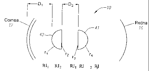
[0016] Fig. 1 diagrammatically illustrates a pair of optics for a multi-ocular
system
disposed with reference to the cornea and the retina.
[0017] Fig. 2 shows an example dual optic lens with haptics extending from one
optic.
100181 Fig. 3 is a plan view of the optic of Fig. 2 further illustrating T-
shaped haptics.
[0019] Fig. 4 is a cross-sectional view showing the optics as well as plural
spacers
attaching the two optics together.
[00201 Fig. 5 is a further view of a posterior lens.
[0021] Fig. 6 is a further view of an anterior lens having a larger diameter
than the
postenor lens.
[0022] Figures 7a-7b are side and plan views illustrating optics and suitable
spacers.
[00231 Figs. 8 through 12 are diagraimiiatic views illustrating different
placements of
lenses in the eye with Fig. 8 showing a conventional placement in the capsular
bag, Fig. 9
showing two lenses in the capsular bag, Fig. 10 showing one lens in the
capsular bag and one
in the sulcus, Fig. 11 showing one lens in the bag and one in the anterior
chamber, and Fig. 12
showing two optics integrally linked in the bag.
[0024] Fig. 13 shows the lens system in vitro.
10025] Fig. 14 shows the lens system in vitro optic fibrosis.
[0026] Fig. 15 illustrates a human eye with a currently available
accommodating
intraocular lens.
[0027] Turning now to these drawings, and first to Figure 15, there is
illustrated a human
eye 10 whose natural crystalline lens matrix has been removed from the natural
lens capsule of
the eye through an anterior opening in the capsule formed by an anterior
capsulotomy, in this
case a continuous tear circular capsulotomy, or capsulorhexis. As noted
earlier, this natural
lens matrix, which is normally optically clear, often becomes cloudy and forms
a cataract
which is cured by removing the matrix and replacing it with an artificial
intraocular lens.
[0028] Continuous tear circular capsulotomy, or capsulorhexis, involves
tearing the
anterior capsule along a generally circular tear line in such a way as to form
a relatively
smooth-edged circular opening in the center of the anterior capsule. The
cataract is removed
from the natural lens capsule through this opening. After completion of this
surgical
procedure, the eye includes an optically clear anterior cornea 12, an opaque
sclera 14 on the
inner side of which is the retina 16 of the eye, an iris 18, a capsular bag 20
behind the iris, and
a vitreous cavity 21 behind the capsular bag filled with the gel-like vitreous
humor. The
CA 02658248 2009-01-15
WO 2008/022211 PCT/US2007/076026
capsular bag 20 is the structure of the natural lens of the eye which remains
intact within the
eye after the continuous tear circular tear capsulorhexis has been performed
and the natural
lens matrix has been removed from the natural lens.
[00291 The capsular bag 20 includes an annular anterior capsular remnant or
rim 22 and an
elastic posterior capsule 24 which are joined along the perimeter of the bag
to form an annular
crevice-like cul-de-sac 25 between rim and posterior capsule. The capsular rim
22 is the
remnant of the anterior capsule of the natural lens which remains after
capsulorhexis has been
performed on the natural lens. This rim circumferentially surrounds a central,
generally round
anterior opening 26 (capsulotomy) in the capsular bag through which the
natural lens matrix
was previously removed from the natural lens. The capsular hag 20 is secured
about its
perimeter to the ciliary muscle 28 of the eye by zonules 30.
[00301 Natural accommodation in a normal human eye having a normal human
crystalline
lens involves automatic contraction or constriction and relaxation of the
ciliary muscle of the
eye by the brain in response to looking at objects at different distances.
Ciliary muscle
relaxation, which is the noisnal state of the muscle, shapes the human
crystalline lens for
distant vision. Ciliary muscle contraction shapes the human crystalline lens
for near vision.
The brain-induced change from distant vision to near vision is referred to as
accommodation.
[00311 Implanted within the capsular bag 20 of the eye 10 is an accommodating
intraocular
lens 32 such as shown in U.S. Patent No. 7,048,760 which replaces and performs
the
accommodation function of the removed human crystalline lens. The
accommodating
intraocular lens may be utilized to replace either a natural lens which is
virtually totally
defective, such as a cataractous natural lens, or a natural lens that provides
satisfactory vision
at one distance without the wearing of glasses but provides satisfactory
vision at another
distance only when glasses are worn. For example, the accommodating
intraocular lens of the
invention as described below can be utilized to correct refractive errors and
restore
accommodation for persons in their mid-40s who require reading glasses or
bifocals for near
vision.
[00321 Intraocular lens 32 comprises a unitary body which may be formed of
relatively
hard material, relatively soft flexible semi-rigid material, or a combination
of both hard and
soft materials. Examples of relatively hard materials which are suitable for
the lens body are
methyl methacrylate, polysulfones, and other relatively hard biologically
inert optical
materials. Examples of suitable relatively soft materials for the lens body
are silicone,
hydrogels, thermolabile materials, and other flexible semi-rigid biologically
inert optical
materials.
6
CA 02658248 2009-01-15
WO 2008/022211 PCT/US2007/076026
DESCRIPTION OF THE PREFERRED EMBODIMENTS
[00331 The lens system comprises two optics fused together, one in front of
the other, as
will be further explained beginning with Fig. I below. T-shaped extended
portions or plate
haptics 36 extend from diametrically opposite edges of the optic. These
haptics include haptic
members or plates 36 proper having inner ends joined one or other of the
optics and opposite
outer free ends and lateral fixation fingers at their outer ends. The haptic
plates 36 may be
longitudinally tapered so as to narrow or widen in width toward their ends or
may be wider in
their periphery and narrower adjacent to the optic. The optical system 34 is
movable anteriorly
and posteriorly relative to the haptics 36. The preferred lens embodiment
illustrated is
constructed of a resilient semi-rigid material and has flexible hinges 38
which join the inner
ends of the haptic plates 36 to one of the optics. The haptics are relatively
rigid and are
flexible about the hinges anteriorly and posteriorly relative to the optic.
These hinges are
formed by grooves 38 which enter either the anterior or posterior sides and
extend across the
inner ends of the haptic plates 36. The haptics 36 are flexible about the
hinges 38 in the
anterior and posterior directions of the optical system. The lens has a
relatively flat unstressed
configuration, wherein the haptics 36 and their hinges 38 are disposed in a
common plane
transverse to the optic axis of the optic 34. Defonnation of the lens from
this normal
unstressed configuration by anterior or posterior movement of the haptics
about their hinges
creates in the hinges elastic strain energy forces which urge the lens to its
normal unstressed
configuration. The outer end edges of the haptics are preferably circularly
curved to equal radii
about the optic axis of the optic 34. Anterior movement of the optical system
toward the iris
also is aided by an increase in vitreous cavity pressure upon constriction of
the ciliary muscle.
Furthermore this increase in pressure can also deform one or both of the optic
further aiding
near vision.
[00341 Turning now to Fig. 1, the same diagrainmatically illustrates the human
eye 10, the
cornea 12, the retina 16, and further including an anterior optic 40 and
posterior optic 41.
Although not shown in Fig. 1, normally the posterior optic 41 includes haptics
36 such as seen
in Figs. 2 and 3 (and Fig. 13). Dl represents the distance from the cornea 12
to the first optic
40 and D2 the space between the two optics 40 and 41. D2 typically ranges from
0 to 3.0 mm,
one of the optics can have a torric surface.
100351 The letters "r" represent the four possible radii of the two optics,
and they range
from 4.9 mm to 6.0 mm. RI, represents ihe refractive index of the aqueous
between the cornea
12 and first optic 40, RI, and RIz represent the refractive indices of
respective optics 40 and
41, RIl' represents the aqueous between the two optics, and R3 represents the
refractive index
of the vitreous between posterior lens 41 and the retina 16. RI1 is typically
1.336, RI3 1.336,
7
CA 02658248 2009-01-15
WO 2008/022211 PCT/US2007/076026
and RIz 1.427, D? is 1.0 to 2.0 mm and typically 1.4 mm. The various radii,
refractive indices
and distances between the optics can be adjusted to give the greatest depth of
focus.
[00361 Fig. 2 illustrates the multi-ocular lens systenl wherein the anterior
optic 40 has a
larger diameter than the posterior optic 41. The lens has haptics 36 with
hinges 38 adjacent the
optic 41. Fig. 3 is a plan view of the posterior optic 41 illustrating T-
shaped haptics 36, hinges
38 adjacent the optic, and fixation fingers 44. Fig. 4 illustrates the manner
in which the two
optics 40 and 41 are spaced and can be sealed with posts 46, preferably with
liquid silicone and
heat. The design is such that the anterior optic 40 can attach to the
posterior lens 41. As can
be seen from Figs. 9 - 1l, the anterior optic 40 can have haptics and fixation
fingers like lens
41.
[00371 Figs. 5 through 7b illustrate the posterior lens 41, anterior optic 40,
and stakes 48,
via which the anterior optic can be connected with suitable holes 50 or 50' as
seen in Figs. 5
and 7b. The two optics 40 and 41 can be attached before implailtation or after
implantation.
The anterior optic 40 can be detachable so that it can be changed after
implantation to provide
a power change or a torricity charge.
[0038] The lens 41 can have an optic diameter of 4.0 - 6.5 mm, length from
haptic 36 end
to end of 10.0 - 12.5 mm, loop 44 tip to loop tip 10.5 - 13.0 mm, hinge 38
width 1.0 - 5.0 mm
and depth at base of 0.05 - 1.0 mm. Typical materials are silicone, acrylic or
any suitable
optical material, and polymide or other logs material such as PMAA.
[0039] Turning now to Figs. 8 through 12, Fig. 8 is a schematic representation
similar to
Fig. 13 showing an optic 34 of a standard intraocular lens in the capsular bag
20. Fig. 9
diagrammatically illustrates both lenses 40 and 41 with haptics disposed in
the capsular bag.
Fig. 10 diagrammatically illustrates optic 41 in the capsular bag 20 and the
anterior optic 40 in
the sulcus.
[0040] Fig. 11 diagrammatically illustrates two individual lenses 41 in the
capsular bag 20,
and the lens 40 in the anterior chamber. Fig. 12 illustrates the lens system
40 and 41 integrally
linked and disposed in the capsular bag. In each case, the posterior optic can
be standard
accommodating intraocular lens.
100411 Either lens 40 or 41 can be a stabilized accommodating intraocular lens
according
to patent application Serial No. 11/461,290 filed July 31, 2006, Attorney
Docket No.
13533.4069.
[0042] Fig. 13 shows the lens systern in vitro. The lens system may be
designed such that
the haptics are attached to the anterior optic resulting in an anterior vault
when the lens system
8
CA 02658248 2009-01-15
WO 2008/022211 PCT/US2007/076026
is focused for distance as in Fig. 14 or to the posterior optic resulting in a
posterior vault when
the lens system is in the distance position. Fig. 14 shows the lens in vitro
after fibrosis
[0043] While an embodiment of the present invention has been shown and
described,
various modifications may be made without departing from the scope of the
present invention,
and all such modifications and equivalents are intended to be covered.
9