Note: Descriptions are shown in the official language in which they were submitted.
CA 02658250 2009-01-15
WO 2008/014084 PCT/US2007/072519
PIPELINE
Cross Reference To Re[ated Applications
This appiication claims the benefit of the filing date of U.S. utility patent
application serial
number 11/560,154, attorney docket number 25791.407.02, filed on 15 Nov 2006
which claims benefit
of the filing date of U.S. provisional patent application serial number
60/832,909, attorney docket
nurnber 25791,407, filed on 24 Jul 2006, the disclosures of which are
incorporated herein by
reference.
This application is a continuation-in-part of U.S. application serial no.
11/084,788, attorney
docket no. 25791.325, filed on 18 Mar 2005, which was a continuation-in-part
of U.S. application
serial no. 10/418,687, attorney docket no. 25791.228, filed on 18 Apr 2003
which issued as U.S.
Patent No. 7,021,390, which was a continuation of U.S. application serial no.
09/852,026, attorney
docket no. 25791.56, filed on 9 May 2001, which issued as U.S. Patent No.
6,561,227, which was a
divisional of U.S. application serial no. 09/454,139, attorney docket no.
25791.3.02, filed on 03 Dec
1999, which issued as U.S. Patent No. 6,497,289, which claimed the benefit of
the filing date of U.S.
Provisional Patent Application Serial Number 60{111,293, attorney docket
number 25791.3, filed on
07 Dec 1998, the disclosures of which are incorporated herein by reference.
This application is related to the following co-pending applications: (1) U.S.
Patent Number
6,497,289, which was filed as U.S. Patent Application serial no. 09/454,139,
attorney docket no.
25791.03.02, fiied on 03 Dec 1999, which claims priority from provisional
application 60/111,293, filed
on 07 Dec 1998, (2) U.S. patent application serial no. 09/510,913, attorney
docket no. 25791.7.02,
filed on 23 Feb 2000, which claims priority from provisional application
60/121,702, filed on 25 Feb
1999, (3) U.S. patent application serial no. 09/502,350, attorney docket no.
25791.8.02, filed on 10
Feb 2000, which claims priority from provisional application 60/119,611, filed
on 11 Feb 1999, (4) U.S.
patent no. 6,328,113, which was filed as U.S. Patent Application serial number
09/440,338, attorney
docket number 25791.9.02, filed on 15 Nov 1999, which claims priority from
provisional application
60/108,558, filed on 16 Nov 1998, (5) U.S. patent application serial no.
10/169,434, attorney docket
no. 25791.10.04, filed on 01 Jul 2002, which claims priority from provisional
application 60/183,546,
filed on 18 Feb 2000 6) U.S. patent no. 6,640,903 which was filed as U.S.
patent application serial no.
09/523,468, attorney docket no. 25791.11.02, filed on 10 Mar 2000, which
claims priority from
provisional application 60/124,042, filed on 11 Mar 1999, (7) U.S. patent
number 6,568,471, which
was filed as patent application serial no. 09/512,895, attorney docket no.
25791.12_02, filed on 24 Feb
2000, which claims priority from provisional application 60/121,841, filed on
26 Feb 1999, (8) U.S.
patent number 6,575,240, which was filed as patent application serial no.
09/511,941, attorney docket
no. 25791.16.02, filed on 24 Feb 2000, which claims priority from provisional
application 60/121,907,
filed on 26 FEB 1999, (9) U.S. patent number 6,557,640, which was filed as
patent application serial
no. 09/588,946, attorney docket no. 25791.17.02, filed on 07 Jun 2000, which
claims priority from
provisional application 60/137,998, filed on 07 Jun 1999, (10) U.S. patent
application seriai na.
091981,916, attorney docket no. 25791.18, filed on 18 Oct 2001 as a
continuation-in-part application
of U.S. patent no. 6,328,113, which was filed as U.S. Patent Application
serial number 09/440,338,
attorney docket number 25791.9.02, filed on 15 Nov 1999, which claims priority
from provisional
application 60/108,558, filed on 16 Nov 1998, (11) U.S. patent number
6,604,763, which was filed as
1
SUBSTITUTE SHEET (RULE 26)
CA 02658250 2009-01-15
WO 2008/014084 PCT/US2007/072519
application serial no. 09/559,122, attorney docket no. 25791.23.02, filed on
26 Apr 2000, which claims
priority from provisional application 60/131,106, filed on 26 Apr 1999, (12)
U.S. patent application
serial no. 10/030,593, attorney docket no. 25791.25.08, filed on 08 Jan 2002,
which claims priority
from provisional application 60/146,203, filed on 29 Jul 1999, (13) U.S.
provisional patent application
serial no. 60/143,039, attorney docket no. 25791.26, filed on 09 Jul 1999,
(14) U.S. patent application
seriai no. 10/111,982, attorney docket no. 25791.27.08, filed on 30 Apr 2002,
which claims priority
from provisionaf patent application serial no. 60/162,671, attorney docket no.
25791.27, filed on 07
Nov 1999, (15) U.S. provisional patent application serial no. 60/154,047,
attorney docket no.
25791.29, filed on 16 Sep 1999, (16) U.S. provisional patent application
serial no. 60/438,828,
attorney docket no. 25791.31, filed on 09 Jan 2003, (17) U.S. patent number
6,564,875, which was
filed as application serial no. 09/679,907, attorney docket no. 25791.34.02,
on 05 Oct 2000, which
claims priority from provisional patent application serial no. 60/159,082,
attorney docket no. 25791.34,
filed on 12 Oct 1999, (18) U.S. patent appiication serial no. 10/089,419,
filed on 27 Mar 2002, attorney
docket no. 25791.36.03, which claims priority from provisional patent
application serial no.
60/159,039, attorney docket no. 25791.36, filed on 12 Oct 1999, (19) U.S.
patent application serial no.
09/679,906, filed on 05 Oct 2000, attorney docket no. 25791.37.02, which
claims priority from
provisional patent application serial no. 60/159,033, attorney docket no.
25791.37, filed on 12 Oct
1999, (20) U.S. patent application serial no. 10/303,992, fiied on 22 Nov
2002, attorney docket no.
25791.38.07, which claims priority from provisional patent application serial
no. 60/212,359, attorney
docket no. 25791.38, filed on 19 Jun 2000, (21) U.S. provisional patent
application serial no.
60/165,228, attorney docket no. 25791.39, filed on 12 Nov 1999, (22) U.S.
provisional patent
application serial no. 60/455,051, attorney docket no. 25791.40, filed on 14
Mar 2003, (23) PCT
application US02/2477, filed on 26 Jun 2002, attorney docket no. 25791.44.02,
which claims priority
from U.S. provisional patent application serial no. 60/303,711, attorney
docket no. 25791.44, filed on
06 Jul 2001, (24) U.S. patent application serial no. 10/311,412, filed on 12
Dec 2002, attorney docket
no. 25791.45.07, which claims priority from provisional patent application
serial no. 60/221,443,
attorney docket no. 25791.45, filed on 28 Jul 2000, (25) U.S. patent number
7,100,684 which was
filed as application serial no. 10/322,947, on 18 ec 2002, attorney docket
no. 25791.46.07, which
claims priority from provisional patent application serial no. 60/221,645,
attorney docket no. 25791.46,
filed on 28 Jul 2000, (26) U.S. patent application serial no. 10/322,947,
filed on 22 Jan 2003, attorney
docket no. 25791 .47.03, which claims priority from provisional patent
application serial no.
60/233,638, attorney docket no. 25791.47, filed on 18 Sep 2000, (27) U.S.
patent application serial
no. 10/406,648, filed on 31 Mar 2003, attorney docket no. 25791.48.06, which
claims priority from
provisional patent application serial no. 60/237,334, attorney docket no.
25791 .48, filed on 02 Oct
2000, (28) PCT application 1tS02/04353, filed on 14 Feb 2002, attorney docket
no. 25791.50.02,
which claims priority from U.S. provisional patent application serial no.
60/270,007, attorney docket
no. 25791.50, filed on 20 Feb 2001, (29) U.S. patent application serial no.
10/465,835, filed on 13 Jun
2003, attorney docket no. 25791.51.06, which claims priority from provisional
patent application serial
no. 60/262,434, attorney docket no. 25791.51, filed on 17 Jan 2001, (30) U.S.
patent application serial
no. 10/465,831, filed on 13 Jun 2003, attorney docket no. 25791.52.06, which
claims priority from
U.S. provisional patent application serial no. 60/259,486, attorney docket no.
25791.52, filed on 03
2
SUBSTITUTE SHEET (RULE 26)
CA 02658250 2009-01-15
WO 2008/014084 PCT/US2007/072519
Jan 2001, (31) U.S. provisional patent application serial no. 60/452,303,
filed on 05 Mar 2003,
attorney docket no. 25791.53, (32) U.S. patent number 6,470,966, which was
filed as patent
application serial number 09/850,093, filed on 07 May 2001, attorney docket
no. 25791.55, as a
divisional application of U.S. Patent Number 6,497,289, which was filed as
U.S. Patent Application
serial no. 09/454,139, attorney docket no. 25791.03.02, filed on 03 Dec 1999,
which claims priority
from provisional application 60/111,293, filed on 07 Dec 1998, (33) U.S.
patent number 6,561,227,
which was filed as patent application serial number 09/852,026 , filed on 09
May 2001, attorney
docket no. 25791.56, as a divisional application of U.S. Patent Number
6,497,289, which was filed as
U.S. Patent Application serial no. 09/454,139, attorney docket no.
25791.03.02, filed on 03 Dec 1999,
which claims priority from provisional application 60/111,293, filed on 07 Dec
1998, (34) U.S. patent
application serial number 09/852,027, filed on 09 May 2001, attorney docket
no. 25791.57, as a
divisional appiication of U.S. Patent Number 6,497,289, which was filed as
U.S. Patent Application
serial no. 09/454,139, attorney docket no. 25791.03.02, filed on 03 Dec 1999,
which claims priority
from provisional application 60/111,293, filed on 07 Dec 1998, (35) PCT
Application US02/25608,
attorney docket no. 25791.58.02, filed on 13 Aug 2002, which claims priority
from provisional
application 60/318,021, filed on 07 Sep 2001, attorney docket no. 25791.58,
(36) PCT Application
US02/24399, attorney docket no. 25791.59.02, filed on 01 Aug 2002, which
claims priority from U.S.
provisional patent application serial no. 60/313,453, attorney docket no.
25791.59, filed on 20 Aug
2001, (37) PCT Application US02/29856, attorney docket no. 25791.60.02, filed
on 19 Sep 2002,
which clairns priority from U.S. provisional patent application serial no.
60/326,886, attorney docket
no. 25791.60, filed on 03 Oct 2001, (38) PCT Application US02120256, attorney
docket no.
25791.61.02, filed on 26 Jun 2002, which claims priority from U.S. provisional
patent application serial
no. 60/3E13,740, attorney docket no. 25791.61, filed on 06 Jul 2001, (39) U.S.
patent application serial
no. 09/962,469, filed on 25 Sep 2001, attorney docket no. 25791.62, which is a
divisional of U.S.
patent application serial no. 09/523,468, attorney docket no. 25791.11.02,
filed on 10 Mar 2000, (now
U.S. Patent 6,640,903 which issued 11/4/2003), which claims priority from
provisional application
60/124,042, filed on 11 MAR 1999, (40) U.S. patent application serial no.
09/962,470, filed on 25 Sep
2001, attorney docket no. 25791.63, which is a divisionai of U.S. patent
application serial no.
09/523,468, attorney docket no. 25791.11.02, filed on 10 Mar 2000, (now U.S.
Patent 6,640,903
which issued 11/4I2003), which claims priority from provisional application
60/124,042, filed on 11 Mar
1999, (41) U.S. patent application serial no. 09/962,471, filed on 25 Sep
2001, attorney docket no.
25791.64, which is a divisional of U.S. patent application serial no.
09/523,468, attorney docket no.
25791.11.02, filed onlO Mar 2000, (now U.S. Patent 6,640,903 which issued
11/4/2003), which claims
priority from provisional application 60/124,042, filed on 11 Mar 1999, (42)
U.S. patent application
serial no. 09/962,467, filed on 25 Sep 2001, attorney docket no. 25791.65,
which is a divisional of
U.S. patent application serial no. 09/523,468, attorney docket no.
25791.11.02, filed on 10 Mar 2000,
(now U.S. Patent 6,640,903 which issued 11/4/2003), which claims priority from
provisional
application 60/124,042, filed on 11 Mar 1999, (43) U.S. patent application
serial no. 09/962,468, filed
on 25 Sep 2001, attorney docket no. 25791.66, which is a divisional of U.S.
patent application serial
no. 09/523,468, attorney docket no. 25791.11.02, filed on 10 Mar 2000, (now
U.S. Patent 6,640,903
which issued 11/4/2003), which clairras priority from provisional application
60/124,042, filed on 11 Mar
3
SUBSTITUTE SHEET (RULE 26)
CA 02658250 2009-01-15
WO 2008/014084 PCT/US2007/072519
1999, (44) PCT application US 02/25727, filed on 14 Aug 2002, attorney docket
no. 25791.67.03,
which clairns priority from U.S. provisional patent application serial no.
60/317,985, attorney docket
no. 25791.67, filed on 06 Sep 2001, and U.S. provisional patent application
serial no. 60/318,386,
attorney docket no. 25791.67.02, filed on 10 Sep 2001, (45) PCT application US
02/39425, filed on 10
Dec 2002, attorney docket no. 25791 .68.02, which claims priority from U.S.
provisional patent
application serial no. 60/343,674 , attorney docket no. 25791.68, filed on 27
Dec 2001, (46) U.S.
utility patent application serial no. 09/969,922, attorney docket no.
25791.69, filed on 03 Oct 2001,
(now U.S. Patent 6,634,431 which issued 21 Oct 2003), which is a continuation-
in-part application of
U.S. patent no. 6,328,113, which was filed as U.S. Patent Application serial
nurnber 09/440,338,
attorney docket number 25791.9.02, filed on 15 Nov 1999, which claims priority
frorn provisional
application 60/108,558, filed on 16 Nov 1998, (47) U.S. utility patent
application serial no. 10/516,467,
attorney docket no. 25791.70, filed on 10 Dec 2001, which is a continuation
application of U.S. utility
patent application serial no. 09/969,922, attorney docket no. 25791.69, filed
on 03 Oct 2001, (now
U.S. Patent 6,634,431 which issued 21 Oct 2003), which is a continuation-in-
part application of U.S.
patent no. 6,328,113, which was filed as U.S. Patent Application serial number
091440,338, attorney
docket number 25791.9.02, filed on 15 Nov 1999, which claims priority from
provisional application
60/108,558, filed on 16 Nov 1998, (48) PCT application US 03/00609, filed on
09 Jan 2003, attorney
docket no. 25791.71.02, which claims priority from U.S. provisional patent
application serial no.
60/357,372 , attorney docket no. 25791.71, filed on 15 Feb 2002, (49) U.S.
patent application serial
no. 10/074,703, attorney docket no. 25791.74, filed on 12 Feb 2002, which is a
divisional of U.S.
patent number 6,568,471, which was filed as patent application serial no.
09/512,895, attorney docket
no. 25791.12.02, filed on 24 Feb 2000, which claims priority from provisional
application 60/121,841,
filed on 26 Feb 1999, (50) U.S. patent application serial no. 10/074,244,
attorney docket no.
25791.75, filed on 12 Feb 2002, which is a divisional of U.S. patent number
6,568,471, which was
filed as patent application serial no. 09/512,895, attorney docket no.
25791.12.02, filed on 24 Feb
2000, which claims priority from provisional application 60/121,841, filed on
26 Feb 1999, (51) U.S.
patent application serial no. 10/076,660, attorney docket no. 25791.76, filed
on 15 Feb 2002, which is
a divisional of U.S. patent number 6,568,471, which was filed as patent
application serial no.
09/512,895, attorney docket no. 25791.12.02, filed on 24 Feb 2000, which
claims priority from
provisional application 60/121,841, filed on 26 Feb 1999, (52) U.S. patent
application serial no.
10/076,661, attorney docket no. 25791.77, filed on 15 Feb 2002, which is a
divisional of U.S. patent
number 6,568,471, which was filed as patent application serial na. 09/512,895,
attorney docket no.
25791.12,02, filed on 24 Feb 2000, which claims priority from provisional
application 60/121,841, filed
on 26 Feb 1999, (53) U.S. patent application serial no. 10/076,659, attorney
docket no. 25791.78,
filed on 15 Feb 2002, which is a divisional of U.S. patent number 6,568,471,
which was filed as patent
application serial no. 09/512,895, attorney docket no. 25791.12.02, filed on
24 Feb 2000, which
claims priority from provisional application 60/121,841, filed on 26 Feb 1999,
(54) U.S. patent
application serial no. 10/078,928, attorney docket no. 25791.79, filed on 20
Feb 2002, which is a
divisional of U.S. patent number 6,568,471, which was filed as patent
application serial no.
09/512,895, attorney docket no. 25791.12.02, filed on 24 Feb 2000, which
claims priority from
provisional application 60/121,841, filed on 26 Feb 1999, (55) U.S. patent
application serial no.
4
SUBSTITUTE SHEET (RULE 26)
CA 02658250 2009-01-15
WO 2008/014084 PCT/US2007/072519
10/078,922, attorney docket no. 25791.80, filed on 20 Feb 2002, which is a
divisional of U.S. patent
number 6,568,471, which was filed as patent application serial no. 09/512,895,
attorney docket no.
25791.12.02, filed on 24 Feb 2000, which claims priority from provisional
application 60/121,841, filed
on 26 Feb 1999, (56) U.S. patent application serial no. 10/078,921, attorney
docket no. 25791.81,
filed on 20 Feb 2002, which is a divisional of U.S. patent number 6,568,471,
which was filed as patent
application serial no. 09/512,895, attorney docket no. 25791.12.02, filed on
24 Feb 2000, which
ciaims priority from provisional appiication 60/121,841, filed on 26 Feb 1999,
(57) U.S. patent
application serial no. 10/261,928, attorney docket no. 25791.82, filed on 01
Oct 2002, which is a
divisionai of U.S. patent number 6,557,640, which was filed as patent
application serial no.
09/588,946, attorney docket no. 25791.17.02, filed on 07 Jun 2000, which
claims priority from
provisional application 60/137,998, filed on 07 Jun 1999, (58) U.S. patent
application serial no.
10/079,276, attorney docket no. 25791.83, filed on 20 Feb 2002, which is a
divisional of U.S. patent
number 6,568,471, which was filed as patent application serial no. 09/512,895,
attorney docket no.
25791.12.02, filed on 24 Feb 2000, which clairrts priority from provisional
application 60/121,841, filed
on 26 Feb 1999, (59) U.S. patent application serial no. 10/262,009, attorney
docket no. 25791.84,
filed on 01 Oct 2002, which is a divisional of U.S. patent number 6,557,640,
which was filed as patent
application serial no. 09/588,946, attorney docket no. 25791.17.02, filed on
07 Jun 2000, which claims
priority from provisional application 60/137,998, filed on 07 Jun 1999, (60)
U.S. patent application
serial no. 10/092,481, attorney docket no. 25791.85, filed on 07 Mar 2002,
which is a divisional of
U.S. patent number 6,568,471, which was filed as patent application serial no.
09/512,895, attorney
docket no. 2579112_02, filed on 24 Feb 2000, which claims priority from
provisional application
60/121,841, fifed on 26 Feb 1999, (61) U.S. patent appiication serial no.
10/261,926, attorney docket
no. 25791.86, filed on 01 Oct 2002, which is a divisional of U.S. patent
number 6,557,640, which was
filed as patent application serial no. 09/588,946, attorney docket no.
25791.17.02, filed on 07 Jun
2000, which claims priority from provisional application 601137,998, filed on
07 Jun 1999, (62) PCT
application US 02/36157, filed on 12 i`1ov 2002, attorney docket no.
25791.87.02, which claims
priority from U.S. provisional patent application seriai no. 60/338,996,
attorney docket no. 25791.87,
filed on 12 Nov 2001, (63) PCT application US 02/36267, filed on 12 Nov 2002,
attorney docket no.
25791.88.02, which claims priority from U.S. provisional patent application
serial no. 60/339,013,
attorney docket no. 25791.88, filed on 12 Nov 2001, (64) PCT application US
03/11765, fifed on 16
Apr 2003, attorney docket no. 25791 .89.02, which clairns priority from U.S.
provisional patent
application serial no. 60/383,917, attorney docket no. 25791.89, filed on 29
May 2002, (65) PCT
application US 03/15020, filed on 12 May 2003, attorney docket no.
25791.90.02, which claims priority
from U.S. provisional patent application serial no. 60/391,703, attorney
docket no. 25791.90, filed on
26 Jun 2002, (66) PCT application US 02/39418, filed on 10 Dec 2002, attorney
docket no.
25791.92.02, which claims priority from U.S. provisional patent application
serial no. 60/346,309,
attorney docket no. 25791.92, filed on 07 Jan 2002, (67) PCT application US
03/06544, filed on 04
Mar 2003, attorney docket no. 25791.93.02, which claims priority from U.S.
provisional patent
application serial no. 60/372,048, attorney docket no. 25791.93, filed on 12
Apr 2002, (68) U.S. patent
application serial no. 10/331,718, attorney docket no. 25791.94, filed on 30
aec 2002, which is a
divisional U.S. patent application serial no. 09/679,906, filed on 05 Oct
2000, attorney docket no.
5
SUBSTITUTE SHEET (RULE 26)
CA 02658250 2009-01-15
WO 2008/014084 PCT/US2007/072519
25791.37.02, which claims priority from provisional patent appiication serial
no. 60/159,033, attorney
docket no. 25791.37, filed on 12 Oct 1999, (69) PCT application US 03/04837,
filed on 29 Feb 2003
2/29103, attorney docket no. 25791.95.02, which claims priority from U.S.
provisional patent
application serial no. 60/363,829, attorney docket no. 25791.95, filed on 13
Mar 2002, (70) U.S.
patent application serial no. 10/261,927, attorney docket no. 25791.97, filed
on 01 Oct 2002, which is
a divisional of U.S. patent nunnber 6,557,640, which was filed as patent
appiication serial no.
09/588,946, attorney docket no. 25791.17.02, filed on 07 Jun 2000, which
claims priority from
provisionai application 60/137,998, filed on 07 Jun 1999, (71) U.S. patent
application serial no.
10/262,008, attorney docket no. 25791.98, filed on 01 Oct 2002, which is a
divisional of U.S. patent
number 6,557,640, which was filed as patent application serial no. 09/588,946,
attorney docket no.
25791.17.02, filed on 07 Jun 2000, which claims priority from provisional
application 60/137,998, filed
on 07 Jun 1999, (72) U.S. patent application serial no. 10/261,925, attorney
docket no. 25791.99,
filed on 01 Oct 2002, which is a divisional of U.S. patent number 6,557,640,
which was filed as patent
application serial no. 09/588,946, attorney docket no. 25791.17.02, filed on
07 Jun 2000, which claims
priority from provisional application 60/137,998, filed on 07 Jun 1999, (73)
U.S. patent application
serial no. 10/199,524, attorney docket no. 25791.100, filed on 19 JUL 2002,
which is a continuation of
U.S. Patent Number 6,497,289, which was filed as U.S. Patent Application
serial no. 09/454,139,
attorney docket no. 25791.03.02, filed on 03 DEC 1999, which claims priority
from provisional
application 60/111,293, filed on 07 Dec 1998, (74) PCT application US
03/10144, filed on 28 Mar
2003, attorney docket no. 25791.101.02, which claims priority from U.S.
provisional patent application
serial no. 60/372,632, attorney docket no. 25791.101, filed on 15 Apr 2002,
(75) U.S. provisional
patent application serial no. 60/412,542, attorney docket no. 25791.102, filed
on 20 Sep 2002, (76)
PCT appiication US 03/14153, filed on 06 May 2003, attorney docket no.
25791.104.02, which claims
priority from U.S. provisional patent appiication serial no. 60/380,147,
attorney docket no. 25791.104,
filed on 06 May 2002, (77) PCT application US 03/19993, filed on 24 Jun 2003,
attorney docket no.
25791.106.02, which claims priority from U.S. provisional patent application
serial no. 60/397,284,
attorney docket no. 25791.106, filed on 19 Jul 2002, (78) PCT application US
03/13787, filed on 05
May 2003, attorney docket no. 25791.107.02, which claims priority from U.S.
provisional patent
application serial no. 60/387,486, attorney docket no. 25791.107, filed on 10
Jun 2002, (79) PCT
appiication US 03/18530, filed on 11 Jun 2003, attorney docket no.
25791.108.02, which claims
priority from U.S. provisional patent application serial no. 60/387,961,
attorney docket no. 25791.108,
filed on 12 Jun 2002, (80) PCT application US 03/20694, filed on 01 Jul 2003,
attorney docket no.
25791.110.02, which claims priority from U.S. provisional patent application
serial no. 60/398,061,
attorney docket no. 25791.110, filed on 24 Jul 2002, (81) PCT application US
03/20870, filed on 02
Jul 2003, attorney docket no. 25791.111.02, which claims priority from U.S.
provisional patent
application serial no. 60/399,240, attorney docket no. 25791.111, filed on 29
Jul 2002, (82) U.S.
provisional patent application serial no. 60/412,487, attorney docket no.
25791.112, filed on 20 Sep
2002, (83) U.S. provisional patent application serial no. 60/412,488, attorney
docket no. 25791.114,
filed on 20 Sep 2002, (84) U.S. patent application serial no. 10/280,356,
attorney docket no.
25791.115, filed on 25 Oct 2002, which is a continuation of U.S. patent number
6,470,966, which was
filed as patent application serial number 09/850,093, filed on 07 May 2001,
attorney docket no.
6
SUBSTITUTE SHEET (RULE 26)
CA 02658250 2009-01-15
WO 2008/014084 PCT/US2007/072519
25791.55, as a divisional application of U.S. Patent Number 6,497,289, which
was filed as U.S. Patent
Application serial no. 09/454,139, attorney docket no. 25791.03.02, filed on
03 DEC 1999, which
claims priority from provisional application 60/111,293, filed on 07 Dec 1998,
(85) U.S. provisional
patent application serial no. 60/412,177, attorney docket no. 25791.117, filed
on 20 Sep 2002, (86)
U.S. provisional patent application serial no. 60/412,653, attorney docket no.
25791.118, filed on 20
Sep 2002, (87) U.S. provisional patent application serial no. 601405,610,
attorney docket no.
25791.119, filed on 23 Aug 2002, (88) U.S. provisional patent application
serial no. 601405,394,
attorney docket no. 25791.120, filed on 23 Aug 2002, (89) U.S. provisional
patent application serial
no. 60/412,544, attorney docket no. 25791.121, filed on 20 Sep 2002, (90) PCT
application US
03/24779, filed on 08 Aug 2003, attorney docket no. 25791.125.02, which claims
priority from U.S.
provisional patent application serial no. 60/407,442, attorney docket no.
25791.125, filed on 30 Aug
2002, (91) U.S. provisional patent application serial no. 60/423,363, attorney
docket no. 25791.126,
filed on 10 Dec 2002, (92) U.S. provisional patent application serial no.
60/412,196, attorney docket
no. 25791.127, filed on 20 Sep 2002, (93) U.S. provisional patent application
serial no. 60/412,187,
attorney docket no. 25791.128, filed on 20 Sep 2002, (94) U.S. provisional
patent application serial
no. 60/412,371, attorney docket no. 25791.129, filed on 20 Sep 2002, (95) U.S.
patent application
serial no. 10/382,325, attorney docket no. 25791.145, filed on 05 Mar 2003,
which is a continuation of
U.S. patent number 6,557,640, which was filed as patent application serial no.
09/588,946, attorney
docket no. 25791.17.02, fiied on 07 Jun 2000, which ciaims priority from
provisional application
60/137,998, filed on 07 Jun 1999, (96) U.S. patent application serial no.
10/624,842, attorney docket
no. 25791.151, filed on 22 Jul 2003, which is a divisional of U.S. patent
application serial no.
09/502,350, attorney docket no. 25791.8.02, filed on 10 Feb 2000, which claims
priority from
provisional application 60/119,611, filed on 11 Feb 1999, (97) U.S.
provisional patent application
serial no. 60/431,184, attorney docket no. 25791.157, fiied on 05 Dec 2002,
(98) U.S. provisional
patent application serial no. 60/448,526, attorney docket no_ 25791.185, filed
on 18 Feb 2003, (99)
U.S. provisional patent application seriai no. 60/461,539, attorney docket no.
25791.186, filed on 09
Apr 2003, (100) U.S. provisional patent application serial no. 60/462,750,
attorney docket no.
25791,193, filed on 14 Apr 2003, (101) U.S. provisional patent application
serial no. 60/436,106,
attorney docket no. 25791.200, filed on 23 Dec 2002, (102) U.S. provisional
patent application serial
no. 60/442,942, attorney docket no. 25791.213, filed on 27 Jan 2003, (103)
U.S. provisional patent
application serial no. 60/442,938, attorney docket no. 25791.225, filed on 27
Jan 2003, (104) U.S.
provisional patent application serial no. 60/418,687, attorney docket no.
25791228, filed on 18 Apr
2003, (105) U.S. provisional patent application serial no. 60/454,896,
attorney docket no. 25791.236,
filed on 14 Mar 2003, (106) U.S. provisional patent application serial no.
60/450,504, attorney docket
no. 25791.238, filed on 26 Feb 2003, (107) U.S. provisional patent application
serial no. 60/451,152,
attorney docket no. 25791.239, filed on 09 Mar 2003, (108) U.S. provisional
patent application serial
no. 60/455,124, attorney docket no. 25791.241, filed on 17 Mar 2003, (109)
U.S. provisional patent
application serial no. 60/453,678, attorney docket no. 25791253, filed on 11
Mar 2003, (110) U.S.
patent application serial no. 10/421,682, attorney docket no. 25791.256, filed
on 23 Apr 2003, which
is a continuation of U.S. patent application serial no. 09/523,468, attorney
docket no. 25791.11.02,
filed on 10 Mar 2000, (now U.S. Patent 6,640,903 which issued 11/4/2003),
which claims priority from
7
SUBSTITUTE SHEET (RULE 26)
CA 02658250 2009-01-15
WO 2008/014084 PCT/US2007/072519
provisional application 60/124,042, filed on 11 Mar 1999, (111) U.S.
provisional patent application
serial no. 60/457,965, attorney docket no. 25791.260, filed on 27 Mar 2003,
(112) U.S. provisional
patent application serial no. 601455,718, attorney docket no. 25791.262, filed
on 18 Mar 2003, (113)
U.S, patent number 6,550,821, which was filed as patent application serial no.
09/811,734, filed on 19
Mar 2001, (114) U.S. patent application serial no. 10/436,467, attorney docket
no. 25791.268, filed
on 12 May 2003, which is a continuation of U.S. patent number 6,604,763, which
was filed as
application serial no. 09/559,122, attorney docket no. 25791.23.02, filed on
26 Apr 2000, which clairns
priority from provisional application 60/131,106, filed on 26 Apr 1999, (115)
U.S. provisional patent
application serial no. 60/459,776, attorney docket no. 25791.270, filed on 02
Apr 2003, (116) U.S.
provisional patent application serial no. 60/461,094, attorney docket no.
25791 .272, filed on 08 Apr
2003, (117) U.S. provisional patent application serial no. 60/461,038,
attorney docket no. 25791 .273,
filed on 07 Apr 2003, (118) U.S. provisional patent application serial no.
60/463,586, attorney docket
no. 25791.277, filed on 17 Apr 2003, (119) U.S. provisional patent application
serial no. 60/472,240,
attorney docket no. 25791.286, filed on 20 May 2003, (120) U.S. patent
application serial no.
10/619,285, attorney docket no. 25791.292, filed on 14 Jul 2003, which is a
continuation-in-part of
U.S. utility patent application serial no. 09/969,922, attorney docket no.
25791.69, filed on 03 Oct
2001, (now U.S. Patent 6,634,431 which issued 10/21/2003), which is a
continuation-in-part
application of U.S. patent no. 6,328,113, which was filed as U.S. Patent
Application serial number
09/440,338, attorney docket number 25791.9.02, filed on 15 Nov 1999, which
claims priority from
provisional application 60/108,558, filed on 16 Nov 1998, (121) U.S. utility
patent application serial no.
10/418,688, attorney docket no. 25791257, which was filed on 18 Apr 2003, as a
division of U.S.
utility patent application serial no. 09/523,468, attorney docket no.
25791.11.02, filed on 10 Mar 2000,
(now U.S. Patent 6,640,903 which issued 11/4/2003), which claims priority from
provisional
application 60/124,042, filed on 11 Mar 1999; (122) PCT patent application
serial no.
PCT/US2004I06246, attorney docket no. 25791.238.02, filed on 26 Feb 2004;
(123) PCT patent
application serial number PCT/US2004/08170, attorney docket number
25791.40.02, filed on 15 Mar
2004; (124) PCT patent application serial number PCT/US2004/08171, attorney
docket number
25791.236.02, filed on 15 Mar 2004; (125) PCT patent application serial number
PCT/US2004/08073,
attorney docket number 25791.262.02, filed on 18 Mar 2004; (126) PCT patent
application serial
number PCT/US2004/07711, attorney docket number 25791.253.02, filed on 11 Mar
2004; (127) PCT
patent application seriai number PCT/US2004/029025, attorney docket number
25791.260.02, filed
on 26 Mar 2004; (128) PCT patent application serial number PCT/US2004/01 03 1
7, attorney docket
number 25791.270.02, filed on 02 Apr 2004; (129) PCT patent application serial
number
PCT/US2004/010712, attorney docket number 25791.272.02, filed on 06 Apr 2004;
(130) PCT patent
application seriai number PCT/US20041010762, attorney docket number 25791
.273.02, filed on 06
Apr 2004; (131) PCT patent application serial number PCT/US2004/011973,
attorney docket number
25791.277.02, filed on 15 Apr 2004; (132) U.S. provisional patent application
serial number
60/495056, attorney docket number 25791.301, filed on 14 Aug 2003; (133) U.S.
provisional patent
application serial number 60/600679, attorney docket number 25791.194, filed
on 11 Aug 2004; (134)
PCT patent application serial number PCT/US2005/027318, attorney docket number
25791.329.02,
filed on 29 Jul 2005; (135) PCT patent application serial number
PCT/US2005/028936, attorney
8
SUBSTITUTE SHEET (RULE 26)
CA 02658250 2009-01-15
WO 2008/014084 PCT/US2007/072519
docket number 25791338.02, filed on 12 Aug 2005; (136) PCT patent application
serial number
PCT/US2005/028669, attorney docket number 25791.194.02, filed on 11 Aug 2005;
(137) PCT patent
application serial number PCT/US2005/028453, attorney docket number 25791.371,
filed on 11 Aug
2005; (138) PCT patent application serial number PCT/US2005/028641, attorney
docket number
25791.372, filed on 11 Aug 2005; (139) PCT patent application serial number
PCT/US2005/028819,
attorney docket number 25791.373, filed on 11 Aug 2005; (140) PCT patent
application serial number
PCT/US2005/028446, attorney docket number 25791.374, filed on 11 Aug 2005;
(141) PCT patent
application serial number PCT/US2045f028642, attorney docket number 25791.375,
filed on 11 Aug
2005; (142) PCT patent application serial number PCT/US2005/028451, attorney
docket number
25791.376, filed on 11 Aug 2005, and (143). PCT patent application serial
number
PCT/US20051028473, attorney docket number 25791.377, filed on 11 Aug 2005,
(144) U.S. utility
patent application serial number 10/546082, attorney docket number 25791.378,
filed on 16 Aug
2005, (145) U.S. utility patent application serial number 10/546076, attorney
docket number
25791.379, filed on 16 Aug 2005, (146) U.S. utility patent application serial
number 10/545936,
attorney docket number 25791.380, filed on 16 Aug 2005, (147) U.S. utility
patent application serial
number 10/546079, attorney docket number 25791.381, filed on 16 Aug 2005 (148)
U.S. utility patent
application serial nurnber 10/545941, attorney docket number 25791.382, filed
on 16 Aug 2005, (149)
U.S. utility patent application serial number 546078, attorney docket number
25791.383, filed on 16
Aug 2005, filed on 11 Aug 2005., (150) U.S. utility patent application serial
number 10/545941,
attorney docket number 25791.185.05, filed on 16 Aug 2005, (151) U.S. utility
patent application seriai
number 11/249967, attorney docket number 25791.384, filed on 13 Oct 2005,
(152) U.S. provisional
patent application serial number 60/734302, attorney docket number 25791.24,
filed on 07 Nov 2005,
(153) U.S. provisional patent application serial number 60/725181, attorney
docket number
25791.184, filed on 11 Oct 2005, (154) PCT patent application serial number
PCT/US2005/023391,
attorney docket number 25791.299.02 filed 29 Jun 2005 which claims priority
from U.S. provisional
patent application serial number 60/585370, attorney docket number 25791.299,
filed on 02 Jul 2004,
(155) U.S. provisional patent application serial number 60/721579, attorney
docket number
25791 _327, filed on 28 Sep 2005, (156) U.S. provisional patent application
serial number 60f717391,
attorney docket number 25791.214, filed on 15 Sep 2005, (157) U.S. provisional
patent application
serial number 60/702935, attorney docket number 25791.133, filed on 27 Jul
2005, (158) U.S.
provisional patent application serial number 60/663993, attorney docket number
25791.32, filed on 21
Mar 2005, (159) U.S. provisional patent application serial number 60/652564,
attorney docket number
25791.348, filed on 14 Feb 2005, (160) U.S. provisional patent application
serial number 60/645840,
attorney docket number 25791.324, filed on 21 Jan 2005, (161) PCT patent
application serial number
PCT/US2005/043122, attorney docket number 25791.326.02, filed on 29 Nov 2005
which claims
priority from U.S. provisional patent application serial number 60/631703,
attorney docket number
25791.326, filed on 30 Nov 2004, (162) U.S. provisional patent application
serial number 60/752787,
attorney docket number 25791.339, filed on 22 Dec 2005, (163) U.S. National
Stage application
serial no. 10/548934, attorney docket no. 25791.253.05, fiied on 12 Sep 2005;
(164) U.S. National
Stage application serial no. 10/549410, attorney docket no. 25791.262.05,
filed on 13 Sep 2005; (165)
U.S. Provisional Patent Application No. 60/717391, attorney docket no.
25791.214 filed on 15 Sep
9
SUBSTITUTE SHEET (RULE 26)
CA 02658250 2009-01-15
WO 2008/014084 PCT/US2007/072519
2005; (166) U.S. National Stage application serial no. 10/550906, attorney
docket no. 25791.260.06,
filed on 27 Sep 2005; (167) U.S. National Stage application serial no.
10/551880, attorney docket no.
25791.270.06, filed on 30 Sep 2005; (168) U.S. National Stage application
serial no. 10/552253,
attorney docket no. 25791.273.06, filed on 04 Oct 2005; (169) U.S. National
Stage application serial
no. 10/552790, attorney docket no. 25791.272.06, filed on 11 Oct 2005; (170)
U.S. Provisional Patent
Application No. 60/725181, attorney docket no. 25791.184 filed on 11 OCT 2005;
(171) U.S. National
Stage application serial no. 10/553094, attorney docket no. 25791.193.03,
filed on 13 Oct 2005; (172)
U.S. National Stage application serial no. 101553566, attorney docket no.
25791.277.06, filed on 17
Oct 2005; (173) PCT Patent Application No. PCT/US2006/002449, attorney docket
no. 25791.324.02
filed on 20 Jan 2006, and (174) PCT Patent Application No. PCT/US2006/004809,
attorney docket no.
25791.348.02 filed on 09 Feb 2006; (175) U.S. Utility Patent application
serial no. 11/356899, attorney
docket no. 25791.386, filed on 17 Feb 2006, (176) U.S. National Stage
application serial no.
10/568200, attorney docket no. 25791.301.06, filed on 13 Feb 2006, (177) U.S.
National Stage
application serial no. 10/568719, attorney docket no. 25791.137.04, filed on
16 Feb 2006, filed on 16
Feb 2006, (178) U.S. National Stage application serial no. 10/569323, attorney
docket no_
25791.215.06, filed on 17 Feb 2006, (179) U.S. National State patent
application serial no.
10/571041, attorney docket no. 25791.305.05, filed on 03 Mar 2006; (180) U.S.
National State patent
application serial no. 101571017, attorney docket no. 25791.306.04, filed on
03 Mar 2006; (181) U.S.
National State patent application serial no. 10/571086, attorney docket no.
25791.307.04, filed on 06
Mar 2006; and (182) U.S. National State patent application serial no.
10/571085, attorney docket no.
25791.308.07, filed on 06 Mar 2006, (183) U.S. utility patent application
serial number 10/938788,
attorney docket number 25791.330, filed on 10 Sep 2004, (184) U.S. utility
patent application serial
number 101938225, attorney docket number 25791.331, filed on 10 Sep 2004,
(185) U.S. utility patent
application sersai number 10/952288, attorney docket number 25791.332, filed
on 28 Sep 2004, (186)
U.S. utility patent application serial number 10/952416, attorney docket
number 25791.333, filed on
28 Sep 2004, (187) U.S. utility patent appiication serial number 10/950749,
attorney docket number
25791.334, filed on 27 Sep 2004, (188)U.S, utility patent application serial
number 10/950869,
attorney docket number 25791.335, filed on 27 Sep 2004; (189) U.S. provisional
patent application
serial number 60/761324, attorney docket number 25791.340, filed on 23 Jan
2006, (190) U.S.
provisional patent application serial number 60/754556, attorney docket number
25791.342, filed on
28 Dec 2005, (191) U.S. utiiity patent application serial number 11/380051,
attorney docket number
25791.388, filed on 25 Apr 2006, (192) U.S. utility patent application serial
number 11/380055,
attorney docket number 25791.389, filed on 25 Apr 2006, (193) U.S. utility
patent application serial
number 10/522039, attorney docket number 25791.106.05, filed on 10 Mar 2006;
(194) U.S.
provisional patent application serial number 60/746,813, attorney docket
number 25791.259, filed on
09 May 2006; (195) U.S. utility patent application serial number 11/456584,
attorney docket number
25791.403, filed on 11 Jul 2006; and (196) U.S. utility patent application
serial number 11/456587,
attorney docket number 25791.404, filed on 11 Jul 2006; (197) PCT Patent
Application No.
PCT/US2006/009886, attorney docket no. 25791.32.02 filed on 21 Mar 2006; and
(198) PCT Patent
Application No. PCT/US2006/010674, attorney docket no. 25791.337.02 filed on
21 Mar 2006, the
disclosures of which are incorporated herein by reference.
SUBSTITUTE SHEET (RULE 26)
CA 02658250 2009-01-15
WO 2008/014084 PCT/US2007/072519
Background of the Invention
This invention relates generally to pipelines, and in particular to pipelines
that are formed
using expandable tubing.
Brief Description of the Drawings
FIG, 1 is a fragmentary cross-sectional view illustrating an underground
pipeline.
FIG, 2 is a fragmentary cross-sectional view illustrating the unearthing the
pipeline of FIG. 1
at spaced apart locations.
FIG. 3 is a fragmentary cross-sectional view illustrating the removal of
portions of the
unearthed portions of the pipeline of FIG. 2.
FIG. 4 is a fragmentary cross-sectional view illustrating the injection of a
pig into an open end
of the one of the unearthed portions of the pipeline of FIG, 3.
FIG, 5 is a fragmentary cross-sectional view iliustrating the continued
injection of a pig into an
open end of the one of the unearthed portions of the pipeiine of FIG, 4.
F[G. 6 is a fragmentary cross-sectional view illustrating the placement of an
assembly for
coupling pipe sections into one of the unearthed portions of the pipeline of
FIG. 5.
FIG. 6a is a schematic view illustrating the welding and inspection assembly
of FIG, 6.
FIG. 6b is a schematic view illustrating the coating assembly of FIG. 6.
FIG, 6c is a schematic view illustrating the actuator assembiy of FIG, 6.
FIG, 7 is a fragmentary cross-sectional and schematic view illustrating the
operation of the
assembly for coupling pipe sections of FIG. 6.
FIG. 8 is a fragrnentary cross-sectional and schematic view iiiustrating the
continued
operation of the assernbiy for coupling pipe sections of FIG, 7.
FIG. 8a is a fragmentary cross-sectional and schematic view illustrating the
operation of the
welding and inspection assembly for coupling pipe sections of FIG. 8.
FIG, 8b is a fragmentary cross-sectional and schematic view illustrating the
continued
operation of the welding and inspection assembly for coupling pipe sections of
F1G. 8a.
FiG. 8ba is a fragmentary cross-sectional view illustrating the coupling of
adjacent pipe
sections in the welding and inspection assembly of FIG. 8b.
FIG, 8c is a fragmentary cross-sectional and schematic view illustrating the
continued
operation of the welding and inspection assembly for coupling pipe sections of
FIG. 8b.
FIG. 8d is a fragmentary cross-sectional and schematic view illustrating the
continued
operation of the welding and inspection assembly for coupling pipe sections of
FIG. 8b.
FIG. 9 is a fragmentary cross-sectional and schematic view illustrating the
continued
operation of the assembly for coupling pipe sections of FIG, 8.
FIG. 9a is a fragmentary cross-sectional and schematic view illustrating the
operation of the
coating assembly for coating coupled pipe sections of FIG, 9.
FIGS. 9ba and 9bb are fragmentary cross-sectional views illustrating the
coating of coupled
adjacent pipe sections in the coating assembly of FIG. 9a.
FIG. 9c is a fragmentary cross-sectional and schematic view illustrating the
continued
operation of the coating assembly for coating pipe sections of FIG. 9a.
11
SUBSTITUTE SHEET (RULE 26)
CA 02658250 2009-01-15
WO 2008/014084 PCT/US2007/072519
FIG. 10 is a fragmentary cross-sectional and schematic view illustrating the
continued
operation of the assembly for coupling pipe sections of FIG. 9.
FIG. 10a is a fragmentary cross-sectional and schematic view illustrating the
operation of the
actuator of FIG. 10.
FIG. 10b is a fragrnentary cross-sectional and schematic view illustrating the
continued
operation of the actuator of F[G. 10a.
FIG. 11 is a fragmentary cross-sectional and schematic view illustrating the
insertion of pipe
sections processed by the assembly for coupling pipe sections into the
pipeline.
FIG. 12 is a fragmentary cross-sectional and schematic view illustrating the
continued
insertion of pipe sections processed by the assembly for coupling pipe
sections into the pipeline.
FIG. 12a is a fragmentary cross-sectional illustration of an embodiment of the
nose provided
on the end-most pipe section.
FIG. 13 is a fragmentary cross-sectional and schematic view illustrating the
continued
insertion of pipe sections processed by the assembly for coupling pipe
sections into the pipeline.
FIG. 14 is a fragmentary cross-sectional and schematic view illustrating the
coupling of an
expansion device to an end of the coupled pipe sections.
FIG. 15 is a fragmentary cross-sectional and schematic view illustrating the
operation of the
expansion device of Fig. 14.
FIG. 16 is a fragmentary cross-sectional and schematic view illustrating the
continued
operation of the expansion device of Fig. 15.
FIG. 17 is a fragmentary cross-sectional and schematic view illustrating the
continued
operation of the expansion device of Fig. 16.
FIG. 18 is a fragmentary cross-sectional and schematic view illustrating the
continued
operation of the expansion device of Fig. 17.
FIG. 18a is a cross-sectional illustrating the radial expansion and plastic
deformation of the
pipe sections within the pipeline of Fig. 18.
FIG. 19 is a fragmentary cross-sectional and schematic view illustrating the
coupling of an
end plate to an end of the radially expanded and plastically deformed pipe
sections of Fig. 18.
FIG. 20 is a fragmentary cross-sectional and schematic view illustrating the
coupling of an
end plate and pump to another end of the radially expanded and plastically
deformed pipe sections of
Fig. 18.
FIG. 21 is a fragmentary cross-sectional and schematic view illustrating the
coupling of a
transitionary pipe section between an end of the radially expanded and
plastically deformed pipe
sections and another portion of the pipeline.
F1G. 22 is a fragmentary cross-sectional and schematic view illustrating the
coupling of a
transitionary pipe section between another end of the radially expanded and
plasticaify deformed pipe
sections and another portion of the pipeline.
FIG. 23 is a fragmentary cross-sectional and schematic view illustrating the
covering of the
pipeline of Fig. 21 with earthen material.
FIG. 24 is a fragmentary cross-sectional and schematic view illustrating the
covering of the
pipeline of Fig. 22 with earthen materiaf.
12
SUBSTITUTE SHEET (RULE 26)
CA 02658250 2009-01-15
WO 2008/014084 PCT/US2007/072519
FIG, 25a is an iliustration of a pipe section.
F1G. 25b is a cross-sectional view of the pipe section of Fig. 25a.
FIG. 26 is a cross-sectional view of a radially expanded and plastically
deformed pipe section
positioned within a pipe section.
FIG. 27a is an illustration of a pipe section.
FIG. 27b is a cross-sectional view of the pipe section of Fig. 27a.
FIG. 28 is a fragmentary cross-sectional and schematic view illustrating an
expansion device.
FIG, 29 is a fragmentary cross-sectional and schematic view illustrating an
expansion device.
FIG. 30 is a fragmentary cross-sectional and schematic view illustrating an
expansion device.
FIG. 31 is a fragmentary cross-sectional and schematic view illustrating an
expansion device.
FIG, 32 is a fragmentary cross-sectional and schematic view illustrating an
expansion device.
FIG, 33 is a fragmentary cross-sectional and schematic view illustrating an
expansion device.
FIG. 34 is a fragmentary cross-sectional and schematic view illustrating an
expansion device.
FIG. 35 is a fragmentary cross-sectional and schematic view illustrating an
expansion device.
FIGS. 36a and 36b are fragmentary cross-sectional and schematic view
illustrating the
operation of an expansion device.
FIGS. 37a and 37b are fragmentary cross-sectional and schematic view
illustrating the
operation of an expansion device.
FIG. 38 is a fragmentary cross-sectional and schematic view illustrating an
actuator.
FIG, 39 is a fragmentary cross-sectional and schematic view illustrating an
actuator.
FIGS. 40, 40a, 40b, and 40c are fragmentary cross-sectional and schematic
views of
methods of reducing contact friction between the pipe sections and the
pipeline.
FIG. 41 is a fragmentary view of bending one or more pipe sections.
FIGS. 42a and 42b are fragmentary cross-sectional and schematic views of a
sMart pig.
FIGS. 43a, 43b, 43c and 43d are fragmentary cross-sectional and schematic
views of the
operation of an expansion device.
FIG. 44 is a cross-sectional view of a pipe section.
FIGS. 45a, 45b, 45c and 45d are fragmentary cross-sectional and schematic
views of the
operation of a hydroforming expansion device.
FIGS. 46a and 46b are fragmentary cross-sectional and schematic views of the
operation of
an explosive expansion device.
FIG, 47 is a fragmentary cross-sectional and schematic views of a pipe section
that provides
an indication of the near completion of the radial expansion and plastic
defarrnation of the pipe
sections.
FIG. 48 is a fragmentary cross-sectional and schematic views of a system for
inserting pipe
sections into the pipeline using fluid pressure.
FIG. 49 is a fragmentary cross-sectional and schematic views of a system for
inserting pipe
sections into the pipeline using a tractor.
FIG. 50 is a fragmentary cross-sectional view of a multi-layered pipeline
repair liner.
FIG, 51 is a fragmentary cross-sectional and schematic view of a system for
inserting
seamless pipe into the pipeline.
13
SUBSTITUTE SHEET (RULE 26)
CA 02658250 2009-01-15
WO 2008/014084 PCT/US2007/072519
FIG. 52 is a fragmentary cross-sectional and schematic view of a system for
heating the
pipeline.
FIG. 53 is a fragmentary cross-sectional and schematic view of a system for
radially
expanding and plastically deforming both ends of the pipe sections.
FIG. 54 is a fragmentary cross-sectional and schematic views of a relative
geometry of the
radially expanded and plastically deformed pipe section and another section of
a pipeiine.
Fig. 55 is an illustration of an exemplary embodiment of a computer model used
to generate
exemplary experimental results.
Fig. 56 is a graphical illustration of exemplary experimental results
generated using the
computer model of Fig. 55.
Fig. 57 is a graphical illustration of exemplary experimental results
generated using the
computer rrtodel of Fig. 55.
Fig. 58a is an illustration of an exemplary embodiment of a computer model
used to generate
exemplary experimental results.
Fig. 58b is an illustration of an exemplary embodiment of a cornputer model
used to generate
exemplary experimental results.
Fig. 58c is an illustration of an exemplary embodiment of a computer model
used to generate
exemplary experimental results.
Figs. 59a, 59b, and 59c are illustrations of an exemplary embodiment of the
repeated radial
expansion and plastic deformation of a pipe section within a pipeline.
Figs. 60a and 60b are iliustrations of an exemplary embodiment of the radial
expansion and
plastic deformation of a pipe section and a surrounding pipeline.
Fig. 61 is an illustration of an exemplary embodiment of the radial expansion
and plastic
deformation of a pipe section including an outer coating material.
Fig. 62 is an illustration of several exemplary embodiments of tubufar
assemblies each
including tubuiar members coupled end to end by welded connections.
Detailed Description of the Illustrative Embodiments
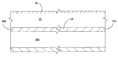
Referring to Fig. 1, a pipeline 10 that defines a passageway 10a traverses a
subterranean
formation 12. The pipeline 10 further includes a first end 10b and a second
end 10c that is separated
from the first end. In an exemplary embodiment, the pipeline 10 is positioned
below the surface 14 of
the Earth. In an exemplary embodiment, the pipeline 10 may include one or more
defects that may
necessitate repair of the pipeline by, for example, lining the interior of the
pipeline with a tubular
member.
Referring to Fig. 2, in an exemplary embodiment, in order to facilitate the
repair of the pipeline
10, the first and second ends, 10b and 10c, respectively, of the pipeline may
be exposed by removing
earthen material proxirnate the first and second ends. As a result, trenches,
16a and 16b, are
provided proximate the first and second ends, 10b and 10c, respectively, of
the pipeline 10. As a
result, the first and second ends, 10b and 1C1c, respectively, of the pipeline
10 may be accessed from
the surface 14.
Referring to Fig. 3, in an exemplary embodiment, portions of the first and
second ends, 10b
and 10c, respectively, of the pipeline 10 may then be removed by, for example,
machining away the
14
SUBSTITUTE SHEET (RULE 26)
CA 02658250 2009-01-15
WO 2008/014084 PCT/US2007/072519
portions in a convention manner. As a result, the interior passageway 10a of
the pipeline 10 may be
accessed through the resulting open ends, 10d and 1t3e, of the first and
second ends, 1flb and 10c,
respectively, of the pipeline,
Referring to Fig. 4, in an exemplary embodiment, a conventional pig 18 may
then be
positioned within the passageway 10a of the pipeline 10 through the open end
10e of the pipeline. As
will be recognized by persons having ordinary skill in the art, pigs are
commonly inserted into and
then pumped through pipelines to perforrn task such as, for example, cleaning
the interior of the
pipelines. In an exemplary embodirnent, the pig 18 sealingly engages the
interior surface of the
passageway 10a of the pipeline. An end of a tow line 20 may then be coupled to
an end of the pig 18
by passing the end of the tow line through a passageway 22a defined in an end
plate 22. In an
exemplary embodiment, a portion of the interior surface of the passageway 22a
of the end plate 22
sealingly engages the tow line 20. In an exempiary embodiment, the end plate
22 further includes an
exterior flange 22b and a transverse passageway 22c that is operably coupled
to the passageway
22a. In an exemplary embodiment, after coupling the end of the tow line 20 to
the end of the pig 18,
the exterior flange 22b of the end plate 22 is coupled to the open end 10e of
pipeline 10, and an outlet
24a of a conventional pump 24 is operably coupled to the passageway 22c of the
end plate in a
conventional manner. The other end of the tow line 20 may then be operably
coupled to a
conventional winch 26 in a conventional manner using, for example, one or more
pulleys, 28a and
28b. The pump 24 and winch 26 may be operabiy coupled to a conventional
programmable controller
30.
Referring to Fig. 5, in an exemplary embodiment, the controller 30 may then
operate the
pump 24 such that fluidic materials are discharged out of the outlet 24a of
the pump and injected into
the passageway 22c of the end plate 22 while the winch 26 is operated by the
controller to permit
movement of the tow line 20. As a result, the passageway 22a of the end plate
and the interior of the
passageway 10a of the pipeline an one side of the pig 18 are pressurized. As a
result, the pig 18, and
the end of the tow line 20 that is coupled to the end of the pig, may be
displaced in a direction 32
away from the open end 10e of the pipeiine and towards the open end 10d of the
pipeline.
Referring to Fig. 6, in an exemplary embodiment, after displacing the pig 18,
and the end of the tow
line 20 that is coupled to the end of the pig, to a position within the
passageway 10a of the pipeline 10
proximate the open end 10d, the end plate 22 may be removed and a pipe section
processing
apparatus 34 may be placed within the trench 16a proximate the open end of the
pipeline. In an
exemplary embodiment, the apparatus 34 includes a conventional pipe section
support 34a, a welding
and inspection assembly 34b, a coating assembly 34c, and an actuator 34d that
are each coupled to
a support member 34e and the controller 30.
Referring to Fig. 6a, in an exemplary embodiment, the welding and inspection
assembly 34b
includes a conventional pre-welding heat treatment device 34ba, a conventional
pipe section welder
device 34bb, a conventional post-welding heat treatment device 34bc, a
conventional weld inspection
device 34bd, and a conventional pipe section support member 34be. In an
exemplary embodiment,
the conventional pre-welding heat treatment device 34ba is adapted to provide
heat treatment of a
pipe section in a conventional manner and, may, for example, include one or
more conventional
devices for heat treating metallic pipe sections. In an exempfary embodiment,
the conventional pipe
SUBSTITUTE SHEET (RULE 26)
CA 02658250 2009-01-15
WO 2008/014084 PCT/US2007/072519
section welder device 34bb is adapted to weld together end portions of
metallic pipe sections and
may, for example, include one or more conventional devices for welding
together end portions of
metallic pipe sections. In an exemplary embodiment, the pipe section welder
device 34bb may
include one or more aspects of conventional friction stir welding. In an
exempiary embodiment, the
conventional post-welding heat treatment device 34bc is adapted to provide
heat treatment of welded
together pipe sections in a conventional manner and, may, for example, include
one or more
conventional devices for heat treating welded together metallic pipe sections.
In an exemplary
embodiment, the conventional weld inspection device 34bd is adapted to inspect
welded together
metallic pipe sections and, may, for example, include one or more conventional
devices for inspecting
welded together metallic pipe sections such as x-ray, ultrasonic, and other
non-destructive inspection
devices. In an exemplary ernbodirnent, the conventional pipe support member
34be is adapted to
convey and support metaiiic pipe sections as they are processed by the pre-
welding heat treatment
device 34ba, pipe section welder device 34bb, post-welding heat treatment
device 34bc, and weld
inspection device 34bd. In an exemplary embodiment, the welding and inspection
assembly 34b may
include one or more elements of one or more of the conventional commercially
available welding
devices commercially available from TubeFuse.
In an exemplary embodiment, one or more elements of conventional coupling
methods that
do not iriclude welding may be used in addition to, or instead of, the
conventional weld inspection
device 34bd in the welding and inspection assembly 34b.
Referring to Fig. 6b, in an exemplary embodiment, the coating assembly 34c
includes a
conventional pipe section coating device 34ca, a conventional pipe section
coating inspection device
34cb, and a conventional pipe section support member 34cc. In an exemplary
embodiment, the
conventionai pipe section coating device 34ca is adapted to apply a coating
material to the exterior
surface of a pipe section in a conventional manner and, may, for example,
include one or more
conventional devices for applying a coating material to pipe sections. In an
exemplary embodiment,
the conventional pipe section coating inspection device 34cb is adapted to
inspect coated pipe
sections and, may, for example, include one or more conventional devices for
inspecting coated pipe
sections. In an exemplary embodiment, the conventional pipe support member
34cc is adapted to
convey and support metallic pipe sections as they are processed by the pipe
section coating device
34ca and the conventional pipe section coating inspection device 34cb.
Referring to Fig. 6c, in an exemplary embodiment, the actuator assembly 34d
includes a
conventional pipe section gripper device 34da, a conventional pipe section
actuator device 34db, and
a conventional pipe section support member 34dc. In an exemplary embodiment,
the conventional
pipe section gripper device 34da is adapted to grip pipe sections in a
conventional manner and, may,
for example, include one or more conventional devices for gripping pipe
sections. In an exemplary
embodirnent, the conventional pipe section actuator device 34db is adapted to
displace pipe sections
in a longitudinal direction out of an end of the actuator assembly 34d and,
may, for example, include
one or more conventional devices for displacing pipe sections in a
longitudinal direction. In an
exemplary embodiment, the conventional pipe support member 34dc is adapted to
convey and
support metai[ic pipe sections as they are processed by the pipe section
gripper device 34da and a
conventional pipe section actuator device 34db.
16
SUBSTITUTE SHEET (RULE 26)
CA 02658250 2009-01-15
WO 2008/014084 PCT/US2007/072519
Referring to Fig. 7, in an exemplary embodiment, a pipe section 36 may then be
positioned on
the pipe section support 34a of the apparatus 34. In an exemplary embodiment,
each pipe section 36
includes a first end 36a and a second end 36b and is fabricated from a
metallic material.
Referring to Figs. 8 and 8a, 8b, 8ba, 8c, and 8d, in an exemplary embodiment,
the initial pipe
section 36 may then be moved into the welding and inspection assembly 34b and
additional pipe
sections 36 may then be sequentially positioned onto the pipe section support
34a of the apparatus
34 and also sequentially rnoved into the welding and inspection assembly. In
this manner, the pipe
sections 36 may then be processed by the welding and inspection assembly 34b.
As illustrated in Fig. 8a, in an exemplary embodiment, within the welding and
inspection
assembly 34b, the first and second ends, 36a and 36b, of the pipe sections 36
may be initially heat
treated in a conventional manner by the pre-welding heat treatment device 34ba
in order to provide
enhanced material properties within the first and second ends of the pipe
sections prior to welding the
first and second ends of adjacent pipe sections to one another in the pipe
section welder device 34bb.
As iilustrated in Fig. 8b, in an exemplary embodiment, within the welding and
inspection
assembly 34b, once adjacent pipe sections 36 are positioned within the pipe
section welder device
34bb, the first and second ends, 36a and 36b, of the adjacent pipe sections
are welded to one
another in a conventional manner. In an exemplary embodiment, as illustrated
in Fig. 8ba, as a result
of the welding operation, the entire circumference of the first and second
ends, 36a and 36b, of the
adjacent pipe sections are welded to one another forming a continuous
circumferential weld 38.
As illustrated in Fig. 8c, in an exemplary embodiment, within the welding and
inspection
assembly 34b, after the first and second ends, 36a and 36b, of the adjacent
pipe sections are welded
to one another in the pipe section welder device 34bb, the first and second
ends of the welded
together adjacent pipe sections, including the weld 38, are then heat treated
in the post-welding heat
treatment device 34bc in order to provide enhanced material properties within
the first and second
ends of the pipe sections, including the weld 38, after welding the first and
second ends of adjacent
pipe sections to one another in the pipe section welder device 34bb.
As illustrated in Fig. 8d, in an exemplary embodiment, within the welding and
inspection
assembly 34b, after the first and second ends, 36a and 36b, of the adjacent
pipe sections are heat
treated in the post-welding heat treafinent device 34bc, the first and second
ends of the pipe sections,
including the weld 38, are inspected in the weld inspection device 34bd.
Referring to Figs. 9, 9a, 9ba, 9bb and 9c, in an exemplary embodiment, further
additional pipe
sections 36 may then be sequentially positioned onto the pipe section support
34a of the apparatus
34 as pipe sections processed by the welding and inspection assembly 34b are
then processed by the
coating assembly 34c. In this manner, the pipe sections 36 may then be
sequentially processed by
the welding and inspection assembly 34b and the coating assembly 34c.
As illustrated in Figs. 9a, 9ba and 9bb, in an exemplary embodiment, within
the coating
assembly 34c, the exterior surfaces of pipe sections 36 and welds 38 are
coated with an exterior
coating layer 40 by the coating device 34ca. In an exemplary embodiment, the
layer 40 is adapted to
protect the exterior surfaces of the pipe sections 36 and welds 38 and reduce
contact friction between
the pipe sections and welds and the interior surface of the pipeline 10.
17
SUBSTITUTE SHEET (RULE 26)
CA 02658250 2009-01-15
WO 2008/014084 PCT/US2007/072519
In an exemplary embodiment, the layer 40 comprises a conventional abradable
coating
material that may provide, for example, corrosion protection and/or wear
resistance.
In an exemplary embodiment, the layer 40 comprises a plurality of layers of an
abradable
and/or lubricating coating material.
In an exemplary embodiment, the layer 40 comprises a conventional self-healing
layer of
material such that any damage to the layer caused by, for example, abrasion or
scratches, is
automatically healed.
In an exemplary embodiment, the layer 40 is a conventional environmentally
friendly layer.
As illustrated in Fig. 9c, in an exemplary embodiment, within the coating
assembly 34c, after
the pipe section 36 and welds 38 are coated with the layer 40 in the coating
device 34ca, the layer is
inspected in the coating inspection device 34cb.
Referring to Figs. 10, 10a, and 10b, in an exemplary embodiment, further
additional pipe
sections 36 may then be sequentially positioned onto the pipe section support
34a of the apparatus
34 as pipe sections processed by the welding and inspection assembly 34b and
the coating assembly
34c are then processed by the actuator assembly 34d. ln this manner, the pipe
sections 36 may then
be sequentially processed by the welding and inspection assembly 34b, the
coating assembly 34c,
and the actuator assembly 34d.
As illustrated in Figs. 1C1a and 10b, in an exemplary embodiment, within the
actuator
assembly 34d, the gripper 34da grips the pipe sections 36 and then the
actuator 34db displaces the
pipe sections 36 in a longitudinal direction out of the actuator 34d. Thus,
the actuator assembly 34d
also pulls the welded together pipe sections 36 through the end of the welding
and inspection
assembly 34b and the coating assembly 34c and thereby controls the rate at
which pipe sections 36
and welds 38 are processed.
Referring to Figs. 11 and 12, in an exemplary embodiment, the continued
operation of the
actuator assembly 34d pushes the welded together pipe sections 36 into and
through the passageway
10a of the pipeline 10 until an end 36b of a pipe section 36 engages and
couples to an end of the pig
18. Continued operation of the actuator assembly 34d then continues to push
the welded together
pipe sections 36 into and through the passageway 10a. In an exemplary
embodiment, in combination
with the operation of the actuator assembly 34d, the winch 26 is operated to
pull the pig 18 through
the passageway 1 qa of the pipeline 10. As a result of the operation of the
winch 26, the welded
together pipe sections 36 are pulled through the passageway 90a of the
pipeline 10. Thus, in an
exemplary embodiment, by operation of the actuator assembly 34d and the winch
26, the welded
together pipe sections 36 are pushed and pulled through the passageway 10a of
the pipeline 10.
In an exemplary embodiment, as illustrated in Fig. 12a, the pipe section 36
that is coupled to
the pig 18 includes a nose 37 having a first end that is coupled to an end of
the pipe section and
another tapered end 37a that is coupled to the pig. In an exemplary
embodiment, the tapered end
37a of the nose 37 includes a lubricant supply for lubricating the annular
space between nose 37
and/or the pipe sections 36 and the pipeline 10. In an exemplary embodirnent,
during operation, the
nose 37 reinforces the structure of one or more of the pipe sections 36 and
thereby substantially
prevents one or more of the pipe sections 36 from being deformed to, for
example, an oval outer
profile.
18
SUBSTITUTE SHEET (RULE 26)
CA 02658250 2009-01-15
WO 2008/014084 PCT/US2007/072519
Referring to Fig. 13, in an exemplary embodiment, the continued operation of
the actuator
assembly 34d and the winch 26 displaces the pipe sections 36 out of the end
10e of the pipeline and
into the trench 16b, In an exemplary embodiment, the pig 18 may then be
decoupled from an end of
one of the pipe sections 36 and removed from the trench 16b. Subsequent
continued operation of the
actuator assembly 34d may then displace at least a portion of the pipe
sections 36 into an open end
of the second end 10c of the pipeline 10.
In an exemplary embodiment, the insertion and placement of the pipe sections
36 within the
pipeline may include one or more aspects of the conventional methods of
sliplining and/or
swagelining.
Referring to Figs. 14 and 15, in an exemplary embodiment, after the pipe
sections 36 have
been positioned within the entirety of the length of the passageway 10a of the
pipeline 10 between the
trenches, 16a and 16b, the apparatus 34 may be removed from the trench 16a and
an expansion
system 42 may be positioned within the trench proximate the open end 10d of
the pipeline. In an
exemplary embodiment, the expansion system 42 includes a pump 42a that is
operably coupled to an
expansion device 42b and the controller 30. ln an exemplary embodiment, the
pump 42a and
expansion device 42b are mounted upon a support member 42c.
In an exemplary embodiment, the expansion device 42b includes a tubular
launcher 42ba that
defines a chamber 42baa having a first tubular portion 42bab, a second tubular
portion 42bac, and an
intermediate tapered tubular portion 42bad. In an exemplary embodiment, an end
of the first tubular
portion 42bab of the tubular launcher 42ba of the expansion device 42b is
coupled to an end plate
42bb that defines a passage 42bc and an end of the second tubular portion
42bac of the tubular
launcher 42ba of the expansion device 42b is coupled to an end of one of the
pipe sections 36. In an
exemplary embodiment, each pipe section 36 defines a passageway 36c. In an
exemplary
embodiment, an outlet of the pump 42a is operably coupled to the passage 42bc
of the end plate
42bb of the expansion device 42b. In an exemplary embodiment, an expansion
cone 42bc that
includes a tapered exterior surface 42bca is positioned within the chamber
42baa and mates with the
interior surfaces of the tubular launcher 42ba. In an exemplary embodiment,
the interface between
the expansion cone 42bc and the interior surfaces of the tubular launcher 42ba
is not fluid tight in
order to facilitate lubrication of the interface.
Referring to Figs. 16 and 17, in an exemplary embodiment, the pump 42a may
then be
operated by the controller 30 to inject fluidic materials into the chamber
42baa of the tubular launcher
42ba of the expansion device 42b. As a result, the expansion cone 42bc may be
displaced
longitudinally relative to the end plate 42bb thereby causing the tapered
external surface 42bca of the
expansion cone to engage and thereby radially expand and plastically deform
the tapered tubular
portion 42bad and second tubular portion 42bac of the tubular launcher 42ba.
In an exempiary
embodiment, continued injection of the fluidic materials into the chamber
42baa will then further
displace the expansion cone 42bc in a longitudinal direction thereby causing
the expansion cone to
radially expand and plastically deform one or more of the pipe sections 36.
Referring to Figs. 18 and 18a, in an exemplary embodiment, continued injection
of the fluidic
materials into the chamber 42baa wili then further displace the expansion cone
42bc thereby causing
the expansion cone to radially expand and piastically deform all of the pipe
sections 36 positioned
19
SUBSTITUTE SHEET (RULE 26)
CA 02658250 2009-01-15
WO 2008/014084 PCT/US2007/072519
within the pipeline 10. In an exemplary embodiment, each pipe section 36 is
expanded into contact
with the surrounding portion of the pipeline 10. In an exemplary embodiment,
at least a portion of the
surrounding pipeline 10 is radially expanded and elastically and/or
plastically deformed by the radial
expansion and plastic deformation of the pipe sections 36.
In an exemplary embodiment, the radial expansion and plastic deformation of
the pipe
sections 36 into engagement with the pipeline 10 results in a resulting
pipeline assembly, including
the combination of the pipeline and the radially expanded and plastically
deformed pipe sections,
having a capacity to convey fluidic materials such as, for example, natural
gas and/or fuel oil, at
increased operating pressures and/or flow rates versus the pipeline 10 by
itself. In this manner, the
present exemplary embodiments provide a methodology for up-rating preexisting
underground
pipelines to convey fluidic materials at increased flow rates and/or operating
pressures. In an
exernplary embodiment, the up-rating of the pipeline 10 may be provided with
or without any radial
deforr'natian of the pipeline.
Referring to Figs. 19 and 20, in an exemplary embodiment, after all of the
pipe sections 36
positioned within the pipeline 10 have been radially expanded and plastically
deformed, the expansion
cone 42bc may be removed from the pipe sections, the expansion system 42 may
be decoupled from
the pipe sections 36 and removed from the trench 16a, an end plate 44 may be
coupled to a radially
expanded end of a pipe section 36 within the trench 16b, and an end plate 46
that defines a
longitudinal passage 46a may be coupled to a radially expanded end of a pipe
section within the
trench 16a.
In an exemplary embodiment, an outlet of a pump 48 that is operably coupled to
the controller
may then be operably coupled to the passage 46a of the end plate 46. In an
exemplary
embodiment, the pump 48 may then be operated to inject fluidic materials into
the pipe sections 36 to
thereby pressurize the pipe sections. In an exemplary embodiment, during the
pressurization of the
25 interior of the pipe sections 36, the operating pressure is monitored by
the controller 30 to thereby
determine the integrity and condition of the pipe sections.
Referring to Figs. 21 and 22, after completing the pressure testing of the
pipe sections 36, the
end plates, 46 and 48, may be removed from the ends of the corresponding pipe
sections. In an
exemplary embodiment, after removing the end plates, 46 and 48, from the ends
of the corresponding
30 pipe sections, transitionary pipe sections, 50a and 50b, may be installed
in a conventional manner
between the ends of the radially expanded and plastically deformed ends of the
pipe sections 36 and
the open ends, 10b and 10c, respectively, of the pipeline 10. As a result,
fluidic materials may then
be transported through the pipeline 10, radially expanded pipe sections 36,
and the transitionary pipe
sections, 50a and 50b.
Referring to Figs. 23 and 24, in an exemplary embodiment, after installing the
transitionary
pipe sections, 50a and 50b, the trenches, 16a and 16b, may be filled with
earthen materiai thereby
burying the radially expanded pipe sections 36 and the transitionary pipe
sections, 50a and 50b,
within the respective trenches beneath the surface 14 of the Earth.
Thus, the operational steps of Figs. 1-24 result in a methodology for
repairing the pipeline 10.
In an exemplary embodiment, one or more of the pipe sections 36 may be
fabricated from other
materials such as, for example, plastics and/or composite materials and the
apparatus 34 may be
SUBSTITUTE SHEET (RULE 26)
CA 02658250 2009-01-15
WO 2008/014084 PCT/US2007/072519
rnodified using cornbinations of conventional joining systems for joining
metallic, plastic and/or
composite materials to one another.
In an exemplary embodiment, one or more portions of the pipeline 10 may be
uncovered and
then pipe sections 36 may be inserted into the pipeline and processed using
one or more of the
operational steps of the method of Figs. 1-24.
Referring to Figs. 25a and 25b, in an exemplary embodiment, pipe sections 2500
that include
a corrugated cross section 2500a may be employed in place of, or in addition
to, one or more of the
pipe sections 36 in the method of Figs. 1-24 above. In an exemplary
embodiment, the expansion
forces required to radially expand the pipe sections 2500 may be substantially
less than the
expansion forces required to radially expand the pipe sections 36. Thus, use
of the pipe section 2500
in the method of Figs. 1-24 above may result in reduced overall expansion
forces and thereby may
save time and money.
Referring to Fig. 26, in an exemplary ernbodiment, in the method of Figs. 1-24
above, one or
rnare portions of one or more of the pipe sections 36 may not be radially
expanded and plasticaffy
deforrned. In addition, referring to Fig. 26, in an exemplary embodiment, in
the method of Figs. 1-24
above, one or more portions of one or more of the pipe sections 36 may not be
radiafly expanded and
plastically deformed into engagement with the surrounding portions of the
pipeline 10.
Referring to Figs. 27 and 27a, in an exemplary embodiment, pipe sections 2700
that include
one or more outer sealing fayers 2700a may be employed in place of, or in
addition to, one or more of
the pipe sections 36 in the method of Figs. 1-24 above. In an exemplary
embodiment, one or more of
the outer sealing layers 2700a may, for example, seal the interface between
the pipe section 2700
and the corresponding outer portion of the pipeline 10. In an exemplary
embodiment, one or more of
the outer sealing layers 2700a may, for example, provide cathodic protection
of the pipe section 2700
and/or the corresponding outer portion of the pipeline 10.
In an exemplary embodiment, following the radial expansion and plastic
deformation of the
pipe sections 36 within the pipeline 10, at least a portion of the one or more
of the pipe sections form
a metal to metal seal with at least a portion of the pipeline.
Referring to Fig. 28, in an exemplary embodiment, an expansion device 2800 may
be used in
the method of Figs. 1-24 above that is substantiaify identical to the
expansion device 42b with the
exception of the use of an adjustable expansion device 2802 instead of the
expansion cone 42bc. In
an exemplary embodiment, the adjustable expansion device 2802 is a
conventional adjustable
expansion device and/or one or more of the adjustable expansion devices
included in one or more of
the applications and patents incorporated by reference into the present
application.
Referring to Fig. 29, in an exemplary embodiment, an expansion device 2900 may
be used in
the method of Figs. 1-24 above that is substantially identical to the
expansion device 42b with the
exception of the use of an adjustable expansion device 2902 and a fixed
expansion device 2904
instead of the expansion cone 42bc. ln an exemplary embodiment, the adjustable
expansion device
2902 is a conventional adjustable expansion device and/or one or more of the
adjustable expansion
devices included in one or more of the applications and patents incorporated
by reference into the
present application. In an exemplary embodiment, the fixed expansion device
2904 is a conventional
21
SUBSTITUTE SHEET (RULE 26)
CA 02658250 2009-01-15
WO 2008/014084 PCT/US2007/072519
adjustable expansion device and/or one or more of the adjustable expansion
devices included in one
or more of the applications and patents incorporated by reference into the
present application.
Referring to Fig. 30, in an exemplary embodiment, an expansion device 3000 may
be used in
the method of Figs. 1-24 that includes a gripper 3002 for controllably
gripping an interior surface of the
pipe sections 36 that is coupled to an end of an actuator 3004. ln an
exemplary embodiment, another
end of the actuator 3004 is coupled to an expansion device 3006.
In an exemplary embodiment, during operation of the expansion device 3000, the
gripper
3002 engages the internal surfaces of a radially expanded and plastically
deformed pipe section 36
and the actuator 3004 operates to displace the expansion device 3006 in a
longitudinal direction away
from the gripper thereby radially expanding and plastically deforming the pipe
section 36. In an
exemplary embodiment, the gripper 3002 is a conventional gripping device
and/or one or more of the
gripping devices included in one or more of the applications and patents
incorporated by reference
into the present application. In an exemplary embodiment, the actuator 3004 is
a conventional
actuator and/or one or more of the actuators included in one or more of the
applications and patents
incorporated by reference into the present application. In an exemplary
embodiment, the expansion
device 3006 is a conventional expansion device and/or one or more of the
expansion devices
included in one or more of the applications and patents incorporated by
reference into the present
application.
Referring to Fig. 31, in an exemplary embodiment, an expansion device 3100 may
be used in
the method of Figs. 1-24 that includes an expansion device 3102, an actuator
3104, and a gripper
3106.
In an exemplary embodiment, during operation of the expansion device 3100, the
gripper
3106 engages the internal surfiaces of a pipe section 36 and the actuator 3104
operates to displace
the expansion device 3102 in a longitudinal towards from the gripper thereby
radially expanding and
plastically deforming the pipe section 36. In an exemplary embodiment, the
expansion device 3102 is
a conventional expansion device and/or one or more of the expansion devices
included in one or
more of the applications and patents incorporated by reference into the
present application. In an
exemplary embodiment, the actuator 3104 is a conventional actuator and/or one
or more of the
actuators included in one or more of the applications and patents incorporated
by reference into the
present application. in an exemplary embodiment, the gripper 3106 is a
conventional gripping device
and/or one or more of the gripping devices included in one or more of the
applications and patents
incorporated by reference into the present application.
Referring to Fig. 32, in an exemplary embodiment, an expansion device 3200 may
be used in
the method of Figs. 1-24 above that is substantiaily identical to the
expansion device 42b with the
exception of the use of a compliant expansion device 3202 instead of the
expansion cone 42bc. In an
exemplary embodiment, the compliant expansion device 3202 is a conventional
compliant expansion
device and/or one or more of the adjustable expansion devices included in one
or more of the
applications and patents incorporated by reference into the present
application.
Referring to Fig. 33, in an exemplary embodiment, an expansion device 3300 may
be used in
the method of Figs. 1-24 that includes a tractor 3302 and an expansion device
3304.
22
SUBSTITUTE SHEET (RULE 26)
CA 02658250 2009-01-15
WO 2008/014084 PCT/US2007/072519
In an exemplary embodiment, during operation of the expansion device 3300, the
tractor 3302
drives along the interior of the pipe sections 36. As a resuit, the expansion
device 3304 coupled to
the tractor 3302 is pushed by the tractor within the pipe sections in a
longitudinal direction thereby
radially expanding and plastically deforming the pipe section 36. In an
exemplary embodiment, the
tractor 3302 is a conventional tractor and/or one or more of the tractors
included in one or more of the
applications and patents incorporated by reference into the present
application. In an exemplary
embodiment, the expansion device 3304 is a conventional expansion device
and/or one or more of
the expansion devices included in one or more of the applications and patents
incorporated by
reference into the present application.
Referring to Fig. 34, in an exemplary embodiment, an expansion device 3400 may
be used in
the method of Figs. 1-24 that includes an expansion device 3402 and a tractor
3404.
In an exemplary embodiment, during operation of the expansion device 3400, the
tractor 3402
drives along the interior of the pipe sections 36. As a result, the expansion
device 3402 coupled to
the tractor 3404 is pulled by the tractor within the pipe sections in a
longitudinal direction thereby
radially expanding and plastically deforming the pipe section 36. In an
exemplary embodiment, the
expansion device 3402 is a conventional expansion device and/or one or more of
the expansion
devices included in one or more of the applications and patents incorporated
by reference into the
present application. In an exemplary embodiment, the tractor 3404 is a
conventional tractor and/or
one or more of the tractors included in one or more of the applications and
patents incorporated by
reference into the present application.
Referring to Fig. 35, in an exemplary embodiment, an expansion device 3500 may
be used in
the method of Figs. 1-24 that includes a pump 3502 and an expansion device
3504.
In an exemplary embodiment, during operation of the expansion device 3500, the
interior
portion of the pipe section 36 is at least partially filled with a fluidic
material and the pump 3502 is
operated to discharge fluidic materials in a longitudinal direction away from
the pump. As a result, the
expansion device 3504 coupled to the pump 3502 is pushed through the pipe
section 36 in a
longitudinal direction thereby radially expanding and plastically deforming
the pipe section 36. In an
exemplary embodiment, the expansion device 3504 is a conventional pump and/or
one or more of the
expansion devices included in one or more of the applications and patents
incorporated by reference
into the present application.
Referring to Figs. 36a and 36b, in an exemplary ernbodiment, an expansion
device 3600 may
be used in the method of Figs. 1-24 that includes a vibration device 3602
coupled to an expansion
device 3604.
In an exemplary embodiment, during operation of the expansion device 3600, the
vibration
device 3602 is operated while the expansion device 3604 is displaced in a
longitudinal direction within
the pipe sections 36. As a result, the expansion device 3604 radially expands
and plastically deforms
the pipe section 36. Furthermore, in an exemplary embodiment, the expansion
device 3604 also
radially expands and plasticafly deforms defects 3704 within the pipeline 10
such as, for example,
collapsed portions of the pipeline. In an exemplary errGbodiment, the
vibration device 3602 is a
conventional vibration device and/or one or more of the vibration devices
included in one or more of
the applications and patents incorporated by reference into the present
application. In an exemplary
23
SUBSTITUTE SHEET (RULE 26)
CA 02658250 2009-01-15
WO 2008/014084 PCT/US2007/072519
embodiment, the expansion device 3604 is a conventional expansion device
and/or one or more of
the expansion devices included in one or more of the applications and patents
incorporated by
reference into the present application.
Referring to Figs. 37a and 37b, in an exemplary embodiment, an expansion
device 3700 may
be used in the method of Figs. 1-24 that includes a controller 3702 coupled to
a rotary expansion
device 3704.
In an exemplary embodiment, during operation of the expansion device 3700, the
controller
3702 is operated to rotate and longitudinally displace the rotary expansion
device 3704 within the pipe
sections 36. As a result, the rotary expansion device 3704 radially expands
and plastically deforms
the pipe section 36. Furthermore, in an exemplary embodiment, the expansion
device 3704 also
radially expands and plastically deforms defects 3706 within the pipeline 10
such as, for example,
collapsed portions of the pipeline. In an exemplary embodiment, the controller
3702 is a conventional
controller and/or one or more of the controller devices included in one or
more of the applications and
patents incorporated by reference into the present application. In an
exemplary embodiment, the
rotary expansion device 3704 is a conventional expansion device and/or one or
more of the rotary
expansion devices included in one or more of the applications and patents
incorporated by reference
into the present application.
Referring to Fig. 38, in an exemplary embodiment of an actuator 3800 is
substantially
identical to the actuator 34d with the addition of a vibration source 3802
that is operably coupled to
the gripper 34da. In an exemplary embodiment, the actuator 3800 may be
substituted for, or used in
addition to, the actuator 34d in the method of Figs. 1-24 described above. In
an exemplary
embodiment, during the operation of the actuator 3800, the vibration source
3802 injects vibratory
energy into the pipe sections 36 thereby reducing the level of contact
friction between the pipe
sections and the pipeline 10.
Referring to Fig. 39, in an exemplary embodiment of an actuator 390Ã3 is
substantially
identical to the actuator 34d with the substitution of an actuator 3902 that
may impart longitudinal and
rotational displacement to the pipe sections 36. In an exemplary embodiment,
the actuator 3900 may
be substituted for, or used in addition to, the actuator 34d in the method of
Figs. 1-24 described
above. In an exemplary embodiment, during the operation of the actuator 3900,
the actuator 3902
imparts longitudinal and rotational displacement to the pipe sections 36
thereby reducing the level of
contact friction between the pipe sections and the pipeline 10.
Referring to Figs. 40, 40a, 40b, and 40c, in an exemplary embodiment, during
operation of
the method of Figs. 1-24 described above, the interface between the pipe
sections 36 and the pipeiine
10 is filled with one or more of the following: a) a fluidic material 4002, b)
a spider support 4004,
and/or c) a dissolvable bearing material 4006.
In an exemplary embodiment, use of the fluidic material 4002 within the
interface between the
pipe sections 36 and the pipeline 10, permits the pipe sections to be floated
through the pipeline
thereby reducing contact friction between the pipe sections and the pipeline.
In an exemplary
embodiment, once the pipe sections 36 are positioned to their desired final
positions, the fluidic
material 4002 may be drained out of the interior of the pipeline 10.
24
SUBSTITUTE SHEET (RULE 26)
CA 02658250 2009-01-15
WO 2008/014084 PCT/US2007/072519
In an exemplary embodiment, the spider support 4006 includes bearing surfaces
for
supporting the pipe sections 36 away from the interior surface of the pipeline
10. ln this manner,
contact friction between the pipe sections 36 and the pipeline 10 may be
reduced. In an exemplary
embodiment, the spider support 4004 may be, for example, a conventional spider
support structure.
In an exemplary embodirnent, once the pipe sections 36 are positioned to their
desired final positions,
the spider support 4006 may be removed from the interior of the pipeline 10.
In an exemplary embodiment, the bearing material 4008 provides bearing
surfaces for
supporting the pipe sections 36 away from the interior surface of the pipeline
10. In this manner,
contact friction between the pipe sections 36 and the pipeline 10 may be
reduced. In an exemplary
embodiment, the bearing material 4008 may be, for example, a dissolvable
bearing material such as
ice.
Referring to Fig. 41, in an exempiary embodiment, during operation of the
method of Figs. 1-
24 described above, one or more of the pipe sections 36d may be bent about a
radius of curvature R
while being positioned within the pipeline 10, prior to be being radialiy
expanded and plasticaffy
deformed. In an exemplary embodiment, the bending of the pipe section 36d
results in a piastic
deformation of the pipe section 36b.
In an exemplary experimental embodiment, pipe sections 36d were bent about a
radius and
then radially expanded and plastically deformed without any failure of the
pipe section. This was an
unexpected result.
Referring to Figs. 42a and 43b, in an exemplary embodiment, during operation
of the method
of Figs. 1-24 described above, a sMart pig 4200 may be pumped through the
pipeline 10 prior to
placing the pipe sections 36 within the pipeline in order to inspect the
pipeline.
In particular, as illustrated in Fig. 42a, the pig 4200 may be inserted into
an end of the pipe
sections 36 that extend into the trench 16a and an end plate 4202 that defines
a passage 4202a
coupled the end of the pipe sections. A pump 4204, mounted upon a support
member 4206, may
then be positioned within the trench 16a and the outlet of the pump operably
coupled to the passage
4202a of the end plate 4202. The pump 4204, under the control of the
controller 30, may then be
operated to displace the pig 4200 through the pipeline 10.
In an exemplary embodiment, as illustrated in Fig. 42b, the pig 4200 includes
an inspection
tool 4200a and a pipe preparation tool 4200b. ln an exemplary embodiment,
during operation of the
pig 4200, under the control of the controller 30, the inspection tool 4200a
inspects the pipeline 10 and
the preparation tool 4200b prepares the interior surface of the pipeline for
subsequent insertion of the
pipe sections 36. In an exemplary embodiment, the inspection tool 4200a may
include a conventional
pipe inspection tool and the pipe preparation tool 4200b may include a
conventional pipe preparation
tool.
Referring to Figs. 43a, 43b, 43c, and 43d, an exemplary embodiment of a pipe
repair tool
4300 inciudes a tractor 4300a, an expansion device 4300b, and an inspection
tool 4300c. In an
exemplary embodiment, the tractor 4300a is adapted to move the tool 4300
through the interior of the
pipeline 10 and may, for example, include a conventional tractor device. In an
exemplary
embodiment, the expansion device 4300b includes a tubular liner 4300ba and is
adapted to radially
expand and plasticai[y deform the tubular liner 4300ba into engagement with a
portion of the pipeiine
SUBSTITUTE SHEET (RULE 26)
CA 02658250 2009-01-15
WO 2008/014084 PCT/US2007/072519
10. In an exemplary embodiment, the inspection tool 4300c is adapted to
inspect the pipeline 10 and
locate defects 4302 in the pipeline.
In an exemplary embodiment, during operation of the tool 4300, under the
control of the
controller 30, the tractor 4300a moves the tool through the pipeline 10. While
the tool 4300 is moved
through the pipeline 10, the inspection tool 4300c identifies and locates
defects 4302 in the pipeline.
The expansion tool 4300b is then positioned proxirnate the located defects
4302 and is operated to
radially expand and plastically deform the tubular liner 4300ba into
engagement with the pipeline 10 in
opposing relation to the defect. In this manner, defects 4302 within the
pipeline 10 may be repaired.
Referring to Fig. 44, in an exemplary embodiment, during operation of the
method of Figs. 1-
24 described above, one or more of the pipe sections 36 may include an
interior coating 4400 of a
lubricating material in order to reduce the required expansion forces during
the radial expansion and
plastic deformation of the pipe sections.
Referring to Figs. 45a, 45b, 45c, and 45d, in an exemplary embodiment, during
operation of
the method of Figs. 1-24 described above, after the pipe sections 36 are
positioned within the pipeline
10, an end cap 4500 that defines a passage 4500a is coupled to an end of the
pipe sections within the
trench 16a and an end cap 4502 is coupled to an end of the pipe sections
within the trench 16b. An
outlet of a pump 4504 is then operably coupled to the passage 4500a of the end
cap 4500.
In an exemplary ernboc3iment, the pump 4504, under the control of the
controller 30, is then
operated to pressurize the interior 36c of the pipe sections 36 and thereby
hydroform the pipe section
thereby radially expanding and plastically deforming the pipe sections into
engagement with the
pipeline 10.
Referring to Figs. 46a, 46b, 46c, and 46d, in an exemplary embodiment, during
operation of
the method of Figs. 1-24 described above, after the pipe sections 36 are
positioned within the pipeline
10, a conventional explosive device 4600 is positioned within the interior 36c
of the pipe sections.
End caps 4602 and 4604 are then coupled to the opposing ends of the pipe
sections 36 within the
trenches, 16a and 16b, respectively.
In an exemplary embodiment, the explosive device 4600, under the control of
the controller
30, is then detonated within the interior 36c of the pipe sections 36 and
thereby radially expands and
plastically deforms the pipe sections into engagement with the pipeline 10.
Referring Figs. 47, in an exemplary embodiment, during operation of the method
of Figs. 1-24
described above, during the radial expansion and plastic deformation of the
pipe sections 36, at least
one pipe section 36e within the trench 16b is adapted to provide an indication
of the radial expansion
and plastic deformation of pipe sections within the trench 16b. In an
exemplary embodiment, the
indication may be a visual indication and/or a pressure indication. For
example, the pipe section 36e
may be coated with a stress sensitive coating that changes color when
strained. For example, the
pipe section 36e may include one or more perforations such that a noticeable
pressure drop may be
observed when the pipe section 36 is radiaiiy expanded and plastically
deformed.
Referring Fig. 48, in an exemplary embodiment, during operation of the method
of Figs. 1-24
described above, during the insertion of the pipe sections 36 into the
pipeline, an end plate 4800 is
coupled to an end of the pipe sections 36 and outlet of a pump 4800, under the
control of the
controller 30, is operably directed into an open end of an end most one of the
pipe sections extending
26
SUBSTITUTE SHEET (RULE 26)
CA 02658250 2009-01-15
WO 2008/014084 PCT/US2007/072519
into the trench 16a. In this manner, the fluid pressure directed into the open
end of the end most of
the pipe sections 36 within the trench 16a drives the pipe sections into the
pipeline 10.
Referring Fig. 49, in an exemplary embodiment, during operation of the method
of Figs, 1-24
described above, during the insertion of the pipe sections 36 into the
pipeline, an end of a
conventional tractor 4900, under the control of the controller 30, is coupled
to an end of the pipe
sections 36 operated to pull the pipe sections through the interior of the
pipeline 10.
Referring Fig. 50, in an exemplary embodiment, during operation of the method
of Figs. 1-24
described above, at least a portion of the pipeline 10 is lined with a
plurality of pipe sections, 5002 and
5004, that are substantially identical to the pipe sections 36. In this
manner, the pipeline 10 may be
lined with a multi-layer liner whose collapse strength may thereby be adjusted
by varying the number
and type of liners installed within the pipeline.
in an exemplary embodiment, the radial expansion and plastic deformation of
the pipe
sectians 5002 and 5004 into engagement with the pipeline 10 results in a
resulting pipeline assembly,
including the combination of the pipeline and the radially expanded and
plastically deformed pipe
sections, having a capacity to convey fluidic materials such as, for example,
natural gas and/or fuel
oil, at increased operating pressures and/or flow rates versus the pipeline 10
by itself. In this manner,
the present exemplary embodiments provide a methodology for up-rating
preexisting underground
pipelines to convey fluidic materials at increased flow rates and/or operating
pressures. In an
exemplary embodiment, the up-rating of the pipeline 10 may be provided with or
without any radial
deformation of the pipeline.
Referring Fig. 51, in an exemplary embodiment, during operation of the method
of Figs. 1-24
described above, a coiled tubing 5100 may be installed in the pipeline 10
using a conventional pipe
reel 5102 under the control of the controller 30. In this manner, a seamless
liner may be used and
thereby the need to weld together pipe sections may be eliminated.
In an exemplary embodiment, the tubing 5100 may be fabricated from one or more
of the
following: metallic materials, non-metallic materials, plastics, composites,
ceramics, porous materials,
non-porous materials, perforated materials, non-perforated materials, and/or
hardenable fluidic
materials.
Referring Fig. 52, in an exempiary embodiment, during operation of the method
of Figs. 1-24
described above, a heater 5200 may be operated by the confroiier 30 to heat
the pipeline 10 during
the radial expansion and plastic deformation of the pipe sections 36. In an
exemplary embodiment,
upon the completion of the radial expansion and plastic deformation of the
pipe sections 36, the
operation of the heater 5200 may be stopped by the controller 30. As a result,
during the radial
expansion and plastic deformation of the pipe sections 36, the heated pipeline
10 will radially expand
in size. Following the completion of the radial expansion and plastic
deformation of the pipe sections
36, the pipeline 10 will then cool and thereby shrink. As a result, the joint
between the pipeline 10 and
the radially expanded and plastically deformed pipe sections 36 will be an
interference fit.
In an exemplary embodiment, more generally, energy such as, for example,
thermal energy,
acoustic energy, or electrical energy may be injected into the pipeline 10
and/or the pipe sections 36
during the radial expansion and plastic deformation of the pipe sections in
order to facilitate the radial
expansion of the pipeline. In this manner, in an exemplary embodiment, an
interference fit may be
27
SUBSTITUTE SHEET (RULE 26)
CA 02658250 2009-01-15
WO 2008/014084 PCT/US2007/072519
formed between the pipeline 10 and the pipe sections 36 such that the pipeline
remaining in
circumferential tension and the pipe sections remain in circumferential
compression following the
completion of the radial expansion process.
In an exemplary embadiment, the injection of the energy into the pipeline 10
may also
facilitate the rupture of the pipeline during the radial expansion and plastic
deformation of the pipe
sections 36. In this manner, the amount of energy required to radially expand
and plastically deform
the pipe sections 36 may be reduced.
Referring Fig. 53, in an exemplary embodiment, during operation of the method
of Figs. 1-24
described above, the pipe sections 36 may be radially expanded at both ends.
Referring to Fig. 54, in an exemplary ernbodirnent, during operation of the
method of Figs. 1-
24 described above, portions of the pipeline 10 between the trenches 16a and
16b is also radially
expanded. In an exemplary embodiment, the inside diameter of the radially
expanded pipe sections
36 is substantially equal to the inside diameter of the portions, 10b and 10c,
of the pipeline 10. In this
manner, the cross sectional area of the pipeline 10 following the repair is
substantially equal to the
cross sectional area of the pipeline prior to the repair.
In an exemplary embodiment, one or more of the pipe sections, 36 and/or 5100,
may include
perfcarations.
In an exemplary embodiment, one or more of the pipe sections, 36 and/or 5100,
may include
spirally wound elements.
In an exemplary experimental embodiment, as illustrated in Fig. 55, three-
dimensional ("3l)")
finite element analyses ("FEA") using a conventional FEA software program,
that was predicative of
actual experimental results, was performed using a model 5500 in which a
tubular member 5502 was:
1) inserted into an outer tubular member 5504 having a bend radius 5506; and
then 2) the tubular
member 5502 was radially expanded and plastically deformed within the outer
tubular member 5504
by displacing a solid expansion cone through the tubular member 5502 using
fluid pressure that
generated the following tabular results for model cases 5500A, 55008, 5500C,
5500D, and 5500E:
Friction '
Coefficient Friction
Between Coefficient
The Between The
Tubular Expansion
Member Cone and the'
5502 and Tubular
the Tubular Member Percent Radiai
Model Expansion Pressure 5504 Member 5502 C7 The uring Expansion Of The Bend
Radius
Case (psi) During isplacemen Tubular Member 5506
lInsertion Of Of The 5502 (
~ ~
The Expansion
Tubular Cone
Member Relative To
55021fVithinà the Tubular
Insertion Expansion; the Tubuiar~ Member
Force Force Member 5502
Kips (Kips) 5504
15500A 54.1 393.4 3421 0.20 0.13 20.0 20 [Oe rees
15500B; 38.8 299.0 2600 0.13 0.07 20.0 20 Qe rees
28
SUBSTITUTE SHEET (RULE 26)
CA 02658250 2009-01-15
WO 2008/014084 PCT/US2007/072519
mmmm~ ~~ i Friction
Coefficient ? Friction
i Between Coefficienf
~ The Between The'
Tubular Expansion
Member Cone and the
5502 and Tubular
the Tubulari Member Percent Radial
Model Expansion Member 5502 During
Expansion Of The Bend Radius
Pressure 5504 The
Case (psi) During isplacemen Tubular Member mber 5506
Insertion Of Of The 5502 (~ ~
The Expansion
Tubular Cone
Member Relative To
5502 Within the Tubular
Insertion Expansion the Tubular Member
Force Force Member 5502
[
(Kips) ~Kips) 5504
155000 71.9 321.5 2796 0.20 0.13 15.0 20De rees
; _ - - -
550t7Di 30.8 393.4 3421 0.20 0.13 20.0 30 f7e rees
55U0L: 12t3. / 854.3 7429 0.20 0.13 20.0 20 Degrees
Case 5500A was the base case which simulated actual laboratory testing
conditions. For
case 5500A, the wall thickness of the tubular mernber 5500 was 0.307". Due to
the higher friction
coefficients used in case 5500A, the predicted expansion forces and pressures
were much higher
than the laboratory test results.
Case 5500B was substantially identical to case 5500A except that the
coefficient of friction
between the expansion cone and the tubular member 5502 was reduced from 0.13
to 0.07. Case
5500B had lower friction coefficients than case 5500A. And, as expected, the
expansion pressure
and forces for case 5500B were much lower than for case 5500A. The laboratory
test had an
expansion pressure of 2030 psi compared to 2600 psi for case 5500B. The higher
predicted pressure
for case 5500B was also due to the addition of an outer layer of a
subterranean formation that was
simulated in case 5500B that added a restraining condition to the outer
tubular member 5504 in case
5500B.
Case 5500C was substantially identical to case 5500A except that the
diametrical clearance
between the tubular members, 5500 and 5502, was reduced and the percentage of
the radial
expansion of the tubular member 5500 was reduced from 20% to 15%. Because case
5500C had a
smaller diametrical clearance between the inner tubular member 5502 and the
outer tubular member
5504, the possible percentage radial expansion ratio for the inner tubular
member 5502 was lower.
The expansion pressures and forces were also lower than for case 5500A.
Case 5500D was substantially identical to case 5500A, except that the bend
radius 5506 of
the tubular member 5504 was increased from 20 degrees to 30 degrees. Note that
the expansion
pressure and force for case 5500D was substantially the same as for case
5500A. This experimental
result indicated that the dimension of the bend radius 5506 had no effect on
the expansion pressure.
This was an unexpected result.
Case 5500E was substantially identical to case 5500A, except that the wall
thickness of the
tubular member 5502 was increased from 0.307" to 0.625'. Case 5500E had the
highest insertion
force and expansion pressure due to the thick wall thickness of the tubular
member 5502.
29
SUBSTITUTE SHEET (RULE 26)
CA 02658250 2009-01-15
WO 2008/014084 PCT/US2007/072519
Further graphical results for cases 5500A, 5500B, 5500C, 5500D, and 5500E are
presented in Figs.
56 and 57. Note that the expansion force for case 5500D was substantiaiiy the
same as for case
5500A. This experimental result indicated that the dimension of the bend
radius 5506 had no effect
on the expansion pressure. This was an unexpected result.
Based upon the experimental results for cases 5500A, 5500B, 5500C, 5500D, and
5500E, the
fofiowing observations can be made: the bend radius 5506 has an effect on the
insertion force but
does not affect the expansion force or pressure. This was an unexpected
result_ Furthermore, this
indicates that the systems of the present iliustrative embodiments may be
operated to radially expand
a given tubular member positioned within an outer tubular member using
substantially constant
expansion forces and/or pressures for any bend radius or combination of bend
radiuses of the outer
tubular member. In addition, the unexpected exemplary experimental results
further indicated that the
radial expansion and plastic deformation of the pipe section 36 within a
pipeline 10 having one or
more bend radiuses was both feasible and commercialiy viable.
In an exemplary experimental embodiment, three-dimensional ("3D") finite
element analyses
( FEA") using a conventional FEA software program, that was predicative of
actual experimental
results, were performed using models 5800A and 58008, each having an inner
tubular member 5802
and an outer tubular member 5804 having the following properties:
Inner Tubular Member 5802
Pro ert Value Unit Value Unit
Outer diameter 11.25 in 285.7 mm
Inner diameter 10 in 254.0 mm
Linear weight 64.43 lb/ft Wall thickness 0.625 in 15.87 mm
L?lt - ratio 18 - - -
Cross section area 20.86 in 13458 rnm
42 ksi 289 MPa
Yield strength
Ultimate stren th ; 60 ksi 413 MPa
Outer Tubular Member 5804
Pro ert Value Unit Value Unit
Inner diameter 12 in 304.8 mm
Outer diameter 12_78 in 305.5 mm
Wall thickness 0.394 in 10 mm
Yield stren th 42 ksi 289 MPa
Ultimate stren th 60 ksi 413 MPa
Ultimate burst 3820 si 26 MPa
In a model 5800A, as illustrated in Fig. 58a, the inner tubular member 5802
was inserted into
the outer tubular member 5804 in which the outer tubular member 5804 did not
include any bend
radius.
In model 5800B, as illustrated in Fig. 58b, the inner tubular member 5802 was
inserted into
the outer tubular member 5804 in which the outer tubular member 5804 included
a curved portion
5804a. In the rnode[ 58008, as illustrated in Fig. 58c, the curved portion
5804a of the outer tubular
member 5804 was approximately parabolic and includes a maxirnum radius of
curvature of about 20
degrees.
SUBSTITUTE SHEET (RULE 26)
CA 02658250 2009-01-15
WO 2008/014084 PCT/US2007/072519
In an exemplary embodiment, the model 5800A was experimentally tested with the
following
variations, which resulted in the following experimental results:
Model 5800A
Version Coefficient of Floating the Inner Tubular Wall Thiekness Insertion
Force
of Friction Member 5802 within the Outer of the Inner (klbf)
Model Between the Tubular Member 5804 During Tubular
Inner Tubular the Insertion of the Inner Member 5802
Member 5802 Tubular Member 5802 into the (inches)
and the Outer Outer Tubular Member 5804
Tubular
[
Member 5804
580QA1 0.2 No 5/8 inches 99.4
5800A2 0.3 No 5/8 inches 149.1
5800A3 0.1 No 5/8 inches 58.2
5800A4 3 02 Yes 5/8 inches 39.0
5800A5 0.2 No 3/8 inches 58.2
31
SUBSTITUTE SHEET (RULE 26)
CA 02658250 2009-01-15
WO 2008/014084 PCT/US2007/072519
In an exemplary embodiment, the model 5800B was experimentally tested with the
following
variations, which resulted in the following experimental results:
Model580 B
Version Coefficient Floating the ]nner i Wall Thickness Insertion ]nsertion
of of Friction Tubular Member 5802 of the Inner Force - Force -
Model Between within the Outer Tubular Tubular excluding including
the Inner Member 5804 During the Member 5802 bends in the bends in the
Tubular Insertion of the Inner (inches) outer outer Tubular
3
Member Tubular Member 5802 = Tubular Member 5804
5802 and into the Outer Tubular Member (klbf)
the Outer Member 5804 5804 (klbf)
Tubular
Member
5804 ._.___
5800E31 {l.2 5/8 inches 57 225 5800B2 0.3 No 5/8 inches 86 281
~__.
................ . __
580083 0.1 No 5/8 inches 29 169
580084 0.2 Yes 518 inches 22 190
5800B5 0.2 No 318 ~nches 33 201
As the exemplary test results above for models, 5800A and 58006, indicate,
Iowering the
coefficient of friction between the inner and outer tubulars, 5802 and 5804,
respectively, reduced the
required insertion forces, floating the inner tubular member 5802 using a
fluidic material during the
insertion unexpectedly significantly reduced the required insertion forces,
and reducing the wall
thickness of the inner tubular member 5802, which effectively increased the
diametrical clearance
between the inner and outer tubulars, 5802 and 5804, respectively, reduced the
required insertion
forces.
Referring to Figs. 59a, 59b, and 59c, in an exemplary embodiment, one or more
of the pipe
sections 36 are positioned within the pipeline 10 and radially expanded and
plastically deformed until
they have an interior diameter ID1. One or more of the pipe sections 36 may
then be further radially
expanded and plasticaiiy deformed until they have an interior diameter ID2,
where ID2 is greater than
ID,. In an exemplary embodiment, the number of repeated radial expansion and
plastic deformations
of the pipe sections 36 may be greater than or equal to 2.
In an exemplary experimental embodiment, as illustrated in Figs. 60a and 60b,
a pipe section
36 was positioned within a pipeline 10, and then the pipe section and the
pipeline were both radially
expanded and plastically deformed by displacing an expansion device 6000
through the pipe section
and the pipefine. In the exemplary experimental embodiment, the pipe section
36 and the pipeline 10
were both radially expanded and plastically deformed with the increase in the
internal diameters
ranging from about 29.6% to about 35.3%, for the pipe section 36, and frorn
about 12.1% to about
12.9 /a, for the pipeline 10. These were unexpected results.
32
SUBSTITUTE SHEET (RULE 26)
CA 02658250 2009-01-15
WO 2008/014084 PCT/US2007/072519
In a further exemplary experimental embodiment, in which the expansion device
6000 was
displaced using fluid pressure, the pipe section 36 and the pipeline 10 were
both radially expanded
and plastically deformed with the increase in the internal diameter for the
pipe section 36 equal to
about 29.4%. These were unexpected results.
In a further exemplary experimental embodiment, in which the pipeline 10 had a
bend radius
of about 20 degrees and the expansion device 6000 was displaced using fluid
pressure, the pipe
section 36 and the pipeline 10 were both radially expanded and plastically
deformed with the increase
in the internal diameter for the pipe section 36 equal to about 21.2% and the
increase in the internal
diameter of the pipeline equal to about 5.1 /a. The expansion pressure while
radially expanding and
plastically deforming the pipe section 36 and the pipeline 10 through the bent
portion of the pipeline
was only about 2.7% higher than the expansion pressure while radially
expanding and plastically
deforming the pipe section 36 and the pipeline 10 through the non-bent
portions of the pipeline. This
extremely small variation in the expansion pressure was an unexpected result.
In an exemplary experimental embodiment, as illustrated in Fig. 61, a pipe
section 36 having
an outer coating 6100 was radially expanded and plastically deformed by
displacing an expansion
device 6102 through the pipe section. In several exemplary experimental
embodiments, the outer
coating 6100 was: a) Kersten coating Teflon; b) Kersten coating Halar; c)
Kersten coating Rilan; d)
Akzo Nobel Resicoat R5-726LD; e) Akzo Nobel Resicoat 500620; f) Akzo Nobel
Resicoat 500644; g)
Akzo Nobel Resicoat R5-105; h) Akzo Nobel Resicoat R6556; i) Akzo Nobel
Resicoat 500536; or j)
galvanized coating. In an exemplary experimental embodiment, following the
radial expansion and
plastic deformation of the pipe section 36, by up to about 27,5%, the
following coatings 6100
maintained their bond to the exterior surface of the pipe section 36: a)
Kersten coating Teflon; b)
Kersten coating Halar; and c) Kersten coating Rilan. These were unexpected
results. Furthermore,
these unexpected exemplary experimental results demonstrated that using an
abradable coating,
which may provided lubrication and/or corrosion resistance, on the exterior
surfaces of the pipe
sections 36 was both feasible and commercially viable.
In an exemplary experimental embodiment, as illustrated in Fig. 62, pipe
sections, 6202, 6204
and 6206, were manufactured having adjacent pipes coupled together by welded
connections, 6202a,
6204a, and 6206a, respectively. In the exemplary experimental embodiment, each
of the welded
connections, 6202a, 6204a, and 6206a, include one or more defects_ In
particular, the welded
connection 6202a was a butt weld that included a circumferential cut in the
weld over a circumferential
angle of 15 degrees, the welded connection 6204a included poor penetration of
the welding material
and a gap, and the welded connection 6206a included poor penetration of the
welding material
without a gap.
In an exemplary experimental embodiment, the welded connections 6202a, 6204a,
and
6206a were radially expanded and plastically deformed by up to about 29.6%. In
an exernplary
embodiment, the radially expanded and plastically deformed welded connections,
6204a and 6206a,
did not exhibit any failure due to the radial expansion and plastic
deformation. This was an
unexpected result, Furthermore, these unexpected exemplary experimental
results demonstrated that
radially expanding pipe sections 36 and/or a pipeline 10 having possibly
inferior welded connections
33
SUBSTITUTE SHEET (RULE 26)
CA 02658250 2009-01-15
WO 2008/014084 PCT/US2007/072519
was both feasible and commercially viable. This was extremely important,
particularly with respect to
older pipelines 10 which may be of uncertain quality.
A method of repairing a damaged portion of an underground pipeline between
first and
second portions of the pipeline, the pipeline positioned within a subterranean
formation below the
surface of the earth has been described that includes: uncovering the first
and second portions of the
pipeline; removing portions of the first and second uncovered portions of the
pipeline to permit access
to the interior of the pipeline at the first and second access points within
the pipeline; coupling pipe
sections end to end; positioning the coupled pipe sections within the damaged
portion of the pipeline;
coupling an expansion device to the coupled pipe sections; and radially
expanding and plastically
deforming the coupled pipe sections within the damaged portion of the
pipeline. In an exemplary
embodiment, coupling pipe sections end to end comprises welding pipe sections
end to end. In an
exemplary embodiment, coupling pipe sections end to end comprises: heat
treating the ends of the
pipe sections. In an exernplary embodiment, coupling pipe sections end to end
comprises: heat
treating the ends of the pipe sections before welding. In an exemplary
embodiment, coupling pipe
sections end to end comprises: heat treating the ends of the pipe sections
after welding. In an
exemplary embodiment, coupling pipe sections end to end comprises: heat
treating the ends of the
pipe sections before and after welding. In an exemplary embodiment, coupling
pipe sections end to
end comprises: coating the exterior surfaces of the pipe sections. In an
exemplary embodiment,
coating the exterior surfaces of the pipe sections comprises: coating the
exterior surfaces of the pipe
sections with an abradable coating. In an exemplary embodiment, positioning
the coupled pipe
sections within the damaged portion of the pipeline comprises: pushing the
coupled pipe sections into
the damaged portion of the pipeline. In an exemplary embodiment, positioning
the coupled pipe
sections within the damaged portion of the pipeline cornprises: pulling the
coupled pipe sections into
the damaged portion of the pipeline. In an exemplary embodiment, positioning
the coupled pipe
sections within the damaged portion of the pipeline cnrnprises: pushing and
pulling the coupled pipe
sections into the damaged portion of the pipeline. In an exemplary embodiment,
coupling an
expansion device to the coupled pipe sections comprises: coupling a fluid
powered expansion device
to an end of the coupied pipe sections. In an exemplary embodiment, radially
expanding and
plastically deforming the coupled pipe sections within the damaged portion of
the pipeline comprises:
energizing the expansion device. In an exemplary embodiment, one or more of
the pipe sections
comprise: a tubular member having a corrugated cross-sectian. In an exemplary
embodiment,
radially expanding and plastically deforming the coupled pipe sections within
the damaged portion of
the pipeline comprises: radially expanding and plastically deforming the
coupled pipe sections into
engagement with the damaged portion of the pipeline. In an exemplary
embodiment, the cross
sectianai area of the radially expanded and plasticaliy deformed pipe sections
are substantially equal
to the cross sectional area of the damaged portion of the pipeline prior to
radially expanding and
plastically deforming the coupled pipe sections. ln an exemplary embodiment,
one or more of the
pipe sections comprise: one or more sealing members coupled to an exterior
surface of the pipe
sections for engaging the damaged portion of the pipeline. In an exemplary
embodiment, the
expansion device comprises: a fixed expansion device. In an exemplary
embodiment, the expansion
device comprises: an adjustable expansion device. In an exemplary embodiment,
the expansion
34
SUBSTITUTE SHEET (RULE 26)
CA 02658250 2009-01-15
WO 2008/014084 PCT/US2007/072519
device comprises: a fixed expansion device and an adjustable expansion device.
In an exemplary
embodiment, the expansion device comprises: an expansion device; and an
actuator for displacing
the expansion device relative to the pipe sections. In an exemplary
embodiment, the actuator
comprises: an actuator for pushing the expansion device through the pipe
sections. In an exemplary
embodiment, the actuator comprises: an actuator for pulling the expansion
device through the pipe
sections. In an exemplary embodiment, the actuator comprises: an actuator for
rotating the
expansion device through the pipe sections. In an exemplary embodiment,
positioning the coupled
pipe sections within the damaged portion of the pipeline comprises: vibrating
the pipe sections. In an
exemplary embodiment, positioning the coupled pipe sections within the damaged
portion of the
pipeline comprises: piastically deforming the coupled pipe sections within the
damaged portion of the
pipeline. In an exemplary embodiment, the expansion device comprises: a source
of vibration
proximate the expansion device. In an exernplary embodiment, the expansion
device comprises: a
rotary expansion device. In an exemplary embodiment, an interior surface of
one or more of the pipe
sections comprises: a lubricant coating. In an exemplary embodiment, radially
expanding and
plastically deforming the coupled pipe sections within the damaged portion of
the pipeline comprises:
hydroforming the coupled pipe sections within the damaged portion of the
pipeline. In an exemplary
embodiment, radially expanding and plastically deforming the coupied pipe
sections within the
damaged portion of the pipeline comprises: explosively forming the coupled
pipe sections within the
damaged portion of the pipeline. In an exemplary embodiment, radially
expanding and plastically
deforming the coupled pipe sections within the darnaged portion of the
pipeline comprises: indicating
an end of the radial expansion and plastic deformation of the coupled pipe
sections within the
damaged portion of the pipeline. In an exemplary embodiment, positioning the
coupled pipe sections
within the damaged portion of the pipeline comprises: rotating the pipe
sections. In an exemplary
embodiment, positioning the coupled pipe sections within the damaged portion
of the pipeline
comprises: pulling on an end of the pipe sections using a vehicle positioned
within the pipeline. In an
exemplary embodiment, positioning the coupled pipe sections within the damaged
portion of the
pipeline comprises: floating the pipe sections within the pipeline. In an
exemplary embodiment,
positioning the coupled pipe sections within the damaged portion of the
pipeline comprises: carrying
the pipe sections on rollers through the pipeline. In an exemplary embodiment,
positioning the
coupled pipe sections within the damaged portion of the pipeline comprises:
carrying the pipe sections
on dissolvable rollers through the pipeline.
A method of repairing a damaged portion of an underground pipeline between
first and
second portions of the pipeline, the pipeline positioned within a subterranean
formation below the
surface of the earth, has been described that includes: uncovering the first
and second portions of the
pipeline; removing portions of the first and second uncovered portions of the
pipeline to permit access
to the interior of the pipeline at the first and second access points within
the pipeline; heat treating
ends of pipe sections; welding the pipe sections end to end; heat treating the
welded ends of the pipe
sections; coating the exterior of the welded pipe sections with an abradable
coating; gripping the pipe
sections and pushing the welded pipe sections into the damaged portion of the
pipeline; pulling the
welded pipe sections into the damaged portion of the pipeline; coupling an
expansion device to an
end of the welded pipe sections; and pressurizing an interior portion of the
expansion device to
SUBSTITUTE SHEET (RULE 26)
CA 02658250 2009-01-15
WO 2008/014084 PCT/US2007/072519
displace an expansion cone through the welded pipe sections to radially expand
and plastically
deform the welded pipe sections into engagement with the damaged portion of
the pipeline.
A method of repairing a damaged portion of an underground pipeline, the
pipeline positioned
within a subterranean formation below the surface of the earth, has been
described that includes
determining the location of the damaged portion of the underground pipeline;
and radially expanding
and plastically deforming one or more pipe sections within the darnaged
portion of the pipeline. In an
exemplary embodiment, radially expanding and plastically deforming one or more
pipe sections within
the damaged portion of the pipeline comprises: moving an expansion device
within the pipeline to a
position proximate the damaged portion of the pipeline; and then radially
expanding and plastically
deforming one or more pipe sections within the damaged portion of the
pipeline.
A system for repairing a damaged portion of an underground pipeline between
first and
second portions of the pipeline, the pipeline positioned within a subterranean
formation below the
surface of the earth, has been described that includes means for uncovering
the first and second
portions of the pipeline; means for removing portions of the first and second
uncovered portions of the
pipeline to permit access to the interior of the pipeline at the first and
second access points within the
pipeline; means for coupling pipe sections end to end; means for positioning
the coupled pipe
sections within the damaged portion of the pipeline; means for coupling an
expansion device to the
coupled pipe sections; and means for radially expanding and plastically
deforming the coupled pipe
sections within the damaged portion of the pipeiine. In an exempiary
embodiment, means for
coupling pipe sections end to end comprises: means for welding pipe sections
end to end. In an
exemplary embodiment, means for coupling pipe sections end to end comprises:
means for heat
treating the ends of the pipe sections. in an exemplary embodiment, means for
coupling pipe
sections end to end comprises: means for heat treating the ends of the pipe
sections before welding.
In an exemplary embodiment, means for coupling pipe sections end to end
comprises: means for heat
treating the ends of the pipe sections after welding. In an exempiary
embodiment, means for coupling
pipe sections end to end comprises: means for heat treating the ends of the
pipe sections before and
after welding. [n an exemplary embodiment, means for coupling pipe sections
end to end comprises:
means for coating the exterior surfaces of the pipe sections. In an exemplary
embodiment, means for
coating the exterior surfaces of the pipe sections comprises: means for
coating the exterior surfaces
of the pipe sections with an abradable coating. ln an exemplary embodiment,
means for positioning
the coupled pipe sections within the damaged portion of the pipeline
comprises: means for pushing
the coupled pipe sections into the damaged portion of the pipeline. In an
exemplary embodiment,
means for positioning the coupled pipe sections within the damaged portion of
the pipeline comprises:
means for pulling the coupled pipe sections into the damaged portion of the
pipeline. In an exemplary
embodiment, means for positioning the coupied pipe sections within the damaged
portion of the
pipeline comprises: means for pushing and pulling the coupled pipe sections
into the damaged portion
of the pipeline, ln an exemplary ernbodiment, means for coupling an expansion
device to the coupled
pipe sections comprises: means for coupling a fluid powered expansion device
to an end of the
coupled pipe sections. ]n an exemplary embodiment, means for radially
expanding and plastically
deforming the coupled pipe sections within the damaged portion of the pipeline
comprises: means for
energizing the expansion device. [n an exemplary embodiment, one or more of
the pipe sections
36
SUBSTITUTE SHEET (RULE 26)
CA 02658250 2009-01-15
WO 2008/014084 PCT/US2007/072519
comprise: a tubular member having a corrugated cross-section_ In an exemplary
embodiment, means
for radially expanding and plastically deforming the coupled pipe sections
within the damaged portion
of the pipeline comprises: means for radially expanding and plastically
deforming the coupled pipe
sections into engagement with the damaged portion of the pipeline. In an
exemplary embodiment, the
cross sectional area of the radially expanding and plastically deformed pipe
sections are substantially
equal to the cross sectional area of the damaged portion of the pipeline prior
to radially expanding and
plastically deforming the coupled pipe sections. In an exemplary embodiment,
one or more of the
pipe sections comprise: one or more sealing members coupled to an exterior
surface of the pipe
sections for engaging the damaged portion of the pipeline. In an exemplary
embodiment, the
expansion device comprises: a fixed expansion device. In an exemplary
embodiment, the expansion
device comprises: an adjustable expansion device. In an exemplary embodiment,
the expansion
device comprises: a fixed expansion device and an adjustable expansion device.
In an exemplary
embodiment, the expansion device comprises: an expansion device, and an
actuator for displacing
the expansion device relative to the pipe sections. In an exemplary
embodiment, the actuator
comprises: an actuator for pushing the expansion device through the pipe
sections. In an exemplary
embodiment, the actuator comprises: an actuator for pulling the expansion
device through the pipe
sections. In an exemplary embodiment, the actuator comprises: an actuator for
rotating the
expansion device through the pipe sections. In an exemplary embodirrient,
means for positioning the
coupled pipe sections within the damaged portion of the pipeline comprises:
means for vibrating the
pipe sections. In an exemplary embodiment, means for positioning the coupled
pipe sections within
the damaged portion of the pipeline comprises: means for plastically deforming
the coupled pipe
sections within the damaged portion of the pipeline. In an exemplary
embodiment, the expansion
device comprises: a source of vibration proximate the expansion device. In an
exemplary
embodiment, the expansion device comprises: a rotary expansion device. In an
exemplary
embodiment, an interior surface of one or more of the pipe sections comprises:
a lubricant coating. In
an exemplary embodiment, means for radially expanding and plastically
deforming the coupled pipe
sections within the damaged portion of the pipeline comprises: means for
hydroforming the coupled
pipe sections within the damaged portion of the pipeline. In an exemplary
embodiment, means for
radially expanding and plastically deforming the coupled pipe sections within
the damaged portion of
the pipeline comprises: means for explosively forming the coupled pipe
sections within the damaged
portion of the pipeline. In an exemplary embodiment, means for radially
expanding and plastically
deforming the coupled pipe sections within the damaged portion of the pipeline
comprises: means for
indicating an end of the radial expansion and plastic deformation of the
coupled pipe sections within
the damaged portion of the pipeiine. In an exemplary embodiment, means for
positioning the coupled
pipe sections within the damaged portion of the pipeline comprises: means for
rotating the pipe
sections. In an exemplary embodiment, means for positioning the coupled pipe
sections within the
damaged portion of the pipeline comprises: means for pulling on an end of the
pipe sections using a
vehicle positioned within the pipeline. In an exemplary embodiment, means for
positioning the
coupled pipe sections within the damaged portion of the pipeline comprises:
means for floating the
pipe sections within the pipeline. In an exemplary embodiment, means for
positioning the coupled
pipe sections within the damaged portion of the pipeline comprises: means for
carrying the pipe
37
SUBSTITUTE SHEET (RULE 26)
CA 02658250 2009-01-15
WO 2008/014084 PCT/US2007/072519
sections on roliers through the pipeline. In an exemplary embodiment, means
for positioning the
coupled pipe sections within the damaged portion of the pipeline comprises:
means for carrying the
pipe sections on dissolvable rollers through the pipeline.
A system for repairing a damaged portion of an underground pipeline between
first and
second portions of the pipeline, the pipeline positioned within a subterranean
formation below the
surface of the earth, has been described that includes means for uncovering
the first and second
portions of the pipeline; means for removing portions of the first and second
uncovered portions of the
pipeiine to permit access to the interior of the pipeline at the first and
second access points within the
pipeline; means for heat treating ends of pipe sections; means for welding the
pipe sections end to
end; means for heat treating the welded ends of the pipe sections; means for
coating the exterior of
the welded pipe sections with an abradable coating; means for gripping the
pipe sections and pushing
the welded pipe sections into the darnaged portion of the pipeline; means for
pulling the welded pipe
sections into the damaged portion of the pipeline; means for coupling an
expansion device to an end
of the welded pipe sections; and means for pressurizing an interior portion of
the expansion device to
displace an expansion cone through the welded pipe sections to radially expand
and plastically
deform the welded pipe sections into engagement with the damaged portion of
the pipeline.
A system for repairing a damaged portion of an underground pipeline, the
pipeline positioned
within a subterranean formation below the surface of the earth, has been
described that includes
means for determining the location of the damaged portion of the underground
pipeline; and means
for radially expanding and plastically deforming one or more pipe sections
within the damaged portion
of the pipeline. In an exemplary embodiment, means for radially expanding and
plastically deforming
one or more pipe sections within the damaged portion of the pipeline
comprises: means for moving an
expansion device within the pipeline to a position proximate the damaged
portion of the pipeline; and
means for then radially expanding and plastically deforming one or more pipe
sections within the
damaged portion of the pipeline.
An underground pipeline has been described that includes a radially expanded
pipeline; and a
radially expanded and plastically deformed tubular liner positioned within and
coupled to the pipeline.
In an exemplary embodiment, the pipeline comprises a first portion that is
radially expanded and a
second portion that is not radially expanded; and wherein an inside diameter
of the liner is
substantially equal to an inside diameter of the second portion of the
pipeline.
A method of joining a second tubular member to a first tubular member in a
pipeline, the first
tubular member having an inner diameter greater than an outer diameter of the
second tubular
member, has been described that includes positioning an expansion device
within an interior region of
the second tubular member; pressurizing a portion of the interior region of
the second tubular
member; and radially expanding and plastically deforming the second tubular
member using the
expansion device into engagement with the first tubular member; wherein an
interface between the
expansion device and the second tubular member does not include a fluid tight
seal.
A method of fluidicly isolating a section of pipeline tubing has been
described that includes
running a length of expandable tubing into pipeline-lined borehole and
positioning the expandable
tubing across a section of pipeline to be fluidicly isolated; and plastically
deforming at least one
portion of the expandable tubing to increase the diameter of the portion to
sealingly engage the
38
SUBSTITUTE SHEET (RULE 26)
CA 02658250 2009-01-15
WO 2008/014084 PCT/US2007/072519
pipeline to be fluidicly isolated by displacing an expansion device
therethrough in the longitudinal
direction.
An apparatus for expanding a tubular liner in a pipeline has been described
that includes a
support member; an expansion device coupled to the support member; a tubular
liner coupled to the
expansion device; and a shoe coupled to the tubular liner, the shoe defining a
passage; wherein the
interface between the expansion device and the tubular liner is not fluid
tight.
A system for joining a second tubular member to a first tubular member in a
pipeline, the first
tubular member having an inner diameter greater than an outer diameter of the
second tubular
member, has been described that includes: means for positioning an expansion
device within an
interior region of the second tubular member; means for pressurizing a portion
of the interior region of
the second tubular rnember; and means for radially expanding and plastically
deforming the second
tubular member using the expansion device into engagement with the first
tubular member; wherein
an interface between the expansion device and the second tubular member does
not include a fluid
tight seal.
A system for fluidicly isolating a section of pipeline tubing has been
described that includes:
means for running a length of expandable tubing into pipeline-lined borehole
and positioning the
expandable tubing across a section of pipeline to be fluidiciy isolated; and
means for plastically
deforming at least one portion of the expandable tubing to increase the
diameter of the portion to
sealingly engage the pipeline to be fluidicly isolated by displacing an
expansion device therethrough in
the longitudinal direction.
Although illustrative embodiments of the invention have been shown and
described, a wide
range of modification, changes and substitution is contemplated in the
foregoing disclosure. [n some
instances, some features of the present invention may be employed without a
corresponding use of
the other features. Accordingly, it is appropriate that the appended claims be
construed broadly and
in a manner consistent with the scope of the invention.
39
SUBSTITUTE SHEET (RULE 26)