Language selection

Search

Patent 2658269 Summary

Third-party information liability

Some of the information on this Web page has been provided by external sources. The Government of Canada is not responsible for the accuracy, reliability or currency of the information supplied by external sources. Users wishing to rely upon this information should consult directly with the source of the information. Content provided by external sources is not subject to official languages, privacy and accessibility requirements.

Claims and Abstract availability

Any discrepancies in the text and image of the Claims and Abstract are due to differing posting times. Text of the Claims and Abstract are posted:

  • At the time the application is open to public inspection;
  • At the time of issue of the patent (grant).
(12) Patent: (11) CA 2658269
(54) English Title: LIFT COVER AND GASKET ASSEMBLY
(54) French Title: ENSEMBLE DE COUVERCLE DE SOULEVEMENT ET DE JOINT D'ETANCHEITE
Status: Granted and Issued
Bibliographic Data
(51) International Patent Classification (IPC):
  • H05K 5/03 (2006.01)
  • H02G 3/14 (2006.01)
(72) Inventors :
  • VIGORITO, THOMAS J. (United States of America)
  • BRACCI, THOMAS W. (United States of America)
(73) Owners :
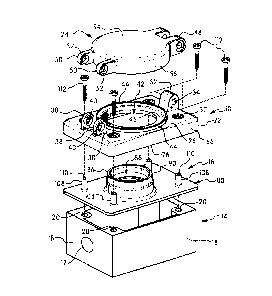
  • HUBBELL INCORPORATED
(71) Applicants :
  • HUBBELL INCORPORATED (United States of America)
(74) Agent: FINLAYSON & SINGLEHURST
(74) Associate agent:
(45) Issued: 2017-02-14
(22) Filed Date: 2009-03-12
(41) Open to Public Inspection: 2009-10-11
Examination requested: 2014-03-04
Availability of licence: N/A
Dedicated to the Public: N/A
(25) Language of filing: English

Patent Cooperation Treaty (PCT): No

(30) Application Priority Data:
Application No. Country/Territory Date
12/081,237 (United States of America) 2008-04-11

Abstracts

English Abstract

An electrical box assembly includes a cover assembly, a gasket and an electrical box coupled together by mounting screws. The cover includes a base with a plurality of screw holes for receiving the mounting screws. A support member having an axial passage extends from the bottom face of the cover around each of the screw holes. The gasket includes a cylindrical shaped sleeve that passes through the support member and has an axial length to extend from the screw hole in the cover. The mounting screws are inserted through the axial passage of the sleeve and the screw holes in the cover to axially compress the sleeve to form a watertight seal between the screw shaft and the support member.


French Abstract

Un ensemble boîtier électrique comporte un ensemble couvercle, un joint détanchéité statique et un boîtier électrique couplés ensemble par des vis de montage. Le couvercle comprend une base avec une pluralité de trous de vis pour recevoir les vis de montage. Un élément de support comportant un passage axial sétend à partir de la face inférieure du couvercle autour de chacun des trous de vis. Le joint détanchéité statique est pourvu dun manchon de forme cylindrique qui passe à travers lélément de support et dont la longueur axiale lui permet de sétendre depuis les trous de vis dans le couvercle. Les vis de montage sont insérées à travers le passage axial du manchon et les trous de vis dans le couvercle pour comprimer axialement le manchon afin de former un joint étanche à leau entre la tige de vis et lélément de support.

Claims

Note: Claims are shown in the official language in which they were submitted.

- 13 -
WHAT IS CLAIMED IS:
1. A cover for an electrical device, said cover comprising:
a base having an opening with a dimension corresponding to the
electrical device, a front surface and a rear surface, a screw hole
extending between said front surface and said rear surface, and a
support member extending from said rear surface; and
a gasket having a body portion corresponding to a dimension of
said base for forming a seal between said base and an electrical box,
said gasket having a front surface, a rear surface, and a sleeve
extending from said front face and positioned to align with said screw
hole and support member of said base, said sleeve having a length to
extending through said base, wherein said sleeve is axially
compressible by a screw extending through said screw hole.
2. The cover of claim 1, wherein said support member has a
cylindrical shape with an axial passage aligned with said screw hole,
said axial passage having an inner dimension complementing an outer
dimension of said sleeve.
3. The cover of claim 2, wherein said front surface of said
base has a substantially flat surface surrounding said screw hole and
where said screw hole has an axis extending substantially
perpendicular to said flat surface.
4. The cover of claim 1, wherein said body portion of said
gasket has a planar configuration, and a collar extending from said
top surface and defining an axial passage through said gasket, said
collar having an axial length sufficient to extend through said opening
in said base.

- 14 -
5. The cover of claim 4, wherein said base includes a closure
member hinged to said base for closing said opening and where said
base includes a rib surrounding said opening in said base for mating
with said closure member.
6. The cover of claim 1, wherein said base has a flange
depending from a perimeter of said base and extending perpendicular
to a plane of said base, and where said support member is a
cylindrical shaped member having an axial length substantially equal
to a length of said flange, whereby said flange and support member
contact said body portion of said gasket.
7. The cover of claim 3, wherein said flat surface of said base
surrounding said screw hole is recessed with respect to said front
surface of said base.
8. A cover for an electrical device, said cover comprising:
a base having an opening with a dimension corresponding to a
dimension of the electrical device, a front surface, and a rear surface,
at least one screw hole extending between said front surface and said
rear surface, and a support member extending from said rear surface
and aligned with said screw hole, said support member having an
axial passage;
a screw having a head and a threaded shaft extending through
said screw hole and support member in said base for coupling said
base to an electrical box; and
a gasket having a bottom portion corresponding to a dimension
of said base for forming a seal between said base and an electrical

- 15 -
box, said gasket having a front surface and a rear surface, a sleeve
extending from said front surface and aligned with said screw hole
and positioned within said support member of said base,
said sleeve having an axial length extending through said screw hole a
distance to contact said screw head, wherein tightening said screw
with respect to said electrical box axially compresses said sleeve to
form a seal against the screw head and to deflect the sleeve radially
outwardly to form a seal between the screw shaft and the support
member.
9. The cover of claim 8, wherein said base comprises a
plurality of said screw holes, each screw hole having a support
member aligned with a respective screw hole, and where said gasket
has a plurality of said sleeves aligned with a respective screw hole,
and where said sleeves have an axial length greater than an axial
length of said support members.
10. The cover of claim 9, wherein said front surface of said
base has a substantially flat surface surrounding said screw holes,
and where said sleeves have an axial length to extend above said flat
surface.
11. The cover of claim 10, wherein said flat surface of each
screw hole is recessed with respect to said front surface of said base.
12. The cover of claim 8, wherein said gasket includes a collar
extending from said top surface of said body portion and defining an
axial passage for the electrical device, said collar having an axial
length sufficient to extend through said opening in said base.

- 16 -
13. The cover of claim 8, wherein said base includes a closure
member hinged thereto to cover said opening and where said base
includes a rib surrounding said opening in said base for mating with
said closure member.
14. The cover of claim 8, wherein said base has a flange
depending from a perimeter thereof and extending perpendicular to a
plane thereof, and where said support members have an axial length
substantially equal to a length of said flange, whereby said flange and
support member contact said body portion of said gasket.
15. The cover of claim 14, wherein said sleeve of said gasket
has an axial length greater than an axial length of said support
member and extends from said screw hole.
16. A method of forming a weatherproof seal between an
electrical box and a cover, said method comprising:
positioning a cover and gasket onto an electrical box,
said cover including a base having an opening with a dimension
corresponding to a dimension of an electrical device mounted to said
electrical box, a front surface and a rear surface, at least one screw
hole extending between said front and rear surface, and a support
member having an axial passage and extending from said rear surface
and aligned with said screw hole;
said gasket having a bottom portion corresponding to a
dimension of said base and an electrical box, a front surface and a
rear surface, and a sleeve extending from said front surface and

- 17 -
extending through said axial passage of said sleeve and through said
screw hole;
inserting a screw through said screw hole and sleeve, threading
into said electrical box, and tightening said screw to axially compress
said sleeve into said screw hole thereby radially expanding said sleeve
to form a seal with said support member and said screw.
17. The method of claim 16, wherein said base has a flange
extending from a perimeter of said base, said support member having
an axial length substantially equal to an axial length of said flange,
wherein said flange and support member contact said front surface
body portion of said gasket.
18. The method of claim 17, wherein said sleeve has an axial
length greater than an axial length of said support member.
19. The method of claim 17, wherein said front surface of said
base has a substantially flat surface portion surrounding said screw
hole and being perpendicular to an axis of said screw hole.
20. The method of claim 19, wherein said flat portion is
recessed from said front surface.
21. The method of claim 19, wherein said screw has a screw
head with a flat axial face, said method comprising tightening said
screw whereby said flat axial face engages an axial end of said sleeve
and axially compress said sleeve.

-18-
22. The method of claim 16, wherein said base includes a
plurality of screw holes and support members and said gasket
includes a plurality of sleeves aligned with a respective screw hole,
said method comprising inserting a screw through each screw holes
and sleeve and coupling to the electrical box to axially compress said
sleeve.
23. The method of claim 22, wherein said support members
have a cylindrical shape and an axial face for contacting said front
surface of said gasket.

Description

Note: Descriptions are shown in the official language in which they were submitted.


CA 02658269 2009-03-12
,
LIFT COVER AND GASKET ASSEMBLY
Field of the Invention
[0001] The present invention is directed to a weatherproof electrical
enclosure and to a weatherproof electrical box assembly. More
particularly, the invention is directed to a weatherproof cover and
gasket assembly for a wiring device.
Background of the Invention
[0002] Various outdoor weatherproof electrical boxes and covers for
electrical wiring devices are known in the art. The weatherproof
covers generally have a cover that is closed by gravity or by a spring
mechanism to close the cover and protect the wiring device from the
weather. The covers are constructed to prevent dirt and water from
entering the electrical box and the electrical device when the cover is
closed.
[0003] Numerous electrical connector housings with hinged lids are
known in the art. One example is disclosed in U.S. Patent No.

CA 02658269 2009-03-12
- 2 -
5,571,023 to Anthony. This patent discloses an electrical connector
lid having a weather tight seal. The weather tight seal is formed in the
lid and seals against a flange formed on the face of the connector
housing.
[0004] Another weatherproof electrical closure is disclosed in U.S.
Patent Publication No. 2006/0037773 to Castaldo et al. The
weatherproof junction box includes a recessed port with a knockout
plug located at an end of the recessed port for connecting an electrical
conduit. The enclosure includes a hinged cover connected to a
stationary portion by a hinge. A rubber gasket is positioned between
the cover and the electrical box to form a weatherproof seal between
the box and the cover. The gasket has a raised portion that extends
through an opening in the stationary portion to form the seal with the
cover.
[0005] U.S. Patent No. 7,192,302 to Phung et al. discloses an
integrated sealable plate assembly. The assembly includes an outer
plate with an opening for a cable connector and screw hole for
receiving a screw. The screw hole has a flared inner surface which
mates with a gasket member. The gasket has a depending portion
with an annular recess that receives the flared portion of the plate.
[0006] While numerous devices have been made to provide a cover
for an opening of electrical connectors, the prior devices have various
disadvantages. Many of these prior devices require many parts and
are expensive to manufacture. In addition, many of the prior devices
do not provide adequate sealing to prevent water and/or dirt from
entering the cover.
[0007] Accordingly, there is a continuing need in the industry for an
improved cover assembly for an electrical box.

CA 02658269 2009-03-12
- 3 -
Summary of the Invention
[0008] The present invention is directed to an electrical box
assembly having a cover, a gasket and an electrical box. The
invention is particularly directed to an electrical box assembly for
providing a watertight seal to protect the electrical device mounted
within the electrical box from water and debris.
[0009] Accordingly, one aspect of the invention is to provide an
electrical connector housing, such as an electrical box, and having a
cover member on the housing that provides a watertight seal between
the housing and the cover.
[0010] Another aspect of the invention is to provide an electrical
connector housing having a gasket that forms a watertight seal
between the base of the cover and the electrical box. The gasket has a
dimension to form a watertight seal between the perimeter of the cover
and the electrical box. The gasket also forms a watertight seal
between the mounting screws and the cover when the cover is
attached to the electrical box and between a hinged closure member
on the cover and the base of the cover.
[0011] A further aspect of the invention is to provide a gasket having
a collar extending from the plane of the gasket and forming a
watertight seal between the base of the cover and the electrical box.
The base of the cover has a gasket support member with an axial
passage extending from the bottom side and aligned with the screw
holes. In one embodiment the support member has a cylindrical
shape extending from the base. The gasket includes a sleeve with an
axial passage that is inserted into the axial passage of the support
members. The mounting screws are passed through the axial passage
of the sleeve and support member to axially compress the sleeve,

CA 02658269 2009-03-12
- 4 -
thereby radially deforming a portion of the sleeve and forming a seal
between the screw shaft and the support member of the base.
[0012] The foregoing aspects of the invention are basically attained
by providing a cover for an electrical device comprising a base having
an opening with a dimension corresponding to the electrical device, a
front surface and a rear surface. A screw hole extends between the
front surface and the rear surface, and a support member extends
from the rear surface. A gasket with a body portion corresponds to a
dimension of the base for forming a seal between the base and an
electrical box. The gasket has a front surface, a rear surface, and a
sleeve extending from the front face and is positioned to align with the
screw hole and the support member of the base. The sleeve has a
length to extend through the base. The sleeve is axially compressible
by a screw extending through the screw hole.
[0013] The aspects of the invention are also attained by providing a
cover for an electrical device which comprises a base having an
opening with a dimension corresponding to a dimension of the
electrical device, a front surface, and a rear surface. At least one
screw hole extends between the front surface and the rear surface,
and a support member having an axial passage extends from the rear
surface and is aligned with the screw hole. A screw has a head and a
threaded shaft that extends through the screw hole and support
member in the base for coupling the base to an electrical box. A
gasket has a bottom portion corresponding to a dimension of the base
for forming a seal between the base and an electrical box. The gasket
has a front surface and a rear surface and a sleeve extending from the
front surface and aligned with the screw hole and positioned within
the cylindrical support member of the base. The sleeve has an axial
length extending through the screw hole a distance to contact the

CA 02658269 2009-03-12
- 5 -
screw head. Tightening the screw with respect to the electrical box
axially compresses the sleeve to form a seal against the screw head
and to deflect a portion of the sleeve radially outwardly to form a seal
between the screw shaft and the support member.
[0014] The various aspects of the invention are also attained by
providing a method of forming a weatherproof seal between an
electrical box and a cover. The method comprises positioning a cover
and gasket onto an electrical box. The cover includes a base having
an opening with a dimension corresponding to a dimension of an
electrical device mounted to the electrical box, a front surface and a
rear surface. At least one screw hole extends between the front and
rear surface, and a support member has an axial passage and extends
from the rear surface and is aligned with the screw hole. The gasket
has a bottom portion corresponding to a dimension of the base and an
electrical box, a front surface and a rear surface. A sleeve extends
from the front surface through the axial passage of the sleeve and
through the screw hole. A screw is inserted through the screw hole
and sleeve and threads into the electrical box. The screw is tightened
to axially compress the sleeve into the screw hole, thereby radially
expanding the sleeve to form a seal with the support member and the
screw.
[0015] Other aspects, advantages and salient features of the
invention will become apparent to those skilled in the art from the
following detailed description, which taken in conjunction with the
annexed drawings, discloses various embodiments of the present
invention.

CA 02658269 2009-03-12
- 6 -
Brief Description of the Drawings
[0016] Referring to the drawings which form a part of this original
disclosure, in which:
[0017] Figure 1 is a perspective view of the electrical box assembly
in one embodiment of the invention;
[0018] Figure 2 is a side view of the electrical box assembly of
Figure 1;
[0019] Figure 3 is a top view of the electrical box assembly of Figure
1;
[0020] Figure 4 is a top plan view of the base of the cover without
the closure member in one embodiment of the invention;
[0021] Figure 5 is an exploded perspective view of the electrical box
assembly of Figure 1;
[0022] Figure 6 is an exploded cross-sectional view taken along line
6-6 of Figure 4;
[0023] Figure 7 is a perspective bottom view showing the gasket and
base of the cover;
[0024] Figure 8 is an enlarged partial perspective view of the
support member extending from the base of the cover;
[0025] Figure 9 is an enlarged partial view showing the gasket
assembled to the base with the gasket sleeve extending through the
support member; and
[0026] Figure 10 is an enlarged partial view showing the sleeve of
the gasket being axially compressed and radially deformed.
Detailed Description of the Invention
[0027] The present invention is directed to a waterproof electrical
box assembly. In particular, the invention is directed to an electrical

CA 02658269 2009-03-12
- 7 -
box assembly that includes a waterproof seal to protect the electrical
components from water and debris.
[0028] Referring to the drawings, the electrical box assembly 10 of
the invention includes a cover 12, electrical box 14 and a gasket 16.
[0029] Electrical box 14 is a standard enclosure for supporting
electrical wiring and an electrical device such as a switch or electrical
receptacle. In the embodiment illustrated, electrical box 14 is a
weatherproof electrical box designed for outdoor use or for use in wet
environments. One or more knockouts 17 can be provided in the side
walls 18 to feed electrical wiring to the electrical device. For
simplicity, the electrical device is not shown in the drawings.
Electrical box 14 includes a plurality of threaded screw holes 20 for
coupling cover 12 to electrical box 14 as shown in Figure 5.
[0030] Cover 12 includes a base 22 and a closure member 24
forming a lid. Base 22 includes a front surface 26 and a rear surface
28 and a plurality of screw holes 30 extending between the front
surface 26 as shown in Figure 4 and rear surface 28 as shown in
Figure 7.
[0031] Referring to Figures 1 and 5, base 22 includes a hinge
member 32 having a hinge hole 34 for receiving hinge pin 36. In the
embodiment illustrated, hinge member 32 is positioned at one end of
base 22. The opposite end of base 22 is provided with a pair of
locking members 38 having a hole 40 for receiving the shank of a pad
lock (not shown). Cover 12 is preferably made from a rigid material
such as metal or a rigid plastic material.
[0032] Base 22 in the embodiment illustrated has a generally
rectangular shape and has a shape and dimension corresponding to
the open top end of electrical box 14. Base 22 includes a central
opening 42 for accessing the electrical device mounted in electrical

CA 02658269 2009-03-12
- 8 -
box 14 and for receiving gasket 16. Opening 42 has a shape
corresponding to the shape and dimension of the electrical device. In
the embodiment shown in Figure 5, opening 42 has a circular shape
centrally located on the front surface 26 of base 22. In this
embodiment, the electrical device can be, for example, an electrical
receptacle. An annular rib 44 encircles opening 42 and is spaced
from opening 42 to define a ledge 46. Annular rib 44 extends in a
direction substantially perpendicular to the plane of front surface 26
of base 22.
[0033] Closure member 24 defines a lid for closing the opening 42 in
base 22 and covering the electrical device mounted in the electrical
box 14. Closure member 24 includes a pair of hinge members 48 for
mating with hinge member 32 of base 22. Hinge member 48 is
coupled to hinge member 32 by hinge pin 36 to pivotally connect
closure member 24 to base 22. Closure member 24 also includes a
pair of locking members 50 having a hole 52 for aligning with the hole
40 of locking members 38 of base 22. The shank of a padlock (not
shown) can be passed through the holes in the locking members to
prevent unauthorized access to the electrical device.
[0034] Closure member 24 has a shape and dimension
complementing the shape and dimension of opening 42 and annular
rib 44 of base 22. In one embodiment, cover member 24 includes a
top wall 54 and a side wall 56. Side wall 56 in the embodiment
illustrated has a shape complementing the shape and dimension of
annular rib 44. Side wall 56 preferably mates with rib 44 to prevent
or inhibit debris and water from entering closure member 24. Closure
member 24 can be spring biased to a closed position. Closure
member 24 preferably includes an annular inner wall 58 shown in
Figure 6 for mating with gasket 16. Inner wall 58 is concentric with

CA 02658269 2009-03-12
- 9 -
side wall 56 and has a dimension to mate with the opening 42 in base
22 and gasket 16 and to cover the electrical device in the electrical box
14.
[0035] Screw holes 30 in base 22 in one embodiment of the
invention are recessed with respect to front surface 26 as shown in
Figures 6 and 9. Recess 60 surrounds the screw hole 30 and includes
a bottom portion 62 and a side portion 64. Bottom portion 62 has a
substantially flat planar surface perpendicular to the axis of screw
hole 30 and parallel to front surface 26. Side portion 64 has a
generally curved shape extending from flat bottom portion 62 to front
surface 26.
[0036] As shown in Figure 7, base 22 has a flange 66 extending
from the perimeter of base 22 and perpendicular to the plane of front
surface 26. Preferably, flange 66 is continuous and integrally formed
with base 22. As shown in Figures 7 and 8, a plurality of support
members 68 extends from the rear surface 28 of base 22. The support
members 68 have an axial passage 70 aligned with a respective screw
hole 30 so that the support members 68 surround the respective
screw hole 30. In the embodiment illustrated, the support members
68 are cylindrical shaped members integrally formed with base 22 and
have an axial end 72. Preferably, support member 68 has a
chamfered inner edge 74 at the axial end 72. Axial end 72 typically
has a flat surface perpendicular to the axis of the axial passage 70. In
the embodiment shown, support member 68 defines a continuous
cylindrical annular member. In alternative embodiments, support
member 68 can have one or more longitudinal slots, can be formed
from a plurality of members arranged to encircle the screw hole, or
have a non-circular configuration such as a square, rectangle or other
shape that is capable of supporting the cover and forming a seal with

CA 02658269 2009-03-12
- 10 -
the gasket as discussed hereinafter. Support member 68 has an axial
length substantially equal to an axial length of flange 66. Preferably,
flange 66 has a bottom edge 76 lying in the same plane as axial end
72 of support member 68.
[0037] A gasket 16 is positioned between base 22 and electrical box
14 to form a watertight seal to prevent water and debris from entering
the electrical box 14 and from entering between cover 12 and gasket
16. Gasket 16 has a planar base portion 80 having a dimension
complementing the top end of electrical box 14 and complementing
the dimension of flange 66 of base 22. Base portion 80 has a
substantially planar top surface and a planar bottom surface with a
thickness sufficient to form a watertight seal. Preferably, gasket 16 is
made from an elastomeric material that is sufficiently flexible to form
a watertight seal.
[0038] Gasket 16 has an annular collar 86 defining an axial passage
88. As shown in Figure 6, collar 86 has a generally cylindrical shape
with an axial length to extend through opening 42 in base 22.
Preferably, collar 86 forms a waterproof seal between collar 86 and the
inner edge of opening 42. Water that does enter through opening 42
is prevented from entering electrical box 14 by the bottom portion 80
of gasket 16. Collar 86 has an axial end 90 with a chamfered outer
surface 92 and a chamfered inner surface 94. Collar 86 includes an
annular recess having an annular rib 98 and forming a lip 100 with
the inner chamfered edge 94. Collar 86 is formed with a chamfered
bottom edge 102 adjacent bottom surface 84. An annular inner
surface 104 is formed between recess 96 and chamfered bottom edge
102 for forming a seal with the electrical device. In the embodiment
shown in the drawings, collar 86 is a cylindrical annular shaped
member to accommodate the opening in base 22 and the electrical

CA 02658269 2015-11-24
- 11 -
device. In other embodiments, collar 86 can have a shape
corresponding to the shape of the opening in base 22 to form a
watertight seal.
[0039] Base portion 80 of gasket 16 includes a plurality of screw
holes 106 aligned with the screw holes in base 22. A cylindrical
shaped sleeve 108 having an axial passage 110 extends from top
surface 82 encircling the screw holes 86. Sleeve 108 is integrally
formed with gasket 16 and is sufficiently flexible to form a watertight
seal between sleeve 108 and base 22. In the embodiment shown
sleeve 108 has a substantially cylindrical shape to complement the
shape of the corresponding support member 68. Preferably, sleeve
108 has an outer shape and dimension corresponding to the shape
and dimension of the axial passage of sleeve 68. Sleeve 108 has an
outer dimension to fit within the axial passage 70 of the respective
support member 68 and an inner dimension to receive a mounting
screw. As shown in Figure 6, sleeve 108 has an axial length slightly
greater than the axial length of support member 68 and a length to
extend into the recess 60. In the embodiment shown in Figure 9,
sleeve 108 has an axial length to extend above flat bottom portion 62
of recess 60 and below the front surface 26 of base 22 such that the
axial end of sleeve 108 is positioned within the recess 60.
[0040] Cover 12 is attached to electrical box 14 with gasket 16
positioned therebetween. A plurality of threaded screws 112 having a
head 114 and a threaded shaft 116 extend through screw holes 30 in
base 22 and the axial passage 110 of sleeve 108 and into the threaded
holes 20 of electrical box 14. Gasket 16 is assembled onto cover 12 as
shown in Figure 6 by inserting the sleeves 108 through a respective
axial passage of the support member 68 and by inserting collar 86
through opening 42 in base 22. As shown in Figure 9, screw head

= CA 02658269 2015-11-24
- 12 -
114 has a substantially flat axial face 118 substantially perpendicular
to the axis of threaded shaft 116. The top face of screw head 114
includes a slot 120 for engaging a screwdriver. Screw 112 passes
through the axial passage of sleeve 108 until the axial bottom face 118
of screw head 114 contacts the flat axial face 122 of sleeve 108.
Screws 112 are tightened to axially compress sleeve 108 into the
respective support member 68 and to compress the axial end of sleeve
108 into the screw hole 30 and axial passage 110 of sleeve 108. The
axial compression of sleeve 108 causes at least a portion of the sleeve
108 to expand radially into contact with the screw shaft 116 and the
inner surface of support member 68 to form a watertight seal between
screw 112 and support member 68. Typically the axial compression
causes the sleeve 108 to buckle slightly so that a middle portion of the
sleeve expands radially. Preferably, the top end of sleeve 108 is axially
compressed into the screw hole 30 of base 22 without flaring the top
end outwardly or contacting the surfaces of the recess 60. The axial
face 118 of screw head 114 directly contacts the flat bottom surface
62 of recess 60 as shown in Figure 10. The axial compression and
radial expansion of sleeve 108 forms a watertight seal to prevent water
and debris from entering the electrical box through the screw hole. In
one embodiment screw head 114 has an inclined surface between the
flat axial face 118 and shaft 116. Preferably the inclined surface does
not cause any substantial flaring of the axial end of the sleeve so that
the sleeve will compress axially.
[0041] While various embodiments have been illustrated and
described, it will be understood by one skilled in the art that various
changes and modifications can be made without departing from the
scope of the invention as defined in the appended claims:

Representative Drawing
A single figure which represents the drawing illustrating the invention.
Administrative Status

2024-08-01:As part of the Next Generation Patents (NGP) transition, the Canadian Patents Database (CPD) now contains a more detailed Event History, which replicates the Event Log of our new back-office solution.

Please note that "Inactive:" events refers to events no longer in use in our new back-office solution.

For a clearer understanding of the status of the application/patent presented on this page, the site Disclaimer , as well as the definitions for Patent , Event History , Maintenance Fee  and Payment History  should be consulted.

Event History

Description Date
Common Representative Appointed 2019-10-30
Grant by Issuance 2017-02-14
Inactive: Cover page published 2017-02-13
Inactive: Final fee received 2016-12-22
Pre-grant 2016-12-22
Notice of Allowance is Issued 2016-06-23
Letter Sent 2016-06-23
Notice of Allowance is Issued 2016-06-23
Inactive: Approved for allowance (AFA) 2016-06-17
Inactive: Q2 passed 2016-06-17
Amendment Received - Voluntary Amendment 2015-11-24
Inactive: S.30(2) Rules - Examiner requisition 2015-06-08
Inactive: Report - No QC 2015-06-02
Letter Sent 2014-03-11
Request for Examination Requirements Determined Compliant 2014-03-04
All Requirements for Examination Determined Compliant 2014-03-04
Request for Examination Received 2014-03-04
Application Published (Open to Public Inspection) 2009-10-11
Inactive: Cover page published 2009-10-11
Inactive: IPC assigned 2009-09-14
Inactive: First IPC assigned 2009-09-14
Inactive: IPC assigned 2009-09-14
Inactive: Office letter 2009-04-14
Inactive: Filing certificate - No RFE (English) 2009-04-08
Filing Requirements Determined Compliant 2009-04-08
Letter Sent 2009-04-08
Application Received - Regular National 2009-04-08

Abandonment History

There is no abandonment history.

Maintenance Fee

The last payment was received on 2016-03-03

Note : If the full payment has not been received on or before the date indicated, a further fee may be required which may be one of the following

  • the reinstatement fee;
  • the late payment fee; or
  • additional fee to reverse deemed expiry.

Please refer to the CIPO Patent Fees web page to see all current fee amounts.

Owners on Record

Note: Records showing the ownership history in alphabetical order.

Current Owners on Record
HUBBELL INCORPORATED
Past Owners on Record
THOMAS J. VIGORITO
THOMAS W. BRACCI
Past Owners that do not appear in the "Owners on Record" listing will appear in other documentation within the application.
Documents

To view selected files, please enter reCAPTCHA code :


To view images, click a link in the Document Description column. To download the documents, select one or more checkboxes in the first column and then click the "Download Selected in PDF format (Zip Archive)" or the "Download Selected as Single PDF" button.

List of published and non-published patent-specific documents on the CPD .

If you have any difficulty accessing content, you can call the Client Service Centre at 1-866-997-1936 or send them an e-mail at CIPO Client Service Centre.


Document
Description 
Date
(yyyy-mm-dd) 
Number of pages   Size of Image (KB) 
Abstract 2009-03-12 1 19
Description 2009-03-12 12 495
Claims 2009-03-12 6 190
Drawings 2009-03-12 4 140
Representative drawing 2009-09-17 1 14
Cover Page 2009-10-01 1 44
Description 2015-11-24 12 494
Claims 2015-11-24 6 189
Representative drawing 2016-06-02 1 16
Cover Page 2017-01-12 2 49
Representative drawing 2017-01-12 1 14
Courtesy - Certificate of registration (related document(s)) 2009-04-08 1 102
Filing Certificate (English) 2009-04-08 1 156
Reminder of maintenance fee due 2010-11-15 1 113
Reminder - Request for Examination 2013-11-13 1 117
Acknowledgement of Request for Examination 2014-03-11 1 176
Commissioner's Notice - Application Found Allowable 2016-06-23 1 163
Correspondence 2009-04-08 1 13
Amendment / response to report 2015-11-24 11 373
Final fee 2016-12-22 1 28