Note: Descriptions are shown in the official language in which they were submitted.
- I CA 02658724 2009-01-22
WO 2008/014858 PCT/EP2007/005856
1
METHOD FOR PRODUCTION OF A PLURALITY OF FIBER-COMPOSITE
STRUCTURAL ELEMENTS
The present invention relates to a method for production of fiber-composite
structural
elements.
The use of fiber-composite structural elements is interesting for many areas
of
application, in particular because of their high specific strength (ratio of
strength to
weight). A fiber-composite material is a mixed material that is generally
composed of
two main components, namely a matrix and fibers embedded therein. Mutual
interactions of these components endow the material with higher-performance
characteristics than those of the two individual components involved.
In particular, the present invention relates to the production of highly
stressed profile
sections having more or less complicated geometry. According to prior art
based on
internal industrial know-how of the Applicant, carbon-fiber-reinforced plastic
profile
sections, for example, are mostly produced at present either in prepreg
technology or
by draping semifinished textile products (woven and nonwoven fabrics, fiber
mats, etc.)
of carbon fibers. However, this requires a relatively large amount of manual
labor. In the
production of curved profile sections, the cutting loss is typically as high
as 50%.
The only manufacturing process known to date to be more streamlined with a
small
percentage of waste for the production of carbon-fiber-reinforced plastic
profile sections
is pultrusion. However, only straight profile sections with constant cross
section can be
manufactured with this process. Local thick zones, partly optimized fiber
angle or even
modifications of the shape are not possible. For practical purposes,
therefore, such
structural elements often have to be provided with thick zones (for stiffening
and/or
subsequent force transmission) by laborious post-processing.
, CA 02658724 2009-01-22
WO 2008/014858 PCT/EP2007/005856
2
It is therefore an object of the present invention to provide a simple method
for the
production of fiber-composite structural elements, which method is also
suitable in
particular for the production of fiber-composite structural elements having
complex
geometry, such as profile sections with varying profile cross section and/or
with curved
shape in at least some portions.
This object is achieved according to the invention by a method for production
of fiber-
composite structural elements comprising the steps of:
a) providing a plurality of core parts,
b) separately applying a first fiber material on each of the core parts,
c) joining the core parts lined with the first fiber material to one another
to form a
core-part row,
d) applying a second fiber material common to the core-part row along at least
one side of the core-part row on which the core parts are lined with the first
fiber material,
e) infiltrating and curing the first and second fiber materials to form a
fiber-
reinforced structural-element block, and
f) subdividing the structural-element block into a plurality of portions,
which
represent the fiber-composite structural elements.
With this method it is possible in simple manner to produce even fiber-
composite
structural elements of complex shape, especially, for example, even elongated
curved
CA 02658724 2009-01-22
WO 2008/014858 PCT/EP2007/005856
3
profiled structural elements with irregular radius of curvature. A particular
advantage of
the invention is that a plurality of fiber-composite structural elements,
especially a
plurality of identical fiber-composite structural elements, can be produced
simultaneously and therefore inexpensively with the method ("package
manufacture").
In this respect, the simultaneous production of at least three, especially at
least five or
even at least ten structural elements is preferred.
In principle, the inventive method is not subject to any special restrictions
on the type of
fiber material to be used (such as individual fibers, rovings, flat
semifinished fiber
products, etc.) or on the type of matrix material to be used. In one
embodiment, the use
of carbon fibers is provided. Alternatively or additionally, however, it is
possible without
difficulty to use even other fibers, such as glass fibers, synthetic plastic
fibers, steel
fibers or natural fibers. Interesting in particular as matrix materials are
plastics, such as
thermosetting plastics (synthetic resins). However, the items in these lists
are to be
understood only as examples. Moreover, fillers or additives may be
incorporated in
ways known in themselves if necessary.
The terms "first fiber material" and "second fiber material" used here are
intended to
convey the fact that fiber material is used in two stages in the inventive
method, namely
first in step b), in which a fiber material is applied separately on each of
the core parts,
and later in step d), in which a fiber material is applied on the previously
formed core-
part row. These terms are not intended to give the impression that the first
fiber material
must be different from the second fiber material. This can indeed be provided,
but is by
no means imperative. In this sense, it is also possible to use a plurality of
different first
fiber materials in step b) and/or a plurality of different second fiber
materials in step d).
The term "application" (of the fiber material in question) is to be understood
very broadly
within the scope of the invention. As an example, individual fibers can be
applied by a
circular braiding or wrapping process. Alternatively or additionally,
application may also
I CA 02658724 2009-01-22
WO 2008/014858 . PCT/EP2007/005856
4
take place by laying (especially in the case of a flat semifinished textile
product), fixed if
necessary by an adhesive layer.
In a preferred embodiment, the core parts are formed as profiled parts, whose
profile
cross section varies over the longitudinal extent of the profile and/or whose
longitudinal
extent of the profile has curved shape in at least portions. Since the core
parts being
used define the shape for the manufactured structural elements, it is
therefore possible
to produce, with this measure, profiled structural elements wherein the
profile cross
section varies over the longitudinal extent of the profile and/or wherein the
longitudinal
extent of the profile has curved shape (including "kinked" shape) in at least
portions. In
a preferred embodiment, the produced profiled structural elements are
elongated, and
in particular the longitudinal extent of the profile is larger by a factor of
at least 5,
especially by a factor of at least 10 than the maximum longitudinal extent of
the profile.
To produce a plurality of elongated profiled structural elements, it is
possible to provide,
in step a) for example, a plurality of identical elongated profiled core
parts, which, after
application of the fiber material in step b), are joined to one another along
their
longitudinal sides to form a core-part row, before the fiber material common
to the core-
part row is applied in step d), for example by being laid. The core-part row
then has a
length that corresponds to the length of the individual profiled core parts
and a width
that corresponds to the sum of the widths of the individual profiled core
parts plus the
thicknesses of the fiber material in the direction in which the core parts are
joined to
one another or arranged in a row.
The core parts used in the method can be provided as reusable or non-reusable
parts.
In the case of reusable core parts, which may be made of metal (such as
aluminum),
for example, it is merely necessary to ensure that these are not damaged while
the
structural-element block is being subdivided in step f), if at that time the
core parts are
still located inside the structural-element block. Non-reusable core parts can
be formed
+ CA 02658724 2009-01-22
WO 2008/014858 PCT/EP2007/005856
in simple manner, for example from plastic, especially foamed plastic, and can
be cut
apart from one another and therefore destroyed if necessary during subdivision
of the
structural-element block.
In one embodiment it is provided that the core parts have at least one local
recess,
which is filled with fiber material in step b). In this way local thick zones
for the finished
structural element can be created in simple manner. An alternative or
additional
possibility is to form such local thick zones by laying the first fiber
material in step b)
and/or the second fiber material in step d) in a thickness that is greater at
one or more
locations.
If necessary, local thick zones can be formed by a special material, such as
fiber
material, which may be different from the first fiber material and/or the
second fiber
material. If the core part is provided with one or more of the aforesaid local
recesses for
this purpose, it is possible, for example, to lay one or more cut-to-size
pieces of a
semifinished textile product in each of these recesses (integration of
reinforcing plies).
In a more special embodiment, it is provided that a local recess at the
surface of the
core part in question is filled to level condition and subsequently completely
covered
during application of the first fiber material.
In a preferred embodiment it is provided that the application of the first
fiber material in
step b) comprises circular braiding and/or wrapping of the individual core
parts. This
method of applying the first fiber material can be automated very readily, for
example
by using a method or an apparatus such as described in German Unexamined
Patent
Application DE 102004017311 Al (for the production of semifinished fiber-
composite
products). Accordingly, the application of the first fiber material in step b)
can be
accomplished in particular by means of circular braiding techniques, wherein
the core
part in question is braided with braiding threads wound over lace bobbins
revolving
concentrically in different directions around the core part. In this case it
can be provided
' CA 02658724 2009-01-22
WO 2008/014858 PCT/EP2007/005856
6
in particular that the lace bobbins of one direction of revolution are filled
with reinforcing
threads and the lace bobbins of the opposite direction of revolution are
filled at least
partly with support threads, which are able to hold the reinforcing threads in
position
and which can consist at least partly of thermoplastic threads. In a preferred
improvement, the core part is braided several times, in each case by laying
unidirectional individual plies of the first fiber material onto the core
part. By virtue of
automated application of the first fiber material by a circular braiding
technique, it is
advantageously possible to achieve high reproducibility and well-defined fiber
orientation (unidirectional or multidirectional). Moreover, additional strips
of fiber
material can be interposed in simple manner during the circular braiding
process. In a
preferred embodiment of circular braiding, an even braid, or in other words a
non-wavy
braid, is formed.
The local thick zones explained in the foregoing can be formed directly during
circular
braiding and/or wrapping as early as step b), or else they can be formed by
locally
repeated circular braiding or wrapping processes or even by flat semifinished
fiber-
material products (cut-to-size pieces, strips, etc.) to be additionally
inserted.
In principle, another conceivable alternative to circular braiding or wrapping
in step b) is
in particular draping of fiber-material plies, although this usually involves
considerably
more manual labor in practice. In one embodiment, it is therefore provided
that a large
part of the first fiber material will be laid on the core part in question by
circular braiding
or wrapping, while if need be a smaller proportion of the first fiber material
is laid in the
form of a flat semifinished fiber composite, which if necessary is cut to
size. The latter
application of a ply of fiber material may be accompanied in particular
(before and/or
after) by circular braiding or wrapping.
I CA 02658724 2009-01-22
WO 2008/014858 PCT/EP2007/005856
7
In one embodiment it is provided that the core parts lined and joined together
are fixed
in step c) by means of a holding device, which is part of an infiltration unit
used for step
e). The infiltration unit can in turn be part of a mold, in which both
infiltration of the fiber
material with the matrix material in question and at least partial curing of
the fiber-matrix
composite are performed. Depending on the number of pieces of fiber-composite
structural elements to be produced, either an open mold or a closed mold may
be used
during joining together (stacking) of the lined core parts and/or during
application of the
second fiber material (for example, cover plies of multiaxial nonwoven
fabrics, woven
fabrics, etc. on one or two sides) and/or during infiltration or curing.
In a preferred embodiment it is provided that the application of the second
fiber material
in step d) comprises the application of at least one sheet-like ply of fiber
material (such
as semifinished textile), which may be in particular a cut-to-size piece or
strip of
multiaxial nonwoven fabric, woven fabric or similar material.
The second fiber material may be laid if necessary on both sides of the core-
part row,
using the same or different material type and the same or different material
thickness
(and also in a plurality of layers).
The infiltration and curing provided in step e) can be advantageously achieved
with all
methods known in themselves from fiber-composite manufacturing practice (such
as
VAP, RTM, etc.). In the case of infiltration with an epoxy resin, it is
possible to achieve
curing thermally, for example, in a temperature range from room temperature to
approximately 180 C, depending on the nature of the resin.
In one embodiment it is provided that the structural-element block is
subdivided in step
f) by a plurality of parting cuts that take place respectively in the region
of one of the
core parts, wherein each parting cut causes the fiber material (and possibly
the core
' CA 02658724 2009-01-22
WO 2008/014558 PCT/EP2007/005856
8
part) adjoining the core part in question to be split and thus associated with
several of
the resulting fiber-composite structural elements.
Core parts not scheduled for reuse (such as foamed-material cores) may be
destroyed
if necessary during removal from the mold.
The fiber-composite structural elements formed by subdivision of the
structural-element
block in step f) may be post-machined if necessary before being used.
The invention will be described further hereinafter on the basis of exemplary
embodiments with reference to the attached drawings, wherein:
Fig. 1 shows a diagram for illustration of the production of a plurality of
fiber-reinforced
profile sections, wherein the profile cross section varies over the
longitudinal
extent of the profile,
Fig. 2 shows a diagram for illustration of the production of a plurality of
fiber-reinforced
profile sections, wherein the longitudinal extent of the profile has a curved
shape,
Fig. 3 shows a detail from Fig. 2,
Fig. 4 shows a perspective view of a core part according to a further
embodiment,
Fig. 5 shows a diagram for illustration of examples of the geometries of
several core-
parts or fiber-composite structural elements,
Fig. 6 shows a schematic diagram of the automated application of a fiber
material on a
core part, and
CA 02658724 2009-01-22
WO 2008/014858 PCT/EP2007/005856
9
Fig. 7 shows a schematic diagram of the application of a multiaxial fiber
material on
individual core parts, on the one hand for core parts with rectilinear extent
and
on the other hand for core parts with curved extent.
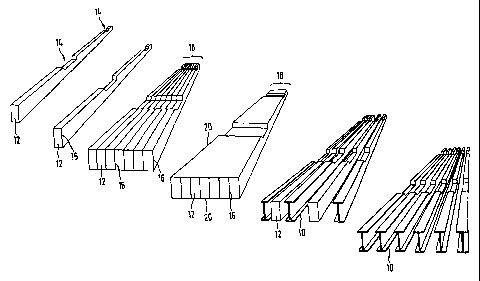
Fig. 1 illustrates, from left to right, various stages during the simultaneous
production of
six fiber-composite structural elements 10 in the form of I-beam sections (see
extreme
right in Fig. 1).
This "package manufacture" of profile sections 10, which will be subsequently
usable as
crossbeams in the floor of an aircraft fuselage, for example, comprises the
following
steps:
a) Firstly there are provided core parts 12 of the type illustrated at the
extreme left in
Fig. 1 (in Fig. 7 there are illustrated seven such core parts, which in the
illustrated
exemplary embodiment are formed as core-part profile sections, which are
elongated in one direction and whose profile cross section varies over the
longitudinal extent of the profile). In the illustrated example the profile
cross section
is rectangular, with visible indentations 14, where the cross-sectional area
is
correspondingly reduced, at two positions along the extent of the profile. As
an
example, core parts 12 can be produced by milling a commercial hard foamed
material or else a metal material. Their nature is of secondary importance,
since
they are used only as shaping aids in the production of the actual structural
elements 10.
b) In the next step, a first fiber material 16 is applied separately on each
of core parts
12. In the illustrated exemplary embodiment, this step comprises circular
braiding of
core parts 12 with the fiber material. In view of the subsequent use of
structural
elements 10, a favorable fiber orientation (or plurality of fiber
orientations) can be
provided in a manner known in itself for this purpose. Such core parts 12 are
used
as "braided cores".
CA 02658724 2009-01-22
WO 2008/014858 - PCT/EP2007/005856
c) Core parts 12 lined with first fiber material 16 are then joined to one
another to form
a core-part row 18. In the illustrated exemplary embodiment, each two
immediately
neighboring core parts 12 enveloped with fiber material 16 (completely, except
for
the end faces) are in contact along a plane boundary face, so that the
individual
lined core parts 12 bear against one another with their entire surface as
viewed in
stacking direction.
d) A second fiber material 20 is then applied along at least one side of core-
part row
18. In the illustrated exemplary embodiment, this fiber material 20 is applied
both
on the bottom side and top side of illustrated core-part row 18.
e) The structure created in this way and comprising shaping core parts 12
lined up
against one another and also fiber materials 16, 20 is then infiltrated with a
suitable
matrix material (such as epoxy resin) and thermally cured. In a preferred
embodiment, the curable matrix material is added by using a vacuum infusion
process, for example by means of a standard infusion process such as VAP,
VARI,
etc. For this purpose it is possible to use, for example, an infiltration
system with
membrane structure, wherein appropriate inlets and outlets for a resin matrix
are
provided in a covering film and/or in a mold. Such a vacuum system may also be
used if necessary for compaction of core-part row 18 lined with fiber
material. When
the lined core-part row is covered with an airtight film and then the space
under the
film is more or less evacuated, the system is subjected to the atmospheric
ambient
pressure. Alternatively or in addition to evacuation of the space bounded by
the
film, an elevated ambient pressure may be applied, for example by introducing
lined
core-part row 18 together with film in an autoclave. Complete curing or even
only
partial curing may be provided in this step.
' CA 02658724 2009-01-22
WO 2008/014858 PCT/EP2007/005856
11
f) Finally, the structural-element block created in the previous step by
infiltration and
curing is subdivided into a plurality of portions, which (after final post-
machining if
necessary) represent fiber-composite structural elements 10. In general,
depending
on the geometry of core parts 12 and the thickness of the binding of fiber
material
at the surface of core parts 12, it will not be possible to remove these core
parts
before the structural-element block is subdivided. In one embodiment, it is
therefore
provided that both fiber material 16, 20 and also core parts 12 will be
severed by
parting cuts (core parts 12 not reusable). In another embodiment, it is
provided that
parting cuts will be made in such a way that only fiber material 16, 20 is
severed
thereby and that core parts 12 released as a result are reusable.
By means of the described production method, six fiber-reinforced I-beams 10
are
produced simultaneously by using seven core parts 12, in the manner
illustrated in Fig.
1. In this case, the structural-element block is subdivided by seven parting
cuts (vertical
in Fig. 1), each passing through the region of one of core parts 12, wherein
each parting
cut causes fiber material 16, 20 adjoining core part 12 in question to be
split and thus
associated with several of the resulting fiber-composite structural elements
10.
In a deviation from the illustrated exemplary embodiment, individual beams 10
could be
endowed in simple manner with an approximate C-shaped profile, by positioning
the
planes of the vertical parting cuts somewhat offset relative to the
illustrated exemplary
embodiment (by approximately half the width of a core part 12).
Starting from the structural-element block illustrated in Fig. 1, it would
also be possible
to produce (twice as many) T-beams or L-beams, for example, by the subdivision
step,
for example by providing a horizontal parting cut in addition to the vertical
parting cuts.
CA 02658724 2009-01-22
WO 2008/014858 PCT/EP2007/005856
12
As an example, the I-beams or C-beams originally obtained by separating the
structural-element block are each split one more time horizontally.
In the exemplary embodiment according to Fig. 1, core parts 12 are each
elongated
and have identical shape, and the longitudinal extent of their profile is
rectilinear (and
orthogonal to the subsequent stacking direction). However, the profile cross
section
varies over the longitudinal extent of the profile (see indentations 14).
Profiled core
parts 12 are arranged with identical orientation in core-part stack 18.
In the description hereinafter of further exemplary embodiments, like
reference
numerals are used for components having like effect, but in each case they are
supplemented by a lower-case letter to distinguish the embodiment. Thus
substantially
only the differences relative to the already described exemplary embodiment or
embodiments will be pointed out and otherwise the description of the preceding
exemplary embodiments will be expressly applicable by reference.
Figs. 2 and 3 illustrate an exemplary embodiment of a method for simultaneous
production of a plurality of fiber-composite structural elements, which are
again formed
as I-beam sections as in the example described hereinabove with reference to
Fig. 1. In
a deviation from the foregoing example, however, the longitudinal extent of
the
produced profiled structural elements has curved shape.
In a diagram similar to Fig. 1, Fig. 2 shows, at the extreme left, a core part
12a, which is
again provided several times in identical form for the method described
hereinafter.
Further to the right in Fig. 2 there are again illustrated further
intermediate production
stages, namely
- a core part 12a lined (for example, wrapped) with a first fiber material
16a,
CA 02658724 2009-01-22
WO 2008/014858 PCT/EP2007/005856
13
- a core-part row 18a formed by joining core parts 12a lined with the first
fiber material
16a to one another,
- core-part row 18a lined additionally on its bottom side and top side with a
second fiber
material 20a, and
- a fiber-composite structural element 10a obtained after infiltration, curing
and
subdivision of the structural-element block.
Fig. 3 once more illustrates, in an enlarged detail diagram, the arrangement
of fiber
materials 16a, 20a along the longitudinal sides of core-part row 18a. As an
example, it
is shown that fiber-material layers 20a on the two opposite flat sides (top
side and
bottom side) of core-part row 18a may also have different material
thicknesses. Such
different layer thicknesses of second fiber material 20a as well as the ratio
of these
layer thicknesses to the layer thickness of first fiber material 16a can be
advantageously adapted to the mechanical stresses expected on finished
structural
element 10a. In this respect it is also favorable under some circumstances to
provide -
viewed in the section plane of Fig. 3 and/or viewed in longitudinal direction
of the core-
part row - a non-uniform thicknesses and/or a non-uniform material for at
least one of
fiber materials 16a, 20a, thus deviating from the illustrated exemplary
embodiment.
The parting cuts made at the end of the production process in order to
separate
structural elements 10a (into a plurality of I-beam sections) are indicated by
broken
lines in Fig. 3.
Fig. 4 is a detail diagram for illustration of the manner in which local thick
zones can be
created on the finished fiber-composite structural element in a production
method of the
type explained in the foregoing.
CA 02658724 2009-01-22
WO 2008/014858 PCT/EP2007/005856
14
At the top of Fig. 4 there is illustrated a portion of a core part 12c used in
the production
method and having a stepped recess 22c in a curved portion. Otherwise core
part 12c
has, for example, a rectangular cross-sectional contour.
In this exemplary embodiment it is provided that, during laying of a first
fiber material on
each of core parts 12c, recess 22c is first filled completely with "additional
first fiber
material" before core part 12c is also lined (for example wrapped and/or
circularly
braided) with first fiber material in the regions adjacent to recess 22c. Thus
a local thick
zone, which is "inwardly directed", so to speak, is produced in the region of
recess 22c
of the finished structural element (not illustrated). Alternatively or
additionally, it would
obviously also be possible to provide "outwardly" directed thick zones, by
forming
corresponding thick zones during application of the first fiber material.
The fiber material to be introduced into the illustrated recess 22c could be
composed,
for example, of two cut-to-size pieces of a fiber mat laid successively (into
the two
illustrated recess regions).
The provision of recess 22c in a curved portion of core part 12c in order to
form a
reinforcement on the finished structural element is usually advantageous from
the
practical viewpoint, because structural elements of the type of interest here
are usually
subjected to greater stresses in the curved portions.
The special feature illustrated in Fig. 4, namely the formation of one or more
local
recesses for integration of additional fiber material, can be provided without
difficulty for
each of the exemplary embodiments described in the foregoing in connection
with Fig.
1 or Figs. 2 and 3 (or for a combination thereof).
' CA 02658724 2009-01-22
WO 2008/014858 = PCT/EP2007/005856
A special advantage of the thick zone created by a recess of the core part
being used is
that the first fiber material additionally applied locally on the core part
does not interfere
with formation of a core-part row of core parts abutting one another with
their entire
surface even if the recess is oriented "in stacking direction", or in other
words is facing a
neighboring core part in the core-part row. On the other hand, in the case of
creation of
local thick zones by "fiber material protruding outwardly on the core part",
it is usually
advisable to produce additional fiber material on a side of the core part that
is not
directly facing a neighboring core part in the core-part row. In core-part
rows 18 or 18a
illustrated in Figs. 1 and 2, these are the top sides and bottom sides of the
core-part
row in question.
As regards the preferred use of the fiber-composite structural elements as a
structural
member in aircraft construction, local thick zones may be particularly
expedient,
especially in portions of a profiled structural element that are curved or
have reduced
contour area.
As already explained, the described production method is suitable in
particular for
"package manufacture" of a plurality of identical fiber-composite structural
elements,
which resemble profiled sections on the whole but in which the profile cross
section
varies over the longitudinal extent of the profile and/or the longitudinal
extent of the
profile is curved in one or more regions.
Fig. 5 shows longitudinal sections through several fiber-composite structural
elements
10d, 1 Oe, 1 Of and 1 Og that can be produced with the described method.
Obviously the
illustrated longitudinal-section shapes are to be understood merely as
examples and
are intended to illustrate the great flexibility of the method as regards the
geometry of
the fiber-composite structural elements that can be produced.
Many working steps in the described method can be advantageously performed in
at
least partly automated manner. This will be illustrated hereinafter with
reference to Figs.
CA 02658724 2009-01-22
WO 2008/014858 PCT/EP2007/005856
16
6 and 7, taking the step of separate laying of the first fiber material on
each of the
plurality of core parts as an example.
Fig. 6 schematically shows an apparatus 40h, by means of which part of the
first fiber
material to be laid on a core part 12h in step b) is applied in automated
manner.
Each core part 12h is first provided on portions of two opposite longitudinal
sides with
cut-to-size pieces 42h of a semifinished textile product (such as cut-to-size
pieces glued
on in the manner of labels).
Core part 12h already provided in portions with the first fiber material (cut-
to-size piece
42h) is then conveyed in the direction of arrow 44h lengthwise through
apparatus 40h.
In the process, the opposite top and bottom sides of core part 12h shown in
Fig. 6 are
each provided with a continuous strip 46h of fiber material (such as
semifinished textile
product), which is unwound from respective supply rolls. Finally, an
enveloping fiber-
material layer 48h is formed by apparatus 40h, also in automated manner, by
circular
braiding in the illustrated exemplary embodiment.
Several of these core parts 12h lined with first fiber material 42h, 46h and
48h are then
joined to one another to form a core-part row, and are lined with a second
fiber material
common to all core parts, as already described in the foregoing examples
according to
Fig. 1 or Figs. 2 and 3. Moreover, the second fiber material can also be laid
(not
illustrated) in automated manner.
The factors important for the mechanical characteristics of the fiber-
composite
structural elements produced by using apparatus 40h include the layer
thickness and
fiber orientation of the individual fiber materials, in this case fiber
materials 42h, 46h
and 48h. In an improvement of the enveloping method illustrated in Fig. 6,
there is
CA 02658724 2009-01-22
WO 2008/014855 PCTlEP2007/005856
17
provided an apparatus having a plurality of circular braiding stations
disposed in
succession in the direction of travel of the core part. Such an improvement
will be
described hereinafter with reference to Fig. 7.
At the top of Fig. 7 there is schematically illustrated an apparatus 40i,
which comprises
a core-feed unit 50i, a plurality (four in this case) of coating stations
(such as circular
braiding units, and possibly also including devices for integration of
additional fiber
materials) 52i and one cutting unit 54i for severing the fiber material.
A stock of core parts 12i to be conveyed successively through apparatus 40i is
denoted
by 56i. After coating of core parts 12i by means of apparatus 40i, a stock 58i
of core
parts lined with fiber material is obtained. In this example, the circular
braiding stations
apply circular braiding having different fiber orientations (such as +45 , -45
, -45 , +45 )
around core parts 12i.
At the bottom of Fig. 7 there is illustrated a slightly modified apparatus
40j, in which the
individual processing stations 50j, 52j and 54j are disposed along a curved
path 44j.
This processing path is chosen such that it is adapted to the curved shape of
core parts
12j to be coated.