Language selection

Search

Patent 2659306 Summary

Third-party information liability

Some of the information on this Web page has been provided by external sources. The Government of Canada is not responsible for the accuracy, reliability or currency of the information supplied by external sources. Users wishing to rely upon this information should consult directly with the source of the information. Content provided by external sources is not subject to official languages, privacy and accessibility requirements.

Claims and Abstract availability

Any discrepancies in the text and image of the Claims and Abstract are due to differing posting times. Text of the Claims and Abstract are posted:

  • At the time the application is open to public inspection;
  • At the time of issue of the patent (grant).
(12) Patent Application: (11) CA 2659306
(54) English Title: OFF-ROAD EQUIPMENT WITH ELEVATED COOLING BOXES
(54) French Title: EQUIPEMENT TOUT-TERRAIN AVEC BOITES DE REFROIDISSEMENT SURELEVEES
Status: Deemed Abandoned and Beyond the Period of Reinstatement - Pending Response to Notice of Disregarded Communication
Bibliographic Data
(51) International Patent Classification (IPC):
  • B60K 11/04 (2006.01)
  • B60H 01/32 (2006.01)
  • F01P 07/10 (2006.01)
(72) Inventors :
  • BOWLING, JOHN M. (United States of America)
(73) Owners :
  • RAYCO MANUFACTURING, INC.
(71) Applicants :
  • RAYCO MANUFACTURING, INC. (United States of America)
(74) Agent: NORTON ROSE FULBRIGHT CANADA LLP/S.E.N.C.R.L., S.R.L.
(74) Associate agent:
(45) Issued:
(86) PCT Filing Date: 2007-07-25
(87) Open to Public Inspection: 2008-02-07
Examination requested: 2012-06-14
Availability of licence: N/A
Dedicated to the Public: N/A
(25) Language of filing: English

Patent Cooperation Treaty (PCT): Yes
(86) PCT Filing Number: PCT/US2007/016730
(87) International Publication Number: US2007016730
(85) National Entry: 2009-01-28

(30) Application Priority Data:
Application No. Country/Territory Date
11/497,855 (United States of America) 2006-08-01

Abstracts

English Abstract

An off-road vehicle includes an engine compartment with an engine disposed therein and a cooling assembly which includes a source of liquid and a cooling location disposed external to the engine compartment for cooling the liquid. One or more heat exchangers is disposed at the cooling location for cooling the liquid, which may include engine coolant, hydraulic fluid or air conditioning coolant. Preferably, the cooling assembly includes a fan which is elevated to minimize the intake of dust and other debris created during operation of the vehicle.


French Abstract

L'invention concerne un véhicule tout-terrain comportant un compartiment de moteur contenant un moteur et un ensemble de refroidissement comportant une source de liquide et un emplacement de refroidissement disposé à l'extérieur du compartiment de moteur pour refroidir le liquide. Un ou plusieurs échangeurs de chaleur sont disposés à l'emplacement de refroidissement pour refroidir le liquide, qui peut contenir un réfrigérant de moteur, un fluide hydraulique ou un réfrigérant de conditionnement d'air. De préférence, l'ensemble de refroidissement comporte un ventilateur surélevé pour minimiser l'entrée de poussière et d'autres débris créés pendant le fonctionnement du véhicule.

Claims

Note: Claims are shown in the official language in which they were submitted.

6
CLAIMS
1. An off-road vehicle comprising:
a frame;
an engine compartment mounted on the frame;
an engine mounted on the frame within the engine compartment;
a cooling assembly mounted on the frame and including a source of liquid and a
cooling location disposed external to the engine compartment; wherein the
liquid is
movable from the source to the cooling location for cooling of the liquid at
the cooling
location.
2. The vehicle of claim 1 wherein the frame has an upper end; and wherein the
cooling
location is disposed adjacent the upper end of the frame.
3. The vehicle of claim 1 wherein the cooling location is distal the engine
compartment.
4. The vehicle of claim 3 wherein the cooling location is disposed higher than
the engine
compartment.
5. The vehicle of claim 1 wherein the cooling assembly includes a heat
exchanger which
is disposed at the cooling location.
6. The vehicle of claim 5 wherein the frame has an upper end; and wherein the
heat
exchanger is mounted on the frame adjacent the upper end thereof.
7. The vehicle of claim 5 further including an operator cab mounted on the
frame and
having an upper end; and wherein the heat exchanger is disposed adjacent the
upper
end of the cab.
8. The vehicle of claim 5 wherein the cooling assembly includes at least one
conduit in
fluid communication with the heat exchanger and the source of fluid.
9. The vehicle of claim 8 wherein a portion of the at least one conduit is
disposed within
the engine compartment.

7
10. The vehicle of claim 8 wherein the fluid is one of engine coolant,
hydraulic oil and air
conditioning coolant.
11. The vehicle of claim 8 wherein the cooling assembly further includes a
housing; and
wherein the heat exchanger is disposed within the housing.
12. The vehicle of claim 11 wherein the cooling assembly further includes a
fan; and
wherein the fan is disposed within the housing adjacent the heat exchanger.
13. The vehicle of claim 1 wherein the cooling assembly includes a fan
disposed external
to the engine compartment.
14. The vehicle of claim 13 wherein the frame has an upper end; and wherein
the fan is
mounted on the frame adjacent the upper end thereof.
15. The vehicle of claim 14 wherein the cooling assembly includes a housing in
which the
fan is disposed; and wherein the housing defines an air intake which is
disposed adjacent
the upper end of the frame.
16. The vehicle of claim 13 further including a work assembly mounted on the
frame and
powered by the engine for performing off road work; and wherein the fan is
disposed
distal the work assembly.
17. The vehicle of claim 16 further including an operator cab mounted on the
frame
intermediate the fan and the work assembly.
18. The vehicle of claim 17 wherein the cooling assembly includes a housing in
which the
fan is disposed; wherein the operator cab has an upper end; and wherein the
upper end
of the cab and a portion of the housing are disposed at the same height.

8
19. The vehicle of claim 16 wherein the vehicle has a front and a rear; and
wherein the
work assembly is disposed adjacent the front of the vehicle and the fan is
disposed
adjacent the rear of the vehicle.
20. The vehicle of claim 19 wherein the frame has a front and a rear; and
wherein the
work assembly is movably connected to the frame and extends forward from the
front of
the frame.

Description

Note: Descriptions are shown in the official language in which they were submitted.


CA 02659306 2009-01-28
WO 2008/016525 PCT/US2007/016730
1
OFF-ROAD EQUIPMENT WITH ELEVATED COOLING BOXES
BACKGROUND OF THE INVENTION
1. TECHNICAL FtELD
The present invention relates generally to off-road equipment. More
particularly,
the invention relates to a cooling system for such equipment. Specifically,
the invention
relates to such a cooling system in which the cooling boxes are elevated and
disposed
externally to the engine compartment of the equipment.
2. BACKGROUND INFORMATION
Off-road equipment in general stirs up more dust and debris than do vehicles
which move along paved surfaces. This is especially true when the off-road
equipment
utilizes a work assembly which engages the earth and thus stirs up a
substantial amount
of dust. In addition, some off-road equipment utilizes work assemblies which
cut or grind
various materials, such as wood, into relatively small particles. As is well
known in the
art, such dust and particulate material are often an impediment to various
moving parts of
the equipment. For example, engines which power such equipment are often
inundated
with such dust and particulate material during operation. This is particularly
aggravated
with relation to cooling systems which draw air into the engine compartment
via a fan
disposed therein. When such debris collects in the engine compartment, it is
difficult to
clean and often constitutes a fire hazard. In addition, such debris makes it
difficult to
maintain cooling of the engine and other components of the equipment. Further,
there is
a limited amount of area for cooling boxes within the engine compartnient
which
inherently limits the amount of cooling that can be provided by such cooling
boxes. Thus,
there is a need for an improved cooling system for such off-road equipment
which
provides better cooling, which is easier to clean and which minimizes the
amount of
debris which enters the engine compartment.
BRIEF SUMMARY OF THE INVENTION
The present invention provides an off-road vehicle comprising a frame; an
engine
compartment mounted on the frame; an engine mounted on the frame within the
engine
compartment; a cooling assembly mounted on the frame and including a source of
liquid

CA 02659306 2009-01-28
WO 2008/016525 PCT/US2007/016730
2
and a cooling location disposed external to the engine compartment; wherein
the liquid is
movable from the source to the cooling location for cooling of the liquid at
the cooling
location.
BRIEF DESCRIPTION OF THE SEVERAL VIEWS OF THE DRAWINGS
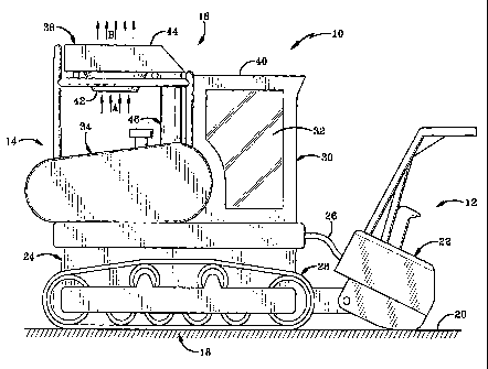
Fig. 1 is a side elevational view of the off-road vehicle of the present
invention.
Fig. 2 is a sectional view of the upper portion of the vehicle showing the fan
and
cooling boxes within a housing separate from the engine compartment.
Fig. 3 is a sectional view of the housing from above showing the fan and
cooling
boxes disposed within the housing.
Fig. 4 is a sectional view looking rearward and showing the engine compartment
and the elevated housing with the cooling boxes therein.
Similar numbers refer to similar parts throughout the drawings.
DETAILED DESCRIPTION OF THE INVENTION
The vehicle and cooling system of the present invention is indicated generally
at
10 in Fig. 1. Vehicle 10 is in particular a forestry tool, although vehicle 10
represents off-
road equipment in general. Vehicle 10 has a front 12, a rear 14, a top 16 and
a bottom
18 which is seated on and runs along a supporting surface 20 which is
typically the
ground or earth. Vehicle 10 includes a work assembly 22 which during operation
engages surface 20 and stirs up dust and various debris which rises into the
surrounding
air. Work assembly 22 is configured to remove trees and shrubbery from surface
20 and
also grind up the wood of such trees and shrubbery as vehicle 10 moves along
surface
20. Other off-road equipment represented by vehicle 10 may include alternate
work
assemblies which perform other types of off-road work.
Vehicle 10 includes a frame 24 on which work assembly 22 is movably mounted
and from which work assembly 22 extends outwardly in a forward direction.
Assembly 22
is hydraulically operated via hydraulic lines 26. Tracks 28 (only one shown)
are mounted
on frame 24 and revolve in a standard manner to move vehicle 10 along surface
20. An
operator's cab 30 is mounted on frame 24 at the front end thereof and includes
at least
one window 32 to allow the operator to view work assembly 22 and so forth.
Preferably,
cab 30 is an air-conditioned cab and is thus substantially sealed from the
external
environment when the door thereof (not shown) is closed. An engine compartment
34 is

CA 02659306 2009-01-28
WO 2008/016525 PCT/US2007/016730
3
mounted on frame 24 about midway between top 16 and bottom 18 behind cab 30
and
houses an engine 36 (Fig. 4) which is mounted on frame 24 for powering the
various
aspects of vehicle 10, such as tracks 28, work assembly 22 and so forth.
An elevated cooling housing 38 is mounted on frame 24 behind cab 30 at or
adjacent top 16 and includes a portion which is the same height as an upper
end or top
40 of cab 30. Housing 38 is spaced upwardly from and distal compartment 34.
Housing
38 defines a downwardly opening air intake 42 and an upwardly opening exhaust
port 44
disposed directly above intake 42. Each of intake 42 and port 44 is open to
the external
atmosphere or air surrounding vehicle 10. A pipe 46 extends upwardly from
compartment
34 to a forward portion of housing 38 and defines a passage 48 (Fig. 4) which
communicates with an interior chamber 50 of engine compartment 34 and an
interior
chamber 52 of housing 38. An intake filter 54 is disposed adjacent intake 42
and an
exhaust filter 56 is disposed adjacent exhaust port 44. A fan 58 is disposed
within interior
chamber 52 of housing 38, as are several heat exchangers or cooling boxes 60.
More
particularly, these cooling boxes are disposed at a cooling location and
include an air-
conditioning coolant box 60A, a hydraulic oil box 60B and an engine coolant
box 60C
(Figs. 3 - 4). Fan 58 is typically an electrical fan having an electrical
motor 59 and fan
blades 61. Motor 59 is in electrical communication with the electrical system
of engine 36
and is powered thereby. The cooling system further includes a source 62A of
air-
conditioning coolant, a source 62B of hydraulic oil and a source 62C of engine
coolant
(Figs. 3-4). Source 62A is in fluid communication with,cooling box 60A via
feed and
return lines or conduits 64. Likewise, source 62B is in fluid communication
with cooling
box 60B via feed and return lines or conduits 66 and source 62C is in fluid
communication with box 60C via feed and return lines or conduits 68. Each of
sources
62 includes a pump powered by engine 36 for pumping the respective fluid
through the
respective conduits to the respective boxes 60 and back in a recirculating
manner.
Conduits 64, 66 and 68 all pass from interior chamber 50 through passage 48
into interior
chamber 52.
In operation, engine 36 is operated to drive the various moving parts of
vehicle 10.
More particularly, engine 36 drives tracks 28 in order to move vehicle 10 and
drive the
operation of work assembly 22 in order to perform the designated off-road work
as
previously mentioned. In order to provide cooling of the various liquids,
engine 36
provides electrical power or the like in order to operate fan 58 so that air
is drawn into

CA 02659306 2009-01-28
WO 2008/016525 PCT/US2007/016730
4
intake 42 as indicated at arrows A in Figs. 1 and 2 and exhausted from exhaust
port 44
as indicated at arrows B in Figs. 1, 2 and 4. The elevated nature of housing
38 and
intake 42 thereof significantly minimizes the amount of dust and debris which
is drawn
into the cooling system generally and the separation of housing 38 and
compartment 34
substantially eliminates the dust and debris which enters engine compartment
34. It is
noted that corripartment 34 is ventilated but has a minimal air flow. As air
passes through
housing 38, it passes around and through boxes 60 as indicated at arrows C in
Figs. 2-4
in order to remove heat from boxes 60, consequently removing heat from the air-
conditioning coolant, hydraulic oil and engine coolant flowing respectively
through boxes
60A, 60B and 60C. The various fluids which are cooled by this process then
return via
the respective return lines to sources 62 in order to provide air-conditioning
to cab 30, to
cool the hydraulic oil used in the various movements of, for instance, tracks
18 and work
assembly 22, and to provide cooling to engine 36. The rotation of fan blades
61 is shown
at arrows D in Fig. 3 and additional general movement of the air flow through
housing 38
is shown at arrows F in Fig. 4.
Thus, the elevated position of housing 38 provides a cooling system in which
the
amount of dust and debris moving through the intake thereof is substantially
minimized.
The positioning of fan 58 and cooling boxes 60 external to engine compartment
34 also
substantially eliminates the intake of dust and debris into the engine
compartment. In
addition, creating a separate and enlarged cooling housing, such as housing
38, allows
for a substantial increase in the area which can be provided for cooling boxes
60, which
are thus preferably enlarged compared to standard cooling boxes in order to
provide a
larger heat exchange area for more efficient cooling of the various fluids
passing
therethrough. Further, housing 38 is disposed distal work assembly 22 as far
as is
feasibly possible in order to minimize the amount of dust and debris entering
intake 42.
Moreover, the fact that cab 30 is disposed between intake 42 and work assembly
22 also
reduces the amount of dust and debris which will enter intake 42. In addition
to the
substantial reduction of dust and debris entering engine compartment 34, the
positioning
of housing 38 and the components therein external to compartment 34 make
cleaning
and maintenance much easier than when such components are disposed within the
engine compartment. Thus, the cooling system of vehicle1 O provides a remote
cooling
package which minimizes the dust and debris which is moved through the cooling
system

CA 02659306 2009-01-28
WO 2008/016525 PCT/US2007/016730
and engine compartment while also providing for a system that is more easily
maintained
and cleaned.
In the foregoing description, certain terms have been used for brevity,
clearness,
and understanding. No unnecessary limitations are to be implied therefrom
beyond the
5 requirement of the prior art because such terms are used for descriptive
purposes and
are intended to be broadly construed.
Moreover, the description and illustration of the invention is an example and
the
invention is not limited to the exact details shown or described.

Representative Drawing
A single figure which represents the drawing illustrating the invention.
Administrative Status

2024-08-01:As part of the Next Generation Patents (NGP) transition, the Canadian Patents Database (CPD) now contains a more detailed Event History, which replicates the Event Log of our new back-office solution.

Please note that "Inactive:" events refers to events no longer in use in our new back-office solution.

For a clearer understanding of the status of the application/patent presented on this page, the site Disclaimer , as well as the definitions for Patent , Event History , Maintenance Fee  and Payment History  should be consulted.

Event History

Description Date
Application Not Reinstated by Deadline 2015-01-29
Inactive: Dead - No reply to s.30(2) Rules requisition 2015-01-29
Deemed Abandoned - Failure to Respond to Maintenance Fee Notice 2014-07-25
Inactive: Abandoned - No reply to s.30(2) Rules requisition 2014-01-29
Inactive: S.30(2) Rules - Examiner requisition 2013-07-29
Letter Sent 2012-07-03
All Requirements for Examination Determined Compliant 2012-06-14
Request for Examination Requirements Determined Compliant 2012-06-14
Request for Examination Received 2012-06-14
Inactive: Cover page published 2009-06-10
Inactive: Notice - National entry - No RFE 2009-04-30
Inactive: IPC removed 2009-04-23
Inactive: IPC assigned 2009-04-23
Inactive: IPC removed 2009-04-23
Inactive: First IPC assigned 2009-04-23
Application Received - PCT 2009-04-17
National Entry Requirements Determined Compliant 2009-01-28
Application Published (Open to Public Inspection) 2008-02-07

Abandonment History

Abandonment Date Reason Reinstatement Date
2014-07-25

Maintenance Fee

The last payment was received on 2013-06-25

Note : If the full payment has not been received on or before the date indicated, a further fee may be required which may be one of the following

  • the reinstatement fee;
  • the late payment fee; or
  • additional fee to reverse deemed expiry.

Patent fees are adjusted on the 1st of January every year. The amounts above are the current amounts if received by December 31 of the current year.
Please refer to the CIPO Patent Fees web page to see all current fee amounts.

Fee History

Fee Type Anniversary Year Due Date Paid Date
Basic national fee - standard 2009-01-28
MF (application, 2nd anniv.) - standard 02 2009-07-27 2009-01-28
MF (application, 3rd anniv.) - standard 03 2010-07-26 2010-06-16
MF (application, 4th anniv.) - standard 04 2011-07-25 2011-05-03
MF (application, 5th anniv.) - standard 05 2012-07-25 2012-06-12
Request for examination - standard 2012-06-14
MF (application, 6th anniv.) - standard 06 2013-07-25 2013-06-25
Owners on Record

Note: Records showing the ownership history in alphabetical order.

Current Owners on Record
RAYCO MANUFACTURING, INC.
Past Owners on Record
JOHN M. BOWLING
Past Owners that do not appear in the "Owners on Record" listing will appear in other documentation within the application.
Documents

To view selected files, please enter reCAPTCHA code :


To view images, click a link in the Document Description column. To download the documents, select one or more checkboxes in the first column and then click the "Download Selected in PDF format (Zip Archive)" or the "Download Selected as Single PDF" button.

List of published and non-published patent-specific documents on the CPD .

If you have any difficulty accessing content, you can call the Client Service Centre at 1-866-997-1936 or send them an e-mail at CIPO Client Service Centre.


Document
Description 
Date
(yyyy-mm-dd) 
Number of pages   Size of Image (KB) 
Drawings 2009-01-27 4 130
Abstract 2009-01-27 2 81
Claims 2009-01-27 3 90
Description 2009-01-27 5 277
Representative drawing 2009-06-09 1 20
Notice of National Entry 2009-04-29 1 193
Reminder - Request for Examination 2012-03-26 1 118
Acknowledgement of Request for Examination 2012-07-02 1 188
Courtesy - Abandonment Letter (R30(2)) 2014-03-25 1 164
Courtesy - Abandonment Letter (Maintenance Fee) 2014-09-18 1 174
PCT 2009-01-27 2 68