Note: Descriptions are shown in the official language in which they were submitted.
CA 02659555 2009-01-30
1
METHOD FOR THE CONTINUOUS PRODUCTION OF A MULTIAXIAL
CONTEXTURE WEB
The invention relates to a method for the continuous production of a
multiaxial
contexture web, in which a contexture is shaped to form a multiaxial
contexture by
winding about a plane and it relates to a corresponding apparatus for carrying
out
the method.
Long fiber reinforced composite components constitute an important application
for
technical textiles. The configuration and structure of the reinforcement
textile
substantially determine the properties of the final composite component in
combination with the fabrication technology and the matrix material used.
Multiaxial
contexture webs, also designated as MD- or multidirectional contexture webs,
thus
play an important role, since compared to other textiles, they facilitate area
layouts,
which provide a better utilization of the specific properties of the fibers
employed,
while simultaneously reducing the production cost and thus component cost.
In order to produce multiaxial contexture webs, various techniques are
employed. It
is obvious to resort to a technology which is similar to weaving, wherein a
weft
thread is placed at an angle to the direction of extension of the contexture
web. This
method, however, is slow and only allows a slow production speed when the
fibers
are fine. A method has proven to allow much faster production, in which
uniaxial
contexture webs, also designated as UD- or unidirectional contexture webs are
formed into multiaxial contexture webs through winding about plane.
In the published patent application DE 10 2005 000 115 Al, a method for
producing
a multidirectional contexture web is disclosed, in which a contexture, whose
fibers
are oriented in the running direction of the contexture web, is circumwound by
two
additional webs at an angle relative to the running direction, which creates a
multiaxial contexture. Said multiaxial contexture thus comprises at least
three
layers. These are the two opposite layers of the contexture wound at an angle
and
the so-called zero-degree-web, which comprises fibers in running direction of
the
contexture web. Such a web has positive features with reference to tensile
strength.
CA 02659555 2012-04-03
2
The Japanese patent application JP 2003 221771A relates to a method for
producing a multiaxial contexture web, in which only the contexture webs,
which are
wound at an angle, are wound about two approximately hand wide bands, which
remain in the contexture. This method creates a multiaxial contexture, which
comprises reinforced edges. The reinforced edges, on the one hand, have the
advantage that the contexture comprises high toughness or high stability, in
particular, at the edges, on the other hand, said contexture has the
disadvantage
that it cannot be wound up on a roll in a stable manner, due to the increased
thickness of the material at the edges, and, on the other hand, it is not
hereby not
possible to establish layers of constant thickness of a fiber reinforced
plastic, since
the lateral bands increase the thickness of the contexture unnecessarily.
Thus, it is the object of the invention to provide a method for producing a
multiaxial
contexture, which overcomes the disadvantages of the prior art.
The object of the invention is accomplished by using tension elements as a
delimitation of the plane, about which the unidirectional contexture is wound,
wherein
the tension elements can be removed or separated after winding the contexture
web
thus produced.
Compared to the method disclosed in JP 2003 221771A, a pair of tension proof
tension elements is used according to the invention, which are used as a
winding
plane for the contexture webs, disposed at a slant angle relative to the
running
direction of the contexture. This creates a multiaxial contexture web, which
initially
only loosely adheres to itself internally and which is pulled through two
calendering
rollers after windup. Corresponding indentations are provided in the
calendering
rollers, in which the tension elements run, so that the distance of the
calendering
rollers can be selected independently from the tension elements. The calender
joins
the contexture webs firm enough, so that they form a firm multiaxial
contexture,
possibly using binder- or glue means. Additionally, there is the possibility
to use an
impregnation method or a fixation method upon the contexture together with the
tension elements or without the tension elements, so that the contexture can
be
wound up for further processing and becomes much easier to handle. Directly
after
the calendering or impregnation, the multiaxial contexture web can be
separated
CA 02659555 2009-01-30
3
from the tension elements by an edge side cut. In this cut, the removed
tension
elements are either wound onto an additional drum, wherein fibers, which
adhere to
the tension elements, can be optionally removed from the tension elements
before
they are wound up, but it is also possible to feed the tension elements back
into the
process instead of winding them up, so that the tension elements are run in a
continuous loop. Furthermore, it is possible to windup the tension elements,
and
after the contexture webs, from which the multiaxial contexture is produced,
have
been unwound, the wound up tension elements can be fed back into the process
by
feeding them back into the production process on an unwinding roll.
Furthermore,
there is the possibility to pull the tension elements out of the contexture
during
further processing, instead of cutting them off, as long as it is assured that
the
contexture does not adhere to the tension elements.
The unidirectional contexture is provided to the winding plane transversal to
its
running direction, wherein e.g. an angle of 450 can be enclosed between the
running
direction and the feed direction. Depending on the requirements, however, also
other angles between 0 and 90 degrees can be enclosed. Furthermore, it can
be
useful to provide a third web of a uniaxial contexture, which is positioned
e.g.
between the transversally fed uniaxial contextures. This three layer
multiaxial
contexture thus produced is suitable in particular to absorb tensile stress in
longitudinal direction of the multiaxial contexture, which can occur e.g. by
pulling the
multiaxial contexture off from the winding plane. This additional third layer
can be
comprised of the same material as the uniaxial contextures, supplied at a
slant
angle, or it can be comprised of another suitable material. Thus, e.g. a third
layer
can be supplied as a gluing grid or as an adhesion grid, by which abutting
layers of
uniaxial contexture can be glued to one another.
It is furthermore advantageous, when the indentations in the enveloping
surface of
the calender rollers are configured, so that tension forces occurring in
longitudinal
direction in the multiaxial contextures only occur in the portion of the
indentations,
this means in the portion of the tension elements disposed in the multiaxial
contexture, and the remaining portion of the multiaxial contexture, which is
centrally
located between the tension elements, remains substantially free of tension.
This
CA 02659555 2009-01-30
4
configuration facilitates the production of a high quality multiaxial
contexture in a
simple manner.
It is furthermore suggested to treat the multiaxial contexture after
calendering with a
spiked roller or with a needle bar, this means it is provided with holes,
which are
configured so that the resin, employed for a possible subsequent drenching of
the
multiaxial contexture, penetrates well into the multiaxial contexture, in
order to
provide a material of consistent high quality. The holes thus imparted into
the
multiaxial contexture can be imparted into the multiaxial contexture with
various
patterns.
In order to perform the methods, there are two different variants in
principle. In a first
variant, two rollers are used in the process, which store unidirectional fiber
material
contextures. Said rollers are disposed on a fixed axis. The rollers from which
the
unidirectional contexture is taken off are thus disposed opposite to one
another, and
an assembly is installed between the rollers, in which the two tension
elements,
which are used as a delineation of the winding plane for the unidirectional
contexture, are unwound and run through two calendering rollers. Thus, the
tension
elements can be removed before the calendering, wherein the calendering
rollers
provide the necessary mechanical tension to the contexture. Alternatively, the
tension elements can be removed after the calendering. The two tension
elements
are then rotated about an axis, which is disposed central parallel with
respect to the
two tension elements, and thus wind the uniaxial contexture off from the
rollers,
which provide the uniaxial contexture, and wind it about the plane, which is
defined
by the two tension elements. One pair of calendering rollers rotates together
with
the plane, which rotates together with the two tension elements, and devices,
which
also co-rotate, are disposed proximal to the calendering rollers, which remove
the
tension elements from the edge of the multiaxial contexture before or after
calendering, e.g. by a cut. Thus, the tension elements are wound up in
parallel to
the multiaxial contexture or they are fed back into the process. Cleaning the
cutoff
tension elements from residual fiber or binder rests is an optional step.
Since
laterally open fibers are created by the cut in the multiaxial contexture, it
has proven
advantageous when the lateral edges of the multiaxial contexture are also
purled by
CA 02659555 2009-01-30
a respective device, so that the contexture does not tend to fray at its
sides, which
would render the multiaxial contexture more difficult to work with.
In a second embodiment of the method according to the invention it is also
possible
that the entire device, in which the tension elements are wound off and wound
up
5 again, the calendering roller pairs and the cutting- and purling device
are held
stationary, while the two rollers with the unidirectional contexture are wound
about
the plane of the tension elements.
In both embodiments, there is a relative movement of the plane, which is
defined by
the tension elements, relative to the material with the uniaxial contexture,
which is
stored on the rollers and wound onto the plane.
In order to stabilize the winding process, it is provided that the tension
elements are
scored in a preferred embodiment of the method according to the invention, or
that
the tension elements are provided with a binder- or glue means. Scoring the
tension
elements or the binder or the glue coating of the tension elements makes the
tension
elements grip the contextures more safely, from which the multiaxial
contexture is
fabricated, which causes the contexture thus created to be formed more evenly,
and
causes the unwound unidirectional contexture not to tend to slide during the
calendering process and during the subsequent separation process. Thus, a
contexture can also be used in another embodiment of the method according to
the
invention, which contexture comprises a small amount of binder, so that the
uniaxial
contextures wound into one another adhere to one another, which provides a
more
stable contexture web. Thus, it is also possible that a so-called prepreg is
used as a
base material, in which the fibers are already provided with a binder that has
not
hardened yet, or with non-polymerized glue, which can be hardened optionally
in an
optional subsequent process. Additionally, it is also possible to use an
adhesion
thread grid for stabilizing the contexture webs, wherein said contexture web
is wound
off and guided between the tension elements and connects the webs with one
another.
A multiaxial contexture web thus produced can be made of various fiber
materials. It
is possible to use bound textiles as a base material for the multiaxial
contexture web.
Cloths can be used, knitted materials, but also fleeces or single fibers in
unidirectional or multidirectional patterns, rovings, threads or fiber layers.
CA 02659555 2009-01-30
6
The material, from which the fibers are made, can be glass-, carbon- or aramid
fibers, alternatively, natural fibers like flax, jute, or sisal can be used,
but it also
possible to use plastic fibers like polypropylene, PBO, polyester or
polyethylene.
The tension elements employed can be made of wires or bands, which may be made
of metal. Alternatively, there is the possibility to use plastic material,
wherein
preferably the contexture material is used, so that furthermore there is the
possibility
to feed the finished contexture together with the tension elements to the
subsequent
production process. In this case, the tension elements certainly do not have
to be
separated from the contexture.
In order to perform the method, a device is provided, which provides at least
one
winding roll for fiber material, a calendering unit and possibly a separation
unit and
rolls for winding up and unwinding the tension elements, wherein the tension
elements are pulled off in parallel from rollers and thus are held in a plane,
which
defines the plane for circumwinding the contexture. Additionally, this device
can be
combined with a separation unit, so that the tension elements can already be
removed shortly after the winding process. Alternatively, there is the
possibility that
the contexture is run through an impregnating unit together with the tension
elements, so that a flexible, but internally stable contexture is provided
after
hardening. After the impregnating unit, at the latest, the tension elements
can be
removed, or in case they are made of contexture material themselves, they can
remain in the contexture.
The invention furthermore relates to a method for producing of a multiaxial
contexture, preferably made of carbon fibers, in which a monoaxial contexture
from
at least one storage device is wound about a winding plane, wherein the
winding
plane and the at least one storage device rotate about one another, in order
to wind
the monoaxial contexture about the winding plane, and the invention relates to
a
corresponding device for performing the method according to the invention.
In order to produce fiber reinforced plastics, contextures made of fibers are
used,
which are transfused by a plastic material. The compound made of plastic and
fibers
provides high stability with respect to tension to the fiber reinforced
plastic, wherein
CA 02659555 2009-01-30
7
the tension stability depends on the orientation of the fibers provided in the
contexture. Fiber reinforced plastics are primarily used where a high load
bearing
capability is required in combination with low weight, like e.g. in aircraft
or naval
construction. In order to provide fiber reinforced plastics with minimum
weight, it is
necessary to keep the amount of plastic material applied to the fibers as low
as
possible, wherein the plastic material should completely encapsulate the
fibers.
When using woven fibers, the fiber layer becomes relatively thick compared to
the
thickness of the fibers and thus requires more plastic material, which leads
to a fiber
reinforced plastic component with an increased layer thickness, and thus high
weight. In practical applications, contextures of fiber materials are used
increasingly,
in which the particular fibers are uniformly disposed and do not cross over
one
another, in order to keep an increase of the layer thickness of the fiber
material, and
thus the plastic material requirement of the fiber material as low as
possible. Since it
is known that the plastic material only has high tensile strength in the
direction of the
fibers, multiaxial contextures are used, in which the fibers are laid in
plural planes,
wherein the fibers comprise a preferred direction in each plane and preferably
do not
cross over one another. The simplest multiaxial contexture thus produced is a
contexture in which two webs of a fiber arrangement are placed over one
another, so
they cross over one another. Such contextures are produced either by placing
single
portions of a contexture web adjacent to one another at an angle to the web,
wherein
initially a lower layer and subsequently an upper layer is assembled from
particular
portions. Herein, particular diamond shaped portions are assembled into long
webs.
This method, however, is not suitable to economically produce larger
quantities, like
they are necessary for industrial production processes.
Another method thus resorts to winding one or two webs about a plate at an
angle,
and to pull the coil thus created off from a plate. This process can be
performed
continuously, wherein the coil is pulled off from the plate, and subsequently
compressed to form a contexture. Such a method has proven difficult to
implement
in practical applications, in particular, when the fibers almost have fluid
properties,
like it is the case for carbon fibers. This means that the fibers, due to
their low
weight and low surface friction easily fall over one another, and thus
counteract the
forming of a uniform contexture web. The more fluid the behavior of a
contexture
becomes, the more difficult is the production of a uniformly shaped multiaxial
CA 02659555 2012-04-03
8
contexture. When winding about the plate, it is necessary that the contexture,
which
lies at the bottom and on the plate, does not tend during continuous pull off
from the
plate that the particular fibers roll off from the plate, thus having a twist
which leads
to the fibers curling or crossing over one another after the contexture is
pulled off.
The crossover renders the contexture qualitatively inferior to unusable
compared to a
continuously formed multiaxial contexture, which does not comprise any
crossovers.
The rollover of the fibers occurs in particular when the contexture is wound
onto the
winding plate under comparatively high tension. However, when the contexture
is
loosely placed about the plate, the particular fibers are able to cross over
one
another or to form loops, when they slide off the plate. This also leads to a
result
with inferior quality or unusable quality.
It is the object of the invention to provide a device and a method, in which a
monoaxial contexture is formed into a multiaxial contexture through winding
about a
plate, wherein friction when pulling the coil from the plate shall be avoided
as far as
possible in order to obtain an evenly formed multiaxial contexture.
The object according to the invention is accomplished by using at least one
belt- or
band drive at the opposite sides of the winding plane.
The winding plane, about which a monoaxial contexture is wound, comprises a
thickness, so that a belt- or band drive can be housed within the plate, which
is used
as a winding plane. Though the thickness of the winding plane increases
substantially, so that the coil is formed into a hose, when it is pulled off
the winding
plane, which hose has to be shaped into a contexture in a subsequent step, but
the
dimensions of the belt- or band drive at opposite sides of the winding plane
facilitate
housing a mechanism, which facilitates a completely friction free pulling of
the coil
from the winding plane. The fibers do not slide on a surface and do not roll
off from
said surface either, but the belt- or band drive continuously transports the
coil
forward and thus releases the coil at the end of the winding plane. Contrary
to a low
friction configuration of a winding plane e.g. by coating it with a surface,
which
comprises low friction resistance, it is provided here that the winding plane
is
preferably formed by at least one band drive.
CA 02659555 2009-01-30
9
It is provided in an advantageous embodiment of the present invention that a
cross
over guide for the belt or band is provided in the method and in the
corresponding
device, wherein the belt or the band is freely guided at opposite sides of the
winding
plane. It is accomplished by a cross over guide of the belt or of the band
that the
driving at opposite sides of the winding plane is completely uniform. This
allows
doing away with a synchronization assembly of two drives which leads to a
simplified
configuration of a mechanism according to the present invention. Thus, it is
very
important for the driving at opposite sides of the winding plane that the
winding plane
comprises the same velocity at any given point in time so that a twisting of
the
particular fibers is avoided through a synchronous movement of both sides.
Through
the cross over guide of a belt or of a broad band it is accomplished that the
belt or
the band lays flat in the center between the two outer edges or winding
surfaces,
wherein the distance at both outer edges of the belt or of the band has the
same
length in the cross over guide. Through a cross over guide of the belt or the
band it
is assured that the belt or the band neither has to expand nor contract, which
facilitates the use of a belt or a band which is also inflexible in driving
direction.
Such a belt or a band can be highly taunted and facilitates a rigid
configuration of the
device according to the invention.
In order for the sensitive fibers not to touch moving parts when they are
folded into a
multiaxial contexture, it is provided that a minimal protrusion of the belt or
of the
band beyond the drive- and guide rollers is provided at the corner of the
winding
plate. In the method according to the invention and in the device according to
the
invention four vertically disposed drive- and/or guide rollers are provided at
the
corners of the plate provided as a winding plane. These are bracketed
approximately in the center by means of an axle in a bearing. The protrusion
of the
belt or of the band beyond the width of the drive and/or guide rollers has the
effect
that the fibers which are taunted over the belt or over the band are
transported over
the bracketing and the bearing without the fibers coming into contact with
said
moveable parts. The amount of the protrusion thus has to be selected, so that
a
mechanism which may be present for bracketing the drive- and/or guide rollers
is
disposed within the height of the protrusion. Through the cross over guide of
the belt
or of the band it is accomplished that the belt or the band, due to the
rotation,
requires less height but more width in the center of the winding plate
relative to the
CA 02659555 2009-01-30
dimensions at the sides. To reduce the height hereby is an essential
prerequisite for
guiding the very sensitive fibers, so that they do not come into contact with
movable
components or with components, whose velocity is different than the driving
velocity.
In an advantageous embodiment of the invention it is provided that a profile
belt or a
5 profile band is used, which comprises at least one profile ridge towards
the drive side
of the profile belt or of the profile band. Through the at least one profile
ridge on the
drive side of a profile belt or of the profile band it is accomplished that
the belt or the
band can be guided about the drive- or guide rollers, wherein forces can
possibly be
created at the rollers through the rotation which cause the belt or the band
to slip off
10 the drive- or the guide rollers. These forces can occur when the profile
rollers are
not absolutely parallel to one another and when one respective pair is not
aligned so
that is lies in a plane. The profile belt or the profile band thereby
compensate minor
misalignments of the drive- and/or guide rollers.
In a particularly advantageous embodiment of the invention the profile belt or
the
profile band comprises plural profile ridges facing towards the drive site, so
that the
belt or the band can be highly tautened without thereby letting the lateral
shear
forces at the profile ridge become high enough due to the high tension, so
that a
premature wear of the belt or of the band occurs. When profile belts or
profile bands
are used, the drive- and/or guide rollers have a negative shape which
corresponds to
the profile belts or to the profile bands, so that the drive and/or guide
rollers safely
receive the longitudinal profiles of the belt or of the band, thereby guiding
the belt or
the band.
In another advantageous embodiment to the invention the profile belt or the
profile
band comprises an additional teething, so that the belt or the band can be
driven by
the teething safely and without slippage.
In order for the winding plane and the storage device for a monoaxial
contexture to
be able to rotate about one another, it is furthermore provided in an
advantageous
embodiment of the invention that the belt or the band comprises a profiling
with
profile grooves extending transversal to the running direction of the belt or
of the
band. These profile grooves comprise a width which corresponds to the
dimension
of the width of a fiber. Hereby it is assured that the fibers wound onto the
winding
plate come to rest in the fine profile grooves on the outside of the belt or
of the band
CA 02659555 2009-01-30
11
and do not tend to cross over one another or twist due to slightly
asynchronous
movements of winding plate and the storage device, since the fine profile
grooves
keep the fibers in place.
It is provided in the method according to the invention that tension rollers
are used,
which are aligned perpendicular to the drive- and/or guide rollers which are
disposed
transversal to the orientation of the belt or of the band. These tension
rollers are
preferably disposed in the center or proximal to the center of the winding
plane,
where the belt portions cross over one another flat. Through the tension
rollers it is
prevented that the belt portions can touch one another due to oscillations,
thus
leading to a premature wear and abrasion. Thus, it is provided that the
tension
rollers do not only influence the path of the roller or of the band in the
interior of the
volume of the winding plane, but it is also provided that the tension rollers
tighten the
belt or the band, so that the belt or the band does not tend to contract in
the middle
during winding, wherein the fibers have a smaller diameter when being wound
around the winding plane, than necessary to slide over the two drive- or guide
rollers, and they could thus tear when being pulled off from the winding
plane.
For improved tightening capabilities of the belt or of the band it is provided
that the
belt or the band comprise a steel belt, which makes the belt or the band
particularly
inflexible in driving direction. Hereby the belt or the band can be tightened
very hard,
so that the belt or the band do not tend to contract in the middle when carbon
fibers
are wound around them, as long as the tension of the fibers is not so high
that the
elasticity of the steel belt causes the belt or the band to contract in the
middle
between the two drive- and/or guide rollers. Thus it is not absolutely
mandatory that
the belt or the band comprises a steel belt, but it is also possible that a
textile
reinforced belt or band is used, wherein besides natural fibers also carbon
fibers
Kevlar0-fibers can be used.
In another embodiment of the method according to the invention a convex
surface at
the upper side and at the lower side of the winding plane is provided, which
covers
the belt- or band drive in the interior of the winding plane. Thus, it is also
possible to
do without a cross over guide of the belt or of the band. It is also possible
to dispose
the convex surfaces at the sides and to provide the upper and the lower
surfaces of
the winding plane with moving bands, so that the larger surfaces transport the
CA 02659555 2012-04-03
12
multiaxial contexture without friction and the side surfaces transport it with
low
friction.
The invention relates to a method for the production of a multiaxial
contexture made
of fibers, in particular, carbon fibers, in which a unidirectional contexture
web is
wound about a plate at an angle to form a coil, wherein the plate is provided
with a
device for compensating friction and the coil is pulled off from the plate.
It is the object of the present invention to provide a method which
facilitates to pull
the fiber coil off from a plate, so that a uniformly shaped multiaxial
contexture with
two planes is provided.
The object according to the invention is accomplished by using a cascade
guide,
which is disposed at the end of the plate and which comprises a laterally
protruding
wedge.
The cascade guide according to the invention comprises a wedge at the end of
the
plate as its main component, which transforms the hose shaped coil at the end
of the
plate, about which a monoaxial contexture is wound, into a flat folded web,
comprising two planes. The wedge thus comprises a particular geometry, which
causes the coil to be transformed into the multiaxial contexture smoothly and
without
forming distortions at the edges of the contexture web. The base area of the
wedge
thus comprises an identical geometry relative to the cross sectional area of
the plate
and it is disposed directly at the plate. Depending on the provision of an
assembly to
reduce the friction on the plate, however, a gap is provided to run possibly
moving
portions by the wedge below the wedge. The two main sides of the plate facing
away from one another, thus the upper and the lower sides of the plate, are
extended by the wedge in a trapeze shape. On the other hand, the sides of the
plate
with finite thickness are joined by the wedge to form a triangular shape,
wherein the
base of the triangle has the same width as the thickness of the plate and the
triangles laterally guide the contexture beyond the width of the plate. The
trapeze,
which is disposed at the upper- or lower side of the plate, comprises a base,
which
corresponds to the width of the contexture, wherein the width of the
contexture is not
quite reached in order not to run the contexture on the wedge under mechanical
tension.
CA 02659555 2009-01-30
13
In a particularly preferred embodiment of the cascade guide according to the
invention, the wedge comprises a lug at its end, thus where the two trapezes
join
with their bases. The lug has the advantage that the coil, which is almost
folded into
a flat web, is smoothly pulled off from the wedge.
In another advantageous embodiment of the invention, the wedge comprises a
small
bead at the lateral points, which seamlessly transitions into a bead at the
edges of
the lug, in order to reduce the friction resistance at the lateral edges of
the lug.
The width of the bases of the two trapezes of the wedge is thus selected, so
that it is
wider, than the width of the winding plate, exactly by the thickness of the
winding
plate. Also here, a slight undersize is provided, in order not to let the coil
slide off
from the wedge under load.
In a particular embodiment of the invention, the wedge in the cascade guide
comprises a base area, which is identical to the cross sectional area of the
plate, and
comprises tetrahedron shaped extensions, which laterally protrude beyond the
edges of the plate in the plane of the plate, whereby the two planes of the
plate are
extended by trapezes of the wedge, which taper into one another, and wherein
the
width of the base of the two trapezes is increased relative to the width of
the plate by
the thickness of the plate. The length of the wedge has to be adapted to the
flow
properties of the coil. The more flow capable the coil, the longer the wedge
has to
be selected, in order to prevent the minor movements of the particular fibers
at the
rims of the winding plate during deformation of the coil into a flat
contexture, and
thus assure the uniformity of the multiaxial contexture webs thus produced
with the
lowest complexity possible.
In another embodiment of the invention, the cascade guide comprises rollers
next to
the wedge, in order to guide the coil on the wedge. The configuration of the
method
according to the invention is thus characterized by using particular rollers
in the
cascade guide, which are driven at the velocity of the contexture, so that the
rollers
neither slow down nor drive the contexture and so that they press it onto the
wedge.
The rollers are advantageously controlled by sensors, so that the rollers
neither slow
down the contexture, thus upsetting the contexture when pulling the coil off
from the
plate, nor tear the coil apart by driving it forward. Since the particular
contextures
are not stable against a distortion of the particular webs in plural
directions like a
CA 02659555 2009-01-30
14
textile material, it is important that in particular the compression rollers
press the
contexture onto the wedge in an ideal scenario without force with respect to
driving
the contexture forward or slowing the contexture down in order to prevent that
distortions form when the coil is pulled off from the plate and shaped into a
contexture.
In an advantageous embodiment of the invention, at least two roller assemblies
are
used, each comprising rollers disposed on a common axis, wherein different
roller
assemblies comprise different speeds, adapted to the speed of the unwinding
coil.
When the coil is formed into a uniform contexture, slightly different
directions of
movement occur within the web, which comprise directional components, pointing
laterally out of the web with respect to the drive direction of the web. These
directional components can be configured with different thickness at different
locations. Thus, it has proven advantageous not to use a continuous roller in
the
cascade guide, but to use particular rollers respectively adapted to the local
velocity
of the web, wherein said rollers are disposed on one axle assembly. This
prevents
inconsistencies from occurring through an adaptation of the roller velocity to
a mean
drive velocity of the coil, which could lead to distortions in the multiaxial
contexture
web. At least two roller assemblies are advantageously used, which are
disposed
behind one another, and which are added depending on the length of the wedge,
so
that the coil is uniformly pressed against the wedge over the entire surface
of the
wedge.
In another advantageous embodiment of the invention, at least two roller
assemblies
are used in the cascade guide, each comprising rollers disposed on a common
axis,
wherein different roller assemblies comprise different axis orientations
adapted to the
flow direction of the pulled off coil. The rollers, which press the coil onto
the wedge,
are not only exposed to different velocities of the coil when forming the coil
into a
multiaxial contexture web, but they also experience different flow directions.
In the
center of the plate, the flow direction is equal to the web direction. At the
sides of the
wedge, where the vertical side surface of the winding plate tapers into a
triangle and
where it is run around the edge of the laterally extended wedge, the
components of
the coil have a slightly different flow direction. This configuration of the
invention
facilitates that the rollers are adapted according to the flow direction,
which is
CA 02659555 2009-01-30
provided by the shape change. This prevents that distortions form in the
multiaxial
contexture web when the coil is formed into the contexture web.
It has proven advantageous to pull the contexture over a lug at the end of the
wedge,
which lug is disposed at the end of the wedge and comprises an approximately
5 rectangular shape with very small wall thickness. This provides the
ability to the
contexture to align on the lug without forming distortions due to the lack of
a support
frame.
In order to reduce the friction at the edges of the lug, it is provided to
configure the
edges with a slightly pronounced bead, wherein the bead is configured, so that
the
10 fibers can loop around said bead without breaking. Thus, the
characteristic of the
bead is highly dependent on the bending capability of the fibers used in the
contexture. In order to support the flow of the coil during forming, it is
provided that
the coil is slightly rounded at the edges and that the points of the wedge end
in a
small bead in order to provide a smooth transition from the wedge into the
lug,
15 wherein said bead seamlessly transitions into the lug.
Thus, it has proven advantageous, when the bead is slightly tapered towards
the end
of the lug. Through the tapered bead, the mechanical winding tension about the
lug
is slightly reduced during pull off. Alternatively or cumulatively with that,
also the
geometry of the lug can be slightly trapezoid, so that the lug is tapered
relative to the
width of the wedge where the formed coil is taken off the lug. Also, this
taper
facilitates a reduction of the mechanical tensions when pulling off the coil.
In a particularly advantageous embodiment of the invention, the components of
the
cascade guide are provided with a friction reducing surface. Surfaces made of
a
polyfluorized polymer have proven particularly advantageous for this
application and
a surface of diamond type carbon has proven highly advantageous in particular,
wherein said carbon material comprises a particularly low friction relative to
carbon
fibers. This prevents the generation of friction forces, which cause a non-
uniform
forming, and thus create inconsistencies in the formed coil.
The invention furthermore relates to a method for producing a multiaxial
contexture,
preferably made from carbon fiber materials, in which a monoaxial contexture
is
wound from at least one storage device about a winding plane, wherein the
winding
CA 02659555 2012-04-03
16
plane and the at least one storage device rotate about one another in order to
wind
the monoaxial contexture about the winding plane. The invention also relates
to a
corresponding device for performing the method.
It is furthermore the object of the invention to provide a method for
producing a
multiaxial contexture and a device for performing the method, which overcome
the
disadvantages of the prior art.
The object is accomplished according to the invention by using a vibration
drive,
which causes the winding plane to vibrate mechanically.
In the method for producing a multiaxial contexture, a monoaxial contexture is
unwound from a storage device, preferably provided as a roller, and wound
about a
winding plane at an angle. For this purpose, the winding plane and the at
least one
storage device rotate about one another, so that the monoaxial contexture is
wound
by the storage device about the winding plane. In order to be able to pull the
wound
contexture off from the winding plane, it is provided according to the
invention to use
a vibration drive, which causes the winding plane to vibrate mechanically. The
vibrations thus have low amplitude and comparatively high frequency. Thus, it
is
provided in a preferred embodiment that the vibration parallel to the side
edges
caused by the oscillations follows a certain profile in the time distance
diagram, so
that the particular fibers are transported in a preferred direction. It is
also possible to
perform the vibration in other directions with reference to the side edges of
the
winding plane. When the mechanical oscillation is performed without preferred
direction, then the fiber laid around the winding plane is not in direct
contact with the
winding plane for long periods of time, since it is pushed away from the
winding
plane by mechanical oscillations. Within this short period of time it is
possible to pull
the contexture from the plate with little friction resistance, thus it is
irrelevant that not
all fibers are simultaneously lifted from the winding plane, since the mean
friction is
significantly reduced by the vibration. However, when the vibration is
performed in
parallel to the lateral surfaces of the winding plane, it is possible by a
certain type of
vibration control to transport the particular fibers of the contexture web in
a preferred
direction. When the winding table is caused to vibrate with short amplitude
and
without certain preferred directions, the contexture can be pulled off from
the plate
CA 02659555 2009-01-30
17
with little resistance. However, when the frequency is adapted to the friction
of the
contexture on the winding plane, so that the fiber is transported by the
friction
resistance through a slow movement in the pull off plane, and the friction
resistance
transitions from static friction to dynamic friction through a quick reversal
movement,
wherein the inertia of the fibers prevents a fast backslide of the fibers on
the winding
plane, then the contexture is transported in pull off direction. Through the
two
different velocities of the mechanical oscillations in pull off direction and
in reversal
direction, a transport of the fibers is accomplished. When oscillating in pull
off
direction, the winding plane moves slowly forward. During this slow movement,
the
fiber is under static friction on the surface of the winding plane and is
thereby moved
forward by the plate. During the quick reversal movement of the winding plane,
the
fiber transitions from a static friction state into a dynamic friction state,
wherein the
winding plane moves back below the fiber without the fiber following this
reversal
movement. This way, the entire contexture is continuously moved forward. It is
an
advantage of the vibration drive that the contexture is transported along the
winding
plane instead of the unavoidable friction of the contexture on the winding
plane
without the particular fibers tending to cross over, which facilitates the
production of
a uniform contexture.
Thus, it is possible to create a low friction state of the contexture on a
winding plane
through a non-oriented vibration, and it is possible to create an oriented
vibration
through an oriented vibration with different velocities in different
oscillation directions,
which causes the fiber to be transported in a preferred direction. The
oriented
vibration is suitable for such methods and devices for producing a multiaxial
contexture by pulling the multiaxial contexture off from the winding plane. On
the
other hand, the oriented vibration is suitable for such methods and devices
where
the multiaxial contexture is not pulled off from the winding plane by an
additional
device or where it slides off the winding plane due to gravity, but the
contexture is
driven forward by the vibration.
A vibration drive is advantageously used by the method according to the
invention,
which generates mechanical oscillations with substantially saw tooth
configuration
with respect to the time-distance-diagram. Thus, the steeper flank of the
oscillation
movement in the time-distance-diagram is oriented against the pull off
direction and
CA 02659555 2009-01-30
18
the less steep flank of the oscillation movement in the time-distance-diagram
is
oriented in the pull off direction of the contexture. Through this saw tooth
type
character with reference to the time-distance-diagram, a transport of the
fibers on the
winding plane is advantageously achieved, so that an additional device for
pulling off
the contexture can be omitted.
In order to adjust the friction of the fibers on the winding plane, it is
possible to impart
fine structure onto the winding plane. Through the fine structuring, a defined
friction
resistance of the fibers on the winding plane can be achieved, so that the
oscillation
amplitude and the oscillation frequency can thus be adjusted. For example, it
is
hereby possible to adjust the vibrations to low frequency and low amplitude,
which is
necessary for a uniform forward movement of the particular fibers. Through the
lower amplitude and the lower frequency, a substantially wear reduced
configuration
of the device for performing the method according to the invention becomes
possible, and the device requires less energy in order to make the winding
plane
oscillate. It is furthermore possible to choose the weight and the elasticity
of the
winding plane, so that the resonance frequency of the winding plane
corresponds
exactly to the frequency which is necessary for transporting the fibers on the
winding
plane. It is up to the discretion of a person skilled in the art to set the
correct
parameters for the fine structures, the weight, the elasticity, the frequency
and the
amplitude of the oscillations through experimentation.
In an advantageous embodiment of the invention, the forward drive velocity of
the
fibers of the contexture on the winding plane is synchronized through the
vibration
drive with the relative rotation velocity of the storage device about the
winding plane.
Thus, during the time period of a half relative rotation of the storage
devices about
the winding plane, the forward driving is performed by the tangent of the
winding
angle a, which is measured between the orientation of the side edges of the
winding
plane, and the alignment of the fibers of the monoaxial contexture, multiplied
by the
width of the winding plane. By synchronizing the forward drive velocity with
the
relative rotation of the storage device about the winding plane, a continuous
winding
process is implemented, in which the contexture web forms a multiaxial
contexture
without forming a winding seam.
CA 02659555 2009-01-30
19
Since the winding plane has a finite thickness, it may be necessary to vary
the drive
velocity through the vibration drive during the winding process. During the
winding
process, the monoaxial fibers are tightened by two different edge types with
respect
to the rotation. On the one hand, the monoaxial fibers are tightened during a
quarter
relative turn by an edge, so that the fibers of the monoaxial contexture are
laid onto
an upper or lower surface of the winding plane, and, on the other hand, the
fibers are
tightened during a quarter and relative rotation of the monoaxial contexture
by an
edge, so that the fibers of the monoaxial contexture are laid onto a narrow
side edge
of the winding plane. In order for the driving to always be synchronized and
so that
no winding seams form, it is thus necessary to synchronize the driving by the
vibration drive with the different tension states of the fibers of the
monoaxial
contexture. Thus, the vibration drive has to be set faster during winding onto
the
upper or lower surface, than when the fibers are wound onto the side surfaces
of the
winding plane. Thus, the drive velocity is varied by the vibration drive
during a
relative rotation of the at least one storage device about the winding plane.
The
drive velocity is adapted to the product of the tangent of the winding angle
a, which is
measured between the orientation of the side edges of the winding plane and
the
orientation of the fibers of the monoaxial contexture and the width of the
winding
plane per quarter rotation of the winding plane, when the fibers of the
monoaxial
contexture are tightened by a side edge of the winding plane and wound onto a
surface of the winding plane. On the other hand, the drive velocity is adapted
to the
product of the tangent of the winding angle, which is measured between the
alignment of the orientation of the side edges of the winding plane and the
orientation of the fibers of the monoaxial contexture and the thickness of the
winding
plane per quarter rotation of the winding plane, when the fibers of the
monoaxial
contexture are tightened by a side edge of the winding plane and wound onto a
side
edge of the winding plane.
Advantageously, an oscillation frequency of 1 to 500 Hz, preferably 2 to 100
Hz,
particularly preferably 3 to 50 Hz, and overall preferably 5 to 50 Hz, is
selected for
the method according to the invention.
CA 02659555 2012-04-03
Thus, advantageously an amplitude of the oscillation of 0.001 cm to 10 cm,
preferably 0.01 cm to 5 cm, particularly preferably 0.1 cm to 1 cm, and
overall
preferably 0.2 to 0.5 cm, is selected.
The invention furthermore relates to a method for producing a multiaxial
contexture,
5 preferably made of carbon fiber materials, in which a monoaxial
contexture from at
least one storage device is wound about a winding plane, wherein the winding
plane
and the at least one storage device rotate about one another, in order to wind
the
monoaxial contexture about the winding plane, and the invention relates to a
corresponding device for performing the method according to the invention.
10 It is furthermore the object of the invention to provide a method and a
device which
facilitate to pull the fiber coil off from a plate, so that an evenly formed
multiaxial
contexture is made of two planes, wherein the pull off should not lead to
distortions
or twisting of the particular fibers of a monoaxial contexture.
According to the invention, the object is accomplished by placing the
longitudinal
15 axis of the winding plane at a slant angle with reference to gravity.
The
corresponding device for performing the method according to the invention is
characterized in that the winding plane is aligned at a slant angle with
respect to
gravity.
20 By putting the longitudinal axis of the winding plane at a slant angle
with reference to
gravity, it is accomplished that the fibers slide from the winding plane with
a fluid
behavior and with reduced friction on the surface of the winding plane due to
gravity.
In the prior art, it was known to pull the coil off from a winding plane,
which is
disposed horizontal, to rotate the winding plane about a horizontally
extending
longitudinal axis and to provide the winding plane through a third monoaxial
contexture, which comprises a fiber orientation in longitudinal direction of
the
multiaxial contexture to be produced, wherein this contexture is used with
vertical
longitudinal axis orientation, thus in the direction of gravity in the device
for
producing the multiaxial contexture.
Compared to the methods described supra, the method according to the invention
has the advantage that the tilting can be adapted to the weight and to the
actual
CA 02659555 2009-01-30
21
friction force of the fibers on the winding plane. Depending on the level of
the friction
force, the winding plane can be tilted at an angle relative to gravity, so
that in an
ideal case, a constant dynamic friction is created between the fiber and the
winding
plane, which leads to a constant sliding of the monoaxial contexture from the
winding
plane.
In an embodiment of the method according to the invention and in the
corresponding
device for performing the method, it is provided that the winding plane is
held
stationary. Thus the stationary held winding plane can be disposed, so that
the
longitudinal axis of the winding plane is oriented at an angle relative to
gravity,
wherein the top and the bottom surface of the winding plane can be oriented
vertically or horizontally. When the upper and the lower surface of the
winding plane
are oriented vertically, gravity acts, so that the monoaxial contexture is
supported
primarily by an upper edge, which is oriented at a slant angle relative to
gravity.
Thus, the angle of the winding plane is advantageously set, so that the wound
fibers
point vertically in the direction of gravity. Thus, it is assured, that the
fibers align
themselves correctly by themselves and always comprise the correct and desired
angle in the monoaxial contexture to be produced.
An orientation of the winding plane, which leads to an orientation of the side
edges,
whose plane stands perpendicular on a plane, which is horizontally oriented in
all
directions, leads to a winding plane, whose upper and lower surfaces are
oriented at
a slant angle with respect to gravity. Thus, the monoaxial contexture is wound
onto
the slanted plane and slides down from said slanted plane in a uniform manner.
Also here it is possible to adjust the friction force and the angle of attack
of the
winding plane to one another through fine structuring of the surface and
through
adjusting the angle of the winding plane, which is measured at the
longitudinal axis
with reference to gravity, so that the monoaxial contexture uniformly slides
off from
the winding plane.
In an alternative embodiment of the method according to the invention and of
the
device for performing the method corresponding thereto, it is provided, that
the plate
is not held stationary, but that it rotates around its particular longitudinal
axis.
Through a rotation about the longitudinal axis of the winding plane, wherein
the
winding plane is aligned at a slant angle relative to gravity, and the slanted
CA 02659555 2009-01-30
22
orientation is measured at the longitudinal axis, which forms an angle
relative to
gravity, it is possible to wind the contexture from the stationary supported
storage
devices, so that the monoaxial contexture is wound about the rotating winding
plane.
Thus, it is provided that the angle of the winding plane is selected, so that
also here
the friction force of the monoaxial contexture on the winding plane and the
angle of
attack correspond to one another, so that the monoaxial contexture slides off
from
the winding plane in a uniform manner. At the end of the winding plane, a
device is
provided, which removes the multiaxial contexture from the winding plane and
winds
it up.
In an advantageous embodiment of the invention, a winding plane is provided
which
rotates and which comprises a slanted orientation of the longitudinal axis of
the
winding plane with respect to gravity, wherein the slanted orientation varies
within a
rotation period from a minimum angle to a maximum angle. Hereby, varying
friction
forces are compensated, which are created when the monoaxial contexture once
lies
flat on the winding plane and once lies flat on the side edge of the winding
plane,
and in between lies on the upper side and on the bottom side of the winding
plane
and simultaneously comes to rest on the side edge. With the different
orientations of
the monoaxial contextures on the winding plane, it is thus possible to adapt
the angle
of attack to the respective different friction forces through the different
orientations of
the winding plane. Through the tumbling winding plane, it is furthermore
accomplished, that the unwinding process is facilitated and that the monoaxial
contexture is tightened by the edges of the winding plane and loosened again.
This
way, a particularly uniform placement of the monoaxial contexture on the
winding
plane can be implemented.
In an advantageous manner, a slanted orientation of 50 to 85 in reference to
gravity
is selected, preferably a slanted orientation of 200 to 70 , and in a
particularly
preferred manner an angle of 30 to 50 . Surprisingly, it has become apparent,
that
the contexture slides off the winding plane in this angular interval solely
through
gravity, thus forming a highly homogenous and uniform multiaxial contexture.
The invention is subsequently described in more detail with reference to the
appended drawing figure:
CA 02659555 2009-01-30
23
Fig. 1 shows a sketch of the essential elements for performing the
method
according to the invention;
Fig. 2 shows a top view of a winding plane according to the invention;
Fig. 3 shows a front view of a winding plane according to the
invention;
Fig. 4 shows a top view of the belt drive of Fig. 2;
Fig. 5 shows a detail of a profile belt with associated drive- and
guide roller;
Fig. 6 shows a pair of guide rollers;
Fig. 7 shows belt profiles;
Fig. 8 shows a front view of another embodiment of a winding plane
according to the invention;
Fig. 9 shows a perspective view of another embodiment of a winding
plane
according to the invention;
Fig. 10 shows the end of a prior art winding plate;
Fig. 11 shows the end of the winding plate according to Fig. 10 with a
wedge
according to the invention drawn superimposed;
Fig. 12 shows the wedge of the cascade guide according to the
invention;
Fig. 13 shows the wedge of the cascade guide according to the invention
with
indentation;
Fig. 14 shows the end of a winding plate with a wedge joined therewith
and the
transparently drawn coil being formed by this assembly;
Fig. 15 shows the assembly of Fig. 14 with the rollers drawn therein;
Fig. 16 shows the assembly of Fig. 15 with a coil drawn therein;
Fig. 17 shows a sketched illustration of a device for performing the
method
according to the invention;
Fig. 18 shows a time-distance-diagram and a velocity diagram of an
oscillation;
CA 02659555 2009-01-30
24
Fig. 19 shows a partially circumwound winding plane with velocity
vectors of
the oscillations depicted; and
Fig. 20 shows a sketch illustrating the method according to the
invention and
the device for performing the method according to the invention.
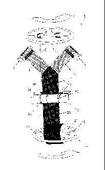
Fig. 1 shows a winder 1, which can be used for the method for continuous
production
of a multiaxial contexture web. In the winder 1, two unwinding rollers 2, 3
are
disposed from which fiber material 4 is unwound and formed into the multiaxial
contexture 5. Thus, the unwinding rollers 2 and 3 are disposed stationary;
this
means that they do not move in space besides rotating about their particular
axes,
so that the fiber material 4 can be unwound. In parallel to the extension of
the
multiaxial contexture 5, two tension elements 6 and 7, which are unwound from
the
rollers 8 and 9 are tautened and used as a delineation of a plane, which is
defined by
the two tension elements 6 and 7. Through a synchronous rotation of the
rollers 8,
9, of a calendering and separation unit 10, and of the windup unit 11, the
tension
elements 6 and 7 rotate about an axis, which extends in parallel and in the
center of
both tension elements 6 and 7.
In the present depiction, the tension element 6 engages the contexture from
behind,
which contexture is unwound from the unwinding roller 2, and the tension
element 7
engages the contexture from the front, which contexture is unwound from the
unwinding roller 3. Thus, the contexture is wound about the plane, which is
defined
by the tension elements 6 and 7. Thus, the fiber material 4 is formed into a
multiaxial contexture 5. Shortly before the multiaxial contexture 5 enters
into the
calendering and separation unit 10, the multiaxial contexture is not yet
solidified.
After passing through the calendering- and separation unit 10, wherein the
calendering- and separation unit 10 comprises two rollers 12 and 13, through
which
the multiaxial contexture 5 is pulled, the multiaxial contexture 5 is
solidified. In the
rollers 12 and 13, there are radial grooves 14, 15, 16 and 17, which receive
the
tension elements 6 and 7. As it is the case in the present embodiment, cutting
blades can be disposed after the calendering behind the output of the two
rollers 12
and 13, which blades separate the tension elements 6 and 7 from the multiaxial
contexture after the exit from the calendering and separation unit 10 with one
cut at
CA 02659555 2009-01-30
the lateral edges. But it is also possible to remove the tension elements
before
calendering and to run the contexture into the calender without tension
elements.
In the present embodiment of a winder 1, the tension elements 6 and 7 are then
wound onto rollers 18 and 19, and in this depiction, the tension elements 6
and 7 are
5 not fed back into the process. However, it is also possible to feed the
tension
elements 6 and 7 back into the process in a circle. The multiaxial contexture
5
becomes a multiaxial contexture 20 after calendering, which is then wound onto
a
roller 21. The rollers 8 and 9, the calendering and separation unit 10 and the
rollers
18, 19 and 21 rotate synchronously, but it is also possible that the rollers
8, 9 the
10 calendering- and separation unit 10 and the rollers 18, 19 and 21 are
held stationary
and the winding rollers 2 and 3 rotate about the axis of the winder 1, wherein
the
fiber material 4 from the winding rollers 2 and 3 is formed into the
multiaxial
contexture 5, wherein the multiaxial contexture 5 is continuously pulled
downward by
the force from the roller 21 and by the force from the rollers 12 and 13, and
pulls the
15 fiber material 4 from the winding rollers 2 and 3.
It is illustrated in Fig. 2, how two webs of a monoaxial contexture 102 and
103 are
wound about a winding plane 104 in order to produce a multiaxial contexture
101,
wherein the winding plane 104 is substantially comprised of the belt drive
105. In the
method according to the invention, the monoaxial contextures 102 and 103 are
20 wound about the side edges 106 and 107 of a tautened belt 108. The belt
108,
which is illustrated in more detail in Fig. 5, is thus tautened about four
drive- and/or
guide rollers 117-120 in a crossover assembly within the winding plane 104.
Thus,
the belt 108 forms protrusions 111-116 at the drive- and/or guide rollers 117-
120.
These protrusions 111 - 116 beyond the guide rollers 117 - 120 cause the
monoaxial
25 contexture 102 and 103 not to come in contact with moving parts during
winding
about the side edges 106 and 107 of the winding plane 104. The belt 108
extends
starting in the upper left corner, namely where the protrusion 115 is provided
at the
roller 20, straight downward in a guide aligned perpendicular to the paper
plane,
namely to the location, where the protrusion 111 is provided at the roller
118. The
roller 118 supports the belt 108 in vertical direction, however, the belt 108
is run
rotated by 180 about the roller 119 in the right upper corner. During the
transition
from the roller 118 to the roller 119, the belt 108 performs a half
counterclockwise
CA 02659555 2009-01-30
26
rotation. This means that the belt edge 109 disposed above the paper plane is
guided on the path from the roller 118 to the roller 119, towards the area
below the
paper plane, where said initially upper belt edge 109 is guided at the roller
119 to a
lower belt edge 109, which is disposed below the paper plane. Simultaneously,
the
edge 110 disposed at the roller 118 below the paper plane is guided towards
the
area above the paper plane at roller 119, when transitioning from roller 118
to roller
119. In the path from the roller 119 to the roller 117, said belt edge 110
extends
above the paper plane with a belt aligned perpendicular to the paper plane.
The rotation is repeated at roller 117 in reverse direction, thus clockwise,
in the path
to the roller 120, so that the belt edge 110 disposed between the roller 119
and 117
above the paper plane is guided to the area below the paper plane in the path
from
the roller 117 to the roller 120, and the belt edge 109 disposed at the roller
117
below the paper plane is guided to the area above the paper plane in the path
from
roller 117 to roller 120.
The belt drive 105 with its belt 108 which is guided so it crosses over itself
is
illustrated in Fig. 3 in a frontal view. It is clearly visible in Fig. 3, how
the belt 108 is
disposed within the winding plane 104 between the rollers 117 and 118, which
are
visible in Fig. 3, so that the protrusions 111 - 114 do not cause the tautened
carbon
fibers to come in contact with moving parts. Furthermore, it can be derived
from Fig.
3, how the belt edge 109, which is disposed in Fig. 2 on the left side of the
figure
above the paper plane, is guided by the crossover guide below the paper plane
in
the right portion of the depiction, and versa, the belt edge 110 is guided
from below
the paper plane in the right portion of Figs. 2 and 3 in the path between
roller 117
and the roller 120 disposed behind the paper plane towards the area above the
paper plane. The belt 108 is configured as a cylindrical belt and does not
comprise
any twisting in itself.
In Fig. 4, the depiction of Fig. 2 is shown in more detail, wherein the
delineation of
the fibers was omitted in order to show the tension rollers 125 and 127, which
protect
the portions of the belt 108 crossing in front of one another from rubbing
onto each
other, since the tension rollers 125 and 127 are disposed between a crossover
point
of the belt 108 and guide the passing components 108 past one another at this
location.
CA 02659555 2013-04-05
27
In Figs. 5.1 and 5.2 an embodiment of a profile belt 121 is illustrated, which
comprises plural profile ridges 122 on the drive side 123, which engage
corresponding ring grooves 129 of drive and/or guide rollers 117 - 120. It is
provided on
the outside 124 of the profile belt 121 in an advantageous embodiment of the
present invention that grooves are provided, which are not drawn in Fig. 5,
and
which are disposed transversal to the drive direction of the profile belt 121,
wherein
the width of said grooves is adapted to the dimension of the width of a fiber.
This
creates an extremely fine transversal groove pattern, which leads to the
particular
fibers of the monoaxial contexture 102, which is wound about the profile belt
121,
being retained by said grooves.
In Fig. 6, a pair of tension rollers is illustrated, which bracket a profile
belt 121
illustrated in Fig. 5, on the drive side and also on the outside, thus
tautening said
profile belt. In Figs. 2 and 3 only tension rollers 125-127 are drawn on the
drive side,
however, it is also possible to use additional tension rollers 130 disposed on
the
outside, instead of two tension rollers 125 and 127, which are only used on
the drive
side, where the profile of said tension rollers comprises a shape
corresponding to the
outside 124 of the belt 121.
In Fig. 7, various belt profiles 131 - 135 are depicted, which can be used for
the
method according to the invention. Thus, this is a profile 131, made of two
semi-
round components with different size, a profile 132 with oval cross section, a
profile
133 with rectangular cross section, a profile 134 with trapezoid cross section
and a
profile 135 with trapezoid cross section, which comprises a triangular ridge
136
towards the drive side.
In Fig. 8, it is illustrated in a front view, how a multiaxial contexture 138
is wound
about a winding plane 137, which comprises convex surfaces 24 on the upper-
and
lower side of the winding plane 137. Hereby, the multiaxial contexture 138 is
run
about the rollers of belt- or band drives 139 and 140, so that the multiaxial
contexture
138 does not come in direct contact with the belt- or band drives. Though,
this
means accepting that the multiaxial contexture is in frictional engagement
with the
convex surfaces, but hereby two simple belt- or band drives can be used, which
do
not require any crossover guide of the belt in the interior of the winding
plane.
Hereby, the configuration of the winding plane 137 is simplified, which makes
the
CA 02659555 2009-01-30
28
method according to the invention simpler to perform and makes the device
according to the invention simpler to produce. Thus, it is necessary in the
winding
plane according to Fig. 8 to use two belt- or band drives, so that the driving
at both
sides or surfaces of the winding plane is oriented in the same direction.
Depending on the side edges of the winding plane or the upper- and lower side
of
the winding plane, having to be equipped by the belt- or band drive, the
dimensions,
in particular the width of the belt, or of the band, are selected. When the
side
surfaces of the winding plane are selected, a belt drive is enough to cover
the side
edges of the winding plane. When the upper- and lower side is equipped by the
belt
drive, it is necessary to resort to a broad band, in order to cover the broad
surfaces
of the winding plane.
Fig. 9 illustrates the winding plane 137 according to Fig. 8, wherein the
dimensions
are selected, so that the upper- and lower side of the winding plane are
provided
with a band drive. Through said winding plane 137, which comprises convex
surfaces 24 at the side edges, a multiaxial contexture 138 can be produced,
wherein
the fibers of the contexture are guided on the large surfaces on the upper-
and lower
side of the winding plane 137. Like in Fig. 8, the particular fibers of the
multiaxial
contexture are moved by the band drives 139 and 140. In this embodiment it is
possible, to run a third monoaxial contexture between the band drives 139 and
140
in order to produce a three layer multiaxial contexture.
Fig. 10 illustrates the end of a plate 201, about which the monoaxial
contextures are
wound, in order to form a multiaxial contexture. The plate 201 thus comprises
side
surfaces 202 and 204, which form a cuboid body together with the upper side
206
and the bottom side 208 of the plate 201, about which cuboid body the
monoaxial
contextures are wound. In an ideal situation, the plate 201 should comprise an
infinitely small plate thickness; however, in reality this is not possible.
Thus, the
plate 201 comprises a cross sectional surface 224, which comprises horizontal
and
vertical extensions. The plate 201 comprises lateral edges 203 and 205, where
a
coil, which is wound about the plate 201, forms winding edges, which cause the
coil
to be configured like a hose with a cross sectional surface, which
approximately
corresponds to the cross sectional surface 224.
CA 02659555 2009-01-30
29
The plate 201 is drawn as a cuboid in dashed lines in Fig. 11, which is
configured by
the lateral surfaces 202 and 204 and the upper side 206 and the lower side
208. In
this body, a wedge 210 is drawn, which forms the inner section lines 214 and
215
with the body drawn in dashed lines, which corresponds to the plate 201.
Relative to
the width of the plate 201, the wedge 210 comprises lateral tetrahedroid
points 211
and 212, which are comprised of one triangular surface 220 each, which are
formed
by the arms 216 and 217 and by the base 218. The wedge 210 in Fig. 11 is
illustrated between the wedge 210 and the end piece of the plate 201 in order
to
emphasize the geometric relationship.
In Fig. 12, the wedge 210 is illustrated by itself, which is defined by the
trapezes 207
and 209, the base area 225, which is identical with the cross section area 224
of the
plate 201, and by the triangular surfaces 220. The trapezes 207 and 209
comprise a
base 218 and sides 221 and 222 disposed opposite to the base 219. The sides
221
and 222 thus have an extension like the width of the plate 201.
In Fig. 13, the wedge 213 is illustrated with a recess 226, whose inner
surface 223 is
shortened relative to the sides 221 and 222 in Fig. 12. The recess 226 can
thus
receive mechanically moving components at the end of the winding table and the
lateral wedges 227 and 228 reach around the mechanically moving components at
the end of the winding table.
In Fig. 14, the wedge 210 is illustrated in conjunction with the plate 201 as
a
coherent body, over which a transparently illustrated coil 245 is placed. The
coil 245
is pulled off from the plate 201 in Fig. 4 from the left to the right and it
is formed into
a contexture 243 by the wedge 210. Thus, the movement direction 229 of the
coil
onto the wedge changes relative to the flow direction 230 and transitions into
the
flow direction 231 of the contexture 243. The entire width of the contexture
243 is
thus widened by the thickness 233 of the plate 201. When forming the coil 245
into
the contexture 243, two respectively folded tongues with the width 232, which
corresponds to half the thickness 233 of the plate 201, are created at the
sides of the
contexture 243.
In Fig. 15, the assembly of Fig. 14 is illustrated again, wherein, however,
the
cascade guide 234, comprised of the wedge 210 and the roller assemblies 235
and
236, is drawn. Besides the additionally drawn roller assemblies 235 and 236, a
lug
CA 02659555 2009-01-30
245 with a bead 246 is drawn, over which the contexture 243 is run. The roller
assemblies 235 and 236 comprise different axes 237, 238 and 239, wherein
particular roller bodies 240, 241 and 242 are disposed on the axes 237 and
238. In
Fig. 15, the roller bodies 240 on the axis 237 of the roller assembly 235 all
comprise
5 a common axis orientation. The particular roller bodies 240 are thus
optionally each
driven by themselves, so that they neither brake nor drive the contexture 243
but
press the contexture 243 onto the lug 246 without force with reference to the
drive
direction. In the roller assembly 236, two additional axes 238 and 239 are
drawn,
wherein the roller body 242 can comprise a slightly different orientation with
10 reference to the axis 239 as well as a slightly different velocity than
the particular
roller bodies 241 on the axle 239.
Fig. 16 shows an assembly comparable to Fig. 15, wherein the particular fibers
244
are illustrated additionally, which form the coil 245 and the contexture 243.
The
function of the cascade guide in Fig. 16 is thus identical to the function of
the
15 cascade guide in Fig. 15, wherein the contexture is illustrated here in
a pronounced
manner, which shows how the coil 245 is formed into the contexture 243 by the
wedge 210.
Fig. 17 shows a sketch of a device in which a multiaxial contexture 301 made
of two
monoaxial contextures 302 and 303 is created. From two storage devices 304 or
20 305, which are provided here in the form of rollers, the monoaxial
contextures 302
and 303 are wound about a winding plane 306 at an angle a, wherein the angle a
is
defined by the side edges 307 and 308 of the winding plane 306 and by the
orientation of the fibers of the monoaxial contextures 302 and 303. In the
method
according to the invention, the two storage devices 304 and 305 rotate about
the
25 winding plane 306 or the winding plane 306 rotates without the two
storage devices
304 and 305 changing their positions. During the winding process, the
multiaxial
contexture 301 is pulled off from the winding plane 306 in pull off direction
310, so
that the multiaxial contexture 301 is formed from the two monoaxial
contextures 302
and 303 in a continuous process. When the winding plane 306 is induced to
30 oscillate mechanically, the contexture on the winding plane 306
comprises a very
small resistance and when the vibration comprises a preferred direction, the
contexture is transported in the pull off direction 310 through the vibration
in the
CA 02659555 2009-01-30
31
preferred direction, so that pulling the multiaxial contexture off by another
device is
not necessary.
Fig. 18 illustrates a time-distance-diagram 312 and a velocity diagram 313
corresponding thereto of a vibration with preferred directions. The time-
distance-
fibers 302, wherein the winding plane 306 illustrated in Fig. 19 performs
vibrations
parallel to the side edges 307 and 308. The vibrations are illustrated in Fig.
19 by
longer arrows against the pull off direction to the left and by shorter arrows
in the pull
off direction to the right. A longer arrow thus represents a higher velocity
and a
movement of the winding plane. This way, the particular fibers of the
monoaxial
contexture 302 are slowly transported to the right in pull off direction 310.
Fig. 20 shows a sketch illustrating the method for producing a multiaxial
contexture
401, in which a multiaxial contexture 402 and 403 from at least one storage
device
CA 02659555 2012-04-03
32
winding plane 406. However, it is also possible that the storage devices 404
and
405 are held stationary, and the winding plane 406 rotates about its
particular
longitudinal axis 407. Besides that, it is also possible that a combined
movement of
the winding plane 406 and the two storage devices 404 and 405 is provided.
During
the relative rotation of the storage devices 404 and 405 and the winding plane
406,
the monoaxial contexture 402 and 403 is placed on one respective side of the
winding plane 406, wherein the monoaxial contexture 402 and 403 uniformly
slides
off the winding plane 406 through the slanted orientation of the longitudinal
axis 407
with respect to the direction of gravity 408, and thus the multiaxial
contexture 401
can be pulled off from the winding plane 406 without the fibers of the
monoaxial
contexture 402 and 403 wedging at the winding plane 406 through static
friction, and
thus cannot be pulled off to form a uniform multiaxial contexture 401.
The scope of the claims should not be limited by the preferred embodiments set
forth
herein, but should be given the broadest interpretation consistent with the
description as
a whole.
CA 02659555 2009-01-30
33
Reference Numerals and Designations
1 winder
2 winding roller
3 winding roller
4 fiber material
5 multiaxial contexture
6 tension element
7 tension element
8 roller
9 roller
10 calendering- and separation unit
11 windup unit
12 roller
13 roller
14 groove
15 groove
16 groove
17 groove
18 roller
19 roller
20 contexture
CA 02659555 2009-01-30
34
21 roller
101 multiaxial contexture
102 monoaxial contexture
103 monoaxial contexture
104 winding plane
105 belt drive
106 side edge
107 side edge
108 belt
110 belt edge
111 protrusion
112 protrusion
113 protrusion
114 protrusion
115 protrusion
116 protrusion
117 drive- / guide roller
118 drive- / guide roller
119 drive- / guide roller
120 drive- / guide roller
121 profile belt
122 profile ridge
CA 02659555 2009-01-30
123 drive side
124 outside
125 tension roller
126 tension roller
5 127 tension roller
128 tension roller
129 ring groove
130 tension roller
131 belt profile
10 132 belt profile
133 belt profile
134 belt profile
135 belt profile
136 ridge
138 multiaxial contexture
139 belt drive
140 belt drive
141 convex surface
20 201 plate
202 side surface
203 edge
204 side surface
CA 02659555 2009-01-30
36
205 edge
206 upper side
207 trapeze
208 lower side
209 trapeze
210 wedge
211 point
212 point
213 wedge
214 section line
215 section line
216 arm
217 arm
218 base (triangle)
219 base (trapeze)
220 triangular area
221 side
222 side
223 area
224 cross sectional area
225 base area
226 indentation
227 wedge
CA 02659555 2009-01-30
37
228 wedge
229 driving direction
230 flow direction
231 flow direction
232 width
233 thickness
234 cascade guide
235 roller assembly
236 roller assembly
237 axis
238 axis
239 axis
240 roller body
241 roller body
242 roller body
243 contexture
244 fiber
245 coil
246 lug
247 bead
301 multiaxial contexture
302 monoaxial contexture
303 monoaxial contexture
CA 02659555 2009-01-30
38
304 storage device
305 storage device
306 winding plane
307 side edge
308 side edge
309 short flank
310 pull off direction
311 long flank
312 time-distance-diagram
313 velocity diagram
401 contexture
402 monoaxial contexture
403 monoaxial contexture
404 storage device
405 storage device
406 winding plane
407 longitudinal axis
408 direction of gravity