Note: Descriptions are shown in the official language in which they were submitted.
CA 02659808 2009-03-24
1
"Fastener with cutting blade for roller printer"
This application claims priority based on European Patent Application
08425211.3 entitled "FASTENER WITH CUTTING BLADE FOR ROLLER
PRINTER" filed March 31, 2008, which is herein incorporated by reference.
In the field of the roller printers with print of vouchers and tickets are
known
opening shutters placed onto the slots from which the paper goes out toward
the
user. These opening shutters are driven by means of an electromechanical
device
that, when necessary, opens the printer shutter from which the voucher or the
printed ticket goes out, to be taken. Said shutters have the aim to avoid that
vandal
acts, like the introduction of different materials or objects inside the
printer slot
from which the vouchers or similar coming out, prevent the coming out of said
vouchers in sequence and so to prevent the correct working of the printer. In
the
known art the devices to print vouchers with roller printers consists of a
cutting
device place downstream of the printing head. In presence of a printer to be
placed in public places or for automatic working, where the user directly
provides
to take the voucher or the ticket, said printer is equipped with two specific
and
different devices: a device for the cutting of the voucher or the ticket to
the paper
roll after that the printing is made and a second shutter device that, in
opening,
permits the getting out of the printed voucher, preventing the introduction of
foreign matters inside the printer. The shutter device is to be opened only to
permit the getting out of the voucher or the ticket and it comes to
immediately
close by means of automatisms and electric motor that drives its working and
they
permit the opening and the closing of the shutter in the scheduled times for
the
working. It is obviously that, to have a cutting device and a opening/closing
shutter device creates high manufacturing industrial costs, so as high are the
costs
determined to the working management of the two devices used in the present
art.
Moreover, the paper blocks up along the shutter way can put out of order the
roller printer with increase of the maintenance costs for the reset. Besides,
the
complexity of the known printers with two different devices determines a
bigger
possibility of breakdowns or jamming of one of the two devices with consequent
impossibility of working of the automating device for printing tickets. Object
of
CA 02659808 2009-03-24
2
the present invention is a shutter for automatic printers, driven by an
electric
motor, to be opened for permitting the ticket getting out and with a blade
integrated in the same shutter. In this way, following to the ticket getting
out from
the automatic printer, the shutter comes to close again and it is able to cut
the final
part of the paper onto which the ticked is printed. To realize a scissors cut,
other
to the shutter with blade is present a counter-blade, mounted onto the frame
of the
printer, in such a way that the ticket in passing onto the two blades is cut.
With the
cutting device integrated into the shutter a minor manufacturing cost and a
minor
complexity of the automatic printer are determined, integrating in a sole
device
the cutting and the opening/closing steps. The invented device, moreover,
permits
energetic saving in the working of the same printer. Others aims and
advantages
of the invention are better pointed out to the following description of a
preferred
but not exclusive embodiment, together with the drawings of the sheets 1, 2
and 3
showing an indicative but not limiting version. In particular in sheet 1
figure 1 is
transversal section view of part of the roller printer with blade closing
shutter. In
sheet 2 figure 2 is frontal view of the shutter provided with upper blade. In
sheet 3
figure 3 is perspective view of an application form of the blade shutter
mounted
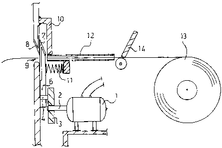
onto an automatic printer for printing tickets. The blade closing shutter for
roller
printer consists of an electric motor 1 with connections to the check and
on/off
card with a shaft 2 connected to an eccentric cam 3 having a pin 4. The pin 4
is
inserted into a hole 5 of a shutter 6, with this shutter 6 having an upper
placed
blade 7 with cutting edge along the direction way of the shutter. In
counterposed
position to the blade 7, fixed onto the frame of the roller printer, is
present an
immovable blade 8 with cutting edge placed on vertical plane not coinciding
with
the plane of the blade 7. Said blades 7 and 8 with counterposed cutting edges
onto
staggered planes are positioned near a slot 9 of getting out of the printing
ticket,
with sizes of the slot 9 such to permit the getting out of the printed ticket
but not
having a space to introduce the fingers inside it. Near the immovable blade 8,
along the inside wall, is present a body 10 suitable to house the shutter 6
with the
blade 7. Said body 10 drives the shutter 6 with the blade 7 and it forms an
anti-
breaking support structure when the shutter 6 with the blade 7 is kept inside
the
CA 02659808 2009-03-24
3
sliding seat by a spring 11, placed between the inside part of the shutter 6
and part
of the printer frame. Moreover, a suitable passage 12 is present, inside which
the
ticket, coming to the paper roll 13, pulled to paper drawing roll and printed
to the
printing head 14, arrives to the opening/closing shutter 6. In working step
the
normal advancing of the paper coming to the paper roll 13 by means of the
paper
drawing roll with print by the head 14 is actuated. The printed paper passes
inside
the suitable passage 12. At the getting out of the printed paper to passage 12
the
control and start devices drive the rotation of the electric motor 1. The
rotation of
the shaft 2 of the electric motor 1, connected with the eccentric cam 3 by
means of
the pin 4, transmits the motion to the shutter 6. Said shutter in closing
position
during the non use step, i.e. in upper position inside the body 10, lowers,
following of the rotation given to the electric motor 1 and with times and
ways
provided to the control device which drives the electric motor 1. Following to
the
rotation of the shaft 2 the eccentric cam 3 reaches the position in where the
pin 4
is in the lower point, permitting to the paper to get out from the passage 12.
At the
end of the printed ticket getting out, in the times and ways provided to the
control
and starting devices of the electric motor 1, the rotation of the shaft 2 is
completed
put again the shutter 6 in the upper position. During the ascent step the
blade 7,
helped in the cutting work to the immovable blade 8, cuts the paper in the end
part
with the print. After to have actuated the cutting of the paper, the shutter 6
with
the blade 7 is in upper position closing the slot 9 from which is got out the
printed
ticked to be put to the user. The closing arranged to the shutter 6 with blade
7, so,
other to actuate the cutting of the printed paper coming the paper roll 13,
prevents
that dust, dirty of other can go into the inside part of the printer damaging
the
head, the paper or other parts inside the printer. The invented device is
possible of
changing and modifications all entering in the present inventive step.
Moreover,
all the technical details are to be changed with equivalent others.