Note: Descriptions are shown in the official language in which they were submitted.
CA 02660011 2013-07-04
ULTRASONIC KNIFE
The present application claims priority under 35 USC 120 to U.S. Patent
Application 11/499,871, filed August 7, 2006.
FIELD OF THE INVENTION
The invention relates to an ultrasonic cutting device that, in a preferred
embodiment,
is used as a cutting device in ophthalmologic surgery. The invention also
pertains to surgical
instruments and techniques comprising the ultrasonic cutting device. In a
preferred
embodiment the surgical instrument is a phacoemulsification ophthalmologic
surgical
instrument and the cutting device is a phaco tip for use in that instrument
which provides a
cutting device that is highly efficient in cutting cataracts into more
manageable fragments.
BACKGROUND OF THE INVENTION
Phacoemulsification is currently the preferred technique used by eye surgeons
for
cataract extraction involving the removal of the cloudy eye crystalline lens.
Through a small
incision in the cornea or the sclera (typically 1.5 to 3.2 mm) the cataractous
crystalline lens is
extracted using a device called a phacoemulsifier and then an artificial
intraocular lens is
implanted. This lens has the function of replacing the crystalline lens, so
that the vision can
be restored to the level it was before the cataract appeared.
An early phacoemulsifier can be seen in US. Pat. No. 3,589,363 (1971) to
Kelman,
that comprises a hand piece connected to a
cylindrical hollow needle, which has a central bore 1.0 to 1.5 mm in diameter
that is
introduced inside the eye through the incision previously made. The needle
vibrates as a
consequence of the ultrasonic energy generated by a source inside the hand
piece (usually
piezoelectric crystals), which converts electricity, into ultrasonic
vibration. The needle
1
CA 02660011 2009-02-04
WO 2008/017909
PCT/1B2007/000358
er0U1SifieS the cataract converting its substance into very small particles
that are aspirated
through its central lumen in a controlled manner. The needle, however, is not
designed for
cutting the nucleus of the cataract or dividing it in several sizable
fragments. Also, as the
needle produces heat while vibrating, it is covered with a sleeve through
which balanced
saline solution is flowing. This fluid cools the needle and replaces the fluid
being withdrawn
from inside the eye, thus avoiding the collapse of the anterior chamber.
The needle involved in many prior art techniques has a cylindrical shape with
a
diameter between 1.0 to 1.5 mm, and thus is not well suited for cutting or
separating the
cataract in sizable fragments, which is the preferred approach taken in modern
phacoemulsification techniques. In an effort to do so, a technique has been
developed which
includes sculpting channels or grooves in the surface of the cataract using
the cylindrical
needle. The grooves must be wider than the needle's diameter so that the
cataract may be
cracked into four segments (the so called divide and conquer nucleofractis).
In order to sculpt
grooves in cataracts of a certain hardness level, there is utilized a high
power of ultrasonic
energy. This has been shown to be able to produce damage to the eye, if
applied for a long
enough period of time. Moreover, even with the application of high ultrasonic
energy levels,
the dividing of a very advanced cataract still may not be possible using the
method of
sculpting grooves, as these cylindrical hollow needles are not really adequate
to divide the
cataract in sizable fragments by themselves. In an effort to avoid the
necessity of sculpting
grooves, other surgical instruments have been designed that use mechanical
energy to divide
the cataract while attempting to save ultrasonic energy. These mechanical
devices include
choppers and pre-choppers. Many models are available (for instance: Nagahara's
chopper
available from Rumex Ophthalmic Surgical Instruments, St. Petersburg, Florida,
USA ¨
Reference: 7-063 TH) and Alcahoshi's pre-chopper (Asico, Westmont, Illinois,
USA ¨
Reference Universal AE-4282)). These devices use mechanical energy to divide
the nucleus.
2
CA 02660011 2013-07-04
However, phaco chop techniques can be More technically difficult, leading to a
greater
likelihood of complications, and, moreover, dividing hard nucleus (brunescent
and black)
cataracts with pre-chopping techniques may be very difficult to master by
surgeons.
Currently there are several phacoemulsification devices available (Infiniti
Vision
System, Akon Inc., Fort Worth ,Texas, USA; Sovereign, Advanced Medical Optics,
Santa
Ana, CA, USA; Millennium, Bausch & Lomb, Rochester, NY, USA) that use
different
pumps and different needles. An example of a phacoemulsification device is
found in U.S.
Pat No. 6,478,766 assigned to Alcon, Inc. (Hunenberg, CH).
The Infiniti System phacoemulsification device of Alcon Inc. , Fort
Worth, TX, USA has the option of using, in addition to the ultrasound sonic
energy, fluid
liquefaction of the cataract to help break down the cataract (e.g., see US
Pat. Nos. 5,616,120
and 6,676,628 also to Alcon ). The newer
phacoemulsification devices also have the capability of modulating the power
of ultrasound
applied. In general the manufacturers have designed them to extract the
cataract after dividing
it into sizable fragments (e.g., four or more) which are then emulsified using
cylindrical
needles.
U.S. Pat. No. 4,504,264 to Kelman,
describes an ophthalmological instrument that features an aspiration needle
that is
longitudinally vibrated as well as laterally oscillated. The lateral
oscillation is described as
working in association with the longitudinal vibration moVement to promote
more-rapid
fragmentation.
= T.T.S. Patent No. 6;592,541 to Kurwa,
describes and ophthalmological device for cutting a nucleus of a cataract with
a phaco tip
having a body with a solid blade with a face edge. The device is used
alternately with a
standard phaco tip (needle with open end) to remove cataracts. As will become
more
3
CA 02660011 2009-02-04
WO 2008/017909
PCT/1B2007/000358
apparent below (e.g., see the Sturnmary of Invention discussion below) the
cutting phaco tip,
has a design that is not efficient in many respects in the cutting and
fragmentizing of the wide
range of cataract types faced.
Due to the limitations as to current phacoemulsification surgical instruments
available, ophthalmologists around the world rely on basically the same
phacoemulsification
surgical technique, with some minor variations. The phacoemulsification
surgical technique
currently relied upon includes the following basic steps:
1. The providing of an access incision which is typically corneal or scleral
with a size
often varying between 1 and 3.2 mm. The incision may be located superiorly (12
or 11
o'clock positions), or completely temporal. Incision architecture may vary.
There may be
utilized single plane, two plane or three plane incisions, depending on the
surgeon's
preference. All of these incisions are intended to be watertight and do not
require sutures to
close.
2. Capsulorhexis is the surgical step where a central circular portion of the
anterior
capsule is removed and it leaves the anterior cortex of the cataract exposed.
In other words
capsulotomy involves creating a continuous tear of the anterior wall to
produce a smooth-
edged round opening. The continuous tear capsulotomy is known as
"capsulorhexis". Such a
capsulotomy facilitates removal of the old lens and also facilitates in-the-
bag implantation of
an intraocular lens. There are.several modes of capsulorhexis forceps and as
some examples
reference is made to U.S. Publication 2004/0116950 Al to Elibschitz ¨
Tsirnhoni and U.S.
Publication 2005/0228419 to El-Mansoury for a discussion of capsulotomy
techniques and
instruments.
3. Hydrodisection is a maneuver by which, using balanced saline solution
injection,
the cortex of the cataract is separated from the capsules, so that the
cataract can rotate inside
the bag.
4
CA 02660011 2009-02-04
WO 2008/017909
PCT/1B2007/000358
4. Hydrodelineation is a maneuver by which, using balanced saline solution,
the
nucleus of the cataract is separated from the most peripheral portion of the
cataract that is
epinucleus and cortex, so that the nucleus can rotate freely.
5. Nuclear pre-fracture is a more recent cataract surgical technique wherein,
before
trying to emulsify a cataract, the nucleus is divided into sizable fragments
by one of several
methods, such as those described above, in order to facilitate its extraction.
As noted above,
since the phacoemulsification cylindrical needles can emulsify and aspirate
just one small
portion of the cataract at a time, and not big portions of the cataract, the
pre-fracture
technique facilitates the complete removal of the cataract material as with a
subsequently
applied cylirxhical phacoemulsification needle. One pre-fracture method
involves sculpting
deep grooves inside the cataract with the phaco needle to provide for the
fragmentation using
the needle, and a second instrument to push the fragments apart. The downside
of this
technique is that it requires more ultrasonic energy, especially in hard and
black cataracts,
and this high energy level requirement can cause damage to the cornea.
Moreover, using this
method sometimes it can be impossible to divide certain very hard cataracts
(like black
cataracts), and it may be necessary to widen the surgical incision to extract
it in one piece
and then suture it, which is undesirable from a post treatment healing
standpoint.
6. Other alternative techniques to divide the cataract before emulsifying it,
is using the
choppers and the prechoppers (like the above described Nagahara's chopper and
Akahoshi's
prechopper), which use mechanical energy. They have the drawback of being
difficult to
learn, taking a long time for the surgeon to master these techniques. Moreover
they have the
risk of rupture of the anterior capsule edge (in the case of choppers) or
zonular stress (in the
case of prechoppers). In very hard nucleus (brtmescent and black cataracts),
these techniques
are not easy to perform, even for the experienced surgeon, since the fragments
do not
separate completely, but their fibers are stretched without breaking.
CA 02660011 2009-02-04
WO 2008/017909
PCT/1B2007/000358
SUMMARY OF THE INVENTION
The subject matter of the present invention includes a cutting device as in an
ultrasonic cutting device designed to cut a cataract in sizable and
manipulatable fragments
with little difficulty, unlike the standard phacoemulsification cylindrical
needles which are
not well suited to easily divide the cataract in that manner. A preferred
embodiment features
an ultrasonic cutting device comprising a shaft, which may be hollow or solid,
and an
opposing side walled "flattened" tip disposed at a distal end of the shaft.
This tip vibrates at
ultrasonic frequency, and is suitable for replacing the mechanical energy used
by choppers
and pre-choppers thus providing for efficient usage of ultrasonic energy. The
ultrasonic knife
of the subject matter of the present invention makes it possible to easily and
efficiently divide
the cataract in as many fragments as the surgeon deems desirable (e.g., 4 to
12). The cutting
device of the present invention provides a tip design that easily and
efficiently cuts through a
. wide assortment of cataract types (e.g., lower energy usage and
associated lowering of heat
generation with less trauma potential). For example, the cutting device of the
present
invention works in softer cataracts like "a hot knife cutting through butter",
and in harder
cataracts (including brunescent and black cataracts) like "a hot knife cutting
through a
chocolate bar".
= The new ophthalmologic cutting device of the present invention provides a
tool which
.pennits a surgeon to improve on the phacoemulsification technique, making it
easier to divide
the cataract into several manipulatable fragments which can then be, for
example, more easily
emulsified with a standard phacoemulsification needle, diminishing the amount
of ultrasonic
energy applied during cataract extraction, and thus reducing the risk of
damage to the cornea.
In addition, the produced fragments can also be more easily liquefied with
technologies that
employ fluid pulses, making the present cutting device even more applicable to
harder
cataracts.
6
CA 02660011 2009-02-04
WO 2008/017909
PCT/1B2007/000358
The cutting device of the present invention thus provides an "ultrachopper"
that
makes for easier performance of a phacoemulsification technique; as in a
phacoemulsification
technique that includes a breaking apart of the cataractous crystalline lens
into more
manageable pieces via the ultrachopper to facilitate completion of the
phacoemulsification
process as by applying a vibrating aspirating needle on the more manageable
pieces created
with the ultrachopper. Another alternative to finish the cataract extraction
following the
fracture with the ultrachopper is using a liquid application tool (e.g., a
heated and pulsing
liquefaction based further breakdown tool) to liquefy and aspirate the
fragments. This
procedure provides a hybrid, phacoemulsification /liquefaction procedure
(which is
categorized under the present invention as a phacoemulsification procedure and
phacoemulsification tooling in general). Thus, with the ultrachopper, surgeons
who are not
highly experienced may learn these techniques in less time and with fewer
complications, and
experienced surgeons may improve even more their outcomes.
The above-described present invention's ultrachopper and its efficient
breakdown or
fragmentation of a cataract into several more manageable or manipulatable
pieces is also
readily incorporated into a variety of cataract removal surgical techniques
and thus also
improves on the cataract removal process in general under those techniques.
For example,
some of the cataract removal surgical techniques involving ultrasonic or
combined sonic-
ultrasonic phacoemulsification and/or liquefaction techniques can utilize the
subject matter of
the present invention and can be categorized into the following "A to C"
surgical techniques,
which removal techniques and associated equipment are considered to fall under
the subject
matter of the present invention:
A) ULTRAPHACO
B) ULTRAQUAL
C) ULTRAMICS
7
CA 02660011 2009-02-04
WO 2008/017909
PCT/1B2007/000358
As an example of the new "ultraphaco" cataract removal technique under the
subject
raatter of the present invention, following or during the course of dividing
the cataract with
the ultrasonic knife or ultrachopper of the present invention (either with
longitudinal phaco
tip oscillation alone or a combination of longitudinal and lateral
oscillation), the fragments
are emulsified using a standard cataract emulsification needle with
ultrasound. The entire
cataract removal technique can be rapidly completed as the ultrachopper not
only rapidly cuts
through even hard cataracts but also separates them, especially when using
oscillatory sonic
or ultrasonic motion and presents broken up cataract pieces to the needle so
that they can be
more readily broken down further and aspirated out through the needle.
As an example of the "ultraquar cataract removal technique under the subject
matter
of the present invention, following or during the course of dividing the
cataract with the
ultrachopper, the fragments are liquefied using fluid fragmentation means as
in a liquefaction
fragmentation means using heated liquid pulses propelled from a tip as in the
liquid pulse
fragmentation "Aqualase" or as in the liquid pulse fragmentation "Infiniti
System" of Alcon =
noted above. The "ultraquar cataract removal technique thus provides for rapid
cataract
removal completion as the ultrachopper not only rapidly completes its
fragmentation
function, but presents fragmented cataract pieces that can be readily further
broken down
with fluid fragmentation means as in the noted "Aqualase "system (or even a
combination of
the further fragmentation techniques described above and below, although use
of just one
further break up of fragmentation (when needed in light of the ultrachopper's
effectiveness in
and of itself) is preferred over multiple supplemental fragmentation from the
standpoint of
rapid completion of the surgical procedure).
As an example of the new "ultramics" cataract removal technique under the
subject
matter of the present invention, following use of the ultrachopper, the
emulsifier means (e.g.,
8
CA 02660011 2009-02-04
WO 2008/017909
PCT/1B2007/000358
needle) of the ultrasonic handpiece or the probe of the Aqualase handpiece is
introduced,
without sleeve, through an incision having a length below 1.5 mm.
Thus, an example of a phacoemulsification technique under the present
invention
includes two main steps: pre-fracture and emulsification of the fragments with
ultrasonic
energy with the ultrachopper representing a phacoemulsification instrument.
Also, while
liquefaction is not generally classified as phacoemulsification, since it uses
liquid pulses
instead of ultrasound, the ultraqual technique is considered a
phacoemulsification technique
by providing a hybrid technique that uses the phacoemulsification ultrachopper
instrument
initially for pre-fracture and then, for instance, the Aqualase probe for
removing the
fragments by liquefaction. Various other arrangements involving pre-fracture
means to
readily break up cataracts into more manageable pieces and removal means for
removing the
results of the pre-fracture means (e.g., further breaking down the manageable
pieces to
facilitate exiting of the material to be removed).
The ultrasonic knife or cutting devices of a preferred embodiment of the
invention
includes a tip having many functions and intrinsic features, having a design
directed at
providing benefits to the surgeon and patient alike. The benefits at which the
present
invention is directed toward include, for example: a lessening of surgical
time, applied
ultrasound energy, and the time required for learning the technique of using
the device.
Additional potential benefits include, for example, faster recovery times for
the patient,
better control ability in the surgeon during phacoemulsification, the making
available of new
techniques of phacoemulsification, and the possibility of implanting
intraocular lenses
through smaller incisions. Also, in a preferred embodiment, the cutting device
is subjected to
the lateral oscillation in addition to the longitudinal vibration to promote
more rapid
fragmentation and separation of the pieces of nuclear material with the
ultrachopper.
9
CA 02660011 2009-02-04
WO 2008/017909
PCT/1B2007/000358
. A preferred embodiment of the present invention includes a cutting
device with a tip
that is distally flattened and made of an efficient ultrasonic energy
transforming material such
as a metal as =in titanium or steel that has an ultrasonic energy transfer
section such as a solid
or hollow shaft (e.g. completely hollow along axial length of the hollow shaft
or hollow over
an. axial portion of the overall length of the shaft). When utilizing a hollow
shaft that has a
larger peripheral area than the distal blade portion of the tip, there is
featured a transition
section where the flattened portion joins with the preferably cylindrical
shaft portion and in
that transition section there is preferably provided an aspiration hole or
holes that are
preferably formed entirely in the transition section and/or partly in the
transition section and
partly in the hollow shaft section. The holes include, for example, either a
superior and/or one
or two lateral (preferably oval) shaped aspiration holes, which provide
aspiration port(s) that
are in fluid (and typically fluid is inclusive of aspirated solids)
communication with an inner
lumen. The lumen formed in the shaft forms part of an overall aspiration
passageway, which
preferably traverses the !haft (e.g., a cylindrical lumen extending in the
fall length of a
cylindrical hollow shaft) and travels within the handpiece sleeve in typical
flow through
fashion.
An alternate embodiment features a solid shaft and a solid transition region
in the area
where the flattened portion joins with the cylindrical portion and thus this
embodiment
preferably does not contain any hole. This alternate embodiment of the
invention has each
one of the flattened portion's "pinched" lateral faces provided with a groove
or grooves (e.g.
two grooves on each flattened face or side wall) in order to diminish friction
when contacting
= the cataract material. There is also, however, featured under the subject
matter of the present
invention, an embodiment of the tip free of cut facilitating grooves. A
preferred embodiment
of the invention also features an angulation of the tip, which preferably
includes an upper
edge having a slope down of about 15 in relation with the horizontal and then
a forward
CA 02660011 2009-02-04
WO 2008/017909
PCT/1B2007/000358
edge assuming an angle, relative to the vertical axis as it extends proximally
back from the
distal most end of the lower blade edge that is preferably about 15 degrees
(e.g. 15 5 ). In
addition, for its preferred usage in breaking up cataracts, the area of
surface of the tip is
preferably about 42 as in from 4.16 mm2 to 4.18 mm2.
In a preferred embodiment there is an irrigation sleeve, which covers the
shaft of the
device, and preferably covers the shaft up to the area where the flattened
portion begins (e.g.,
preferably up to the distal side of the hole in the boundary with the
transition section, leaving
the length of a flattened tip ¨ e.g., 2.5 to 2.6 mm ¨ exposed). This
facilitates the sleeve
covering (i.e., axially extension covering) the superior oval hole, and/or the
lateral holes in
the above-noted aspiration port embodiments. This sleeve-to-port arrangement
helps to
assure that when moving the cutting device backward to place the tip in
contact with the
proximal area of a cataract, the irrigation port or ports located laterally in
the distal portion of
the sleeve do not travel outside the anterior chamber which can disrupt the
surgical
procedure. The length of the distal tip of material contact edge is also
preferably not more
than 3.0 mm (e.g., 2.5rnm to 2.8mm) from the suction orifice which also helps
in avoiding
the irrigation port's suction orifice traveling outside the anterior chamber.
The opposing side walled or flattened portion of the cutting device's tip is
preferably
arranged not only to work as a knife splitting the cataract, but also as a
dissecting spatula,
moving apart the divided portions of the cataract. Also, in embodiments which
have one or
more aspiration holes, the larger diameter of the (preferably oval) hole or
holes is preferably
arranged parallel to the longitudinal axis of the device. Also the flattened
portions of the
cutting device tip are preferably made thinner in the inferior area, than in
the superior one.
Also the ultrasonic energy applied to the tip is preferably applied in two
different manners.
The first manner includes movement of the tip axially in an antero-posterior
motion (i.e., a
longitudinal to and fro movement) the second manner places the tip in or with
an oscillatory
11
CA 02660011 2009-02-04
WO 2008/017909
PCT/1B2007/000358
= motion, with a excursion of, for example, up to 100 as in a 2 to 100
range, with a 2.5 to 5.0
oscillation range being preferable (this added lateral ultrasonic movement
feature is made
possible with some new phacoemulsifiers instruments such as the aforementioned
Infiniti
System of Alcon and which have the possibility of using sonic or ultrasonic
oscillatory
movement with specific handpieces). The oscillatory sonic motion may be
performed
together with the ultrasonic movement or in sequence (either one preceding the
other) or one
without the other depending on the circumstances (e.g. groove formation first
to a sufficient
degree to take advantage of lateral oscillation within the groove thus formed,
followed by any
variety of longitudinal or lateral oscillation applications as the operator
deems best under the
current circumstances). In other words, a means for tip position manipulation
preferably
provides for both antero-posterior motion and oscillatory motion (preferably
the antero-
posterior is utilized first to form an initial cut or groove, and then there
is initiated the lateral
oscillatory movement to help break up the object in the process of being cut --
although a
variety of timing arrangements for the two motions as in simultaneous or
alternating
sequences can be utilized depending on the circumstances faced by the
surgeon). This
arrangement helps in promoting the capability of having the tip simultaneously
cut and move
apart the fragments during the fragmentation process.
A preferred embodiment of the present invention includes a cutting device that
has a
tip with a blade that is thinner at the bottom (initial material contact) edge
and a thicker at
the top edge (a more upper positioned edge relative to the lower edge and
which upper edge
is generally opposite to the lower edge as in one that is parallel or
generally parallel to the
lower edge such as one that is within 10 degrees of being parallel). Having
the upper edge
thicker than the lower edge provides an advantageously oriented wedge shape in
the tip. This
arrangement is unlike, for example, the above described Kurwa reference, which
does not
show a narrowing of cross section in the side walls' spacing. Accordingly,
Kurwa lacks the
12
CA 02660011 2009-02-04
WO 2008/017909
PCT/1B2007/000358
beneficial wedge shape that is provided in a preferred tip embodiment of the
present
invention which wedge shape allows the device to cut through the nuclear
material without
causing excessive stress on the capsular bag and zonular apparatus.
Moreover, a preferred embodiment of the present invention includes the feature
of
having the edge on top of the blade, which preferably extends in straight line
fashion, shorter
than the lower one, which is also a design feature unlike the Kurwa's device.
A shorter upper
edge is an addtional advantageous feature that promotes safety, since when the
blade goes
forward during the cutting of the cataract, the blade portion that first
penetrates the nuclear
material is the longest part of the bottom, and when moving farther forward
this bottom edge
can be displaced under the opposite anterior capsule edge, but since the
superior edge is
shorter there will be some extra space, making the possibility of injuring
this edge, or the iris,
very low.
Another advantageous feature found in a preferred embodiment of -the present
invention, which Kurwa again fails to appreciate, is the angulation of the tip
as in having a
forward edge of the tip slope (curved and/or straight) proximally such as from
the distal most
end as in a tip that is angulated 15 degrees with respect to the horizontal.
This angulation
feature allows the tip to be more easily used. For example, to reach the
nuclear material the
surgeon does not need to tilt the device too much. Moreover this angulation
feature can
increase the cutting device's safety, because the possibility of injuring the
anterior capsule
edge in the area located opposite to the incision is significantly reduced.
BRIEF DESCRIPTION OF THE DRAWINGS
Other features and technical advantages of the present invention will become
more
apparent from a study of the following description and the accompanying
drawings, in which:
13
CA 02660011 2009-02-04
WO 2008/017909
PCT/1B2007/000358
= _ -
uuu J 0
Figure 1 shows a partially cut away view of an ophthalmologic surgical
instrument with
= cutting device having an aspiration passage in the cutting device's
shaft.
Figure 2 shows an alternate embodiment of the surgical instrument in Figure 1
with a solid or
non-axial aspirating cutting device shaft.
Figure 3 shows a perspective view of the cutting device shown installed in the
surgical
instrument of Figure 1.
Figure 3A shows a partial top (or superior) plan view of the cutting device
shown in Figure
3.
Figure 3B shows a partial bottom (or inferior) perspective view of the cutting
device shown
in figure 3
Figure 4 shows a partial perspective view of the distal end of the cutting
device shown in
Figure 3.
= Figure 5 shows a partial perspective view of the cutting device shown in
Figure 2.
Figure 6 shows a modified embodiment of the cutting device with aspiration
port shown in
Figure 4, with the Figure 6 embodiment being free of grooved side walls.
Figure 6A shows a vertical bi-sect of the tip shown in Figure 6.
Figure 7 shows a modified embodiment of the cutting device shown in Figure 5,
with the
Figure 7 embodiment being free of grooved side walls.
Figure 8 shows a side elevational view of that which is shown in Figure 4.
Figure 8A shows an enlarged, cut-away view of the distalmost region of the tip
shown in
Figure 8.
Figure 9 shows an alternate embodiment of the cutting device which is free of
side wall
grooves and has side aspiration ports in place of the superior or upper edge
aspiration port
shown in Figure 6.
= 14
CA 02660011 2009-02-04
WO 2008/017909
PCT/1B2007/000358
Figure 10 shows a view similar to Figure 9 but for an embodiment inclusive of
side wall
grooves
Figure 11 shows a cut-away view of the cutting device in Figure 10 taken along
cross section
line XI-XI in Figure 10.
Figure 12 shows a partially cut away view of the ophthalmologic surgical
instrument similar
to that shown in Figure 1 but having mounted therein an alternate embodiment
of the present
invention's cutting device which is an embodiment having an extended flat
bottom edge free
of' a recess as in the bottom edge of Figure 1 which is inclusive of a curved
recess in its
bottom, material contact edge.
Figure 13 shows a view similar to Figure 12 but for an alternate embodiment of
the cutting
device featuring a solid cutting device shaft.
Figure 14 shows a superior perspective view of the distal end of the cutting
device shown in
= Figure 12.
Figure 15 shows another perspective view of the cutting device shown in Figure
12.
Figure 16 shows a modified embodiment of the cutting device shown in Figure
15, but with
the Figure 16 embodiment being free of grooved side walls.
Figure 17 shows a perspective view of the cutting device shown in Figure 13
Figure 18 shows a modified embodiment of the cutting device shown in Figure 17
but with
the Figure 18 embodiment being free of grooved side walls.
Figure 19 shows a side elevational view of that which is shown in Figure 15.
Figure 20 shows an alternate embodiment of the cutting device with side
aspiration ports in
place of the upper edge aspiration port shown in Figure 15 with Figure 20
being inclusive of
side wall grooves.
Figure 21 shows a view similar to Figure 20 but for an embodiment free of side
wall
grooves.
CA 02660011 2009-02-04
WO 2008/017909
PCT/1B2007/000358
ligUre 22 shows a front view of the cutting device shown in Figure 20.
Figure 23 shows a perspective view of a third embodiment of the present
invention.
Figure 24 shows a side elevational view of that which is shown in Figure 23.
Figure 25 shows a vertical bi-sect of that which is shown in Figure 24.
Figure 25A shows an enlarged view of the circled portion of Figure 25,
Figure 26 shows a superior plan view of distal region of the cutter device
shown in Figure
24.
Figures 27A to 27Q show a preferred sequence for cutting a cataract with the
cutting device
of Figure 1 with a supplemental flat tip fragmentation facilitator tool.
Figures 28A to 28C show a set of supplemental tools (fragmentation facilitator
tool (Fig.
28A), microspoon tool (Fig. 28B), and nucleus sustainer tool (Fig. 28C)) which
can be used,
individually, alternatively alone or in the possible groupings and sub-
groupings, in
conjunction with the cutting device of the present invention.
Figure 29 shows a closer view of the fragmentation facilitator tool shown in
the Figure 28
set.
Figure 30 shows a closer view of the nucleus sustainer tool shown in the
Figure 28 set.
Figure 31 shows a closer view of the microspoon tool shown in the Figure 28
set.
Figure 32 and 32A to 32C show the cutting device of Figure 10 and its movement
when
connected to a driving means that provides an oscillating motion in a
direction transverse to a
superior to inferior bi-section of the blade.
Figures 33A to 33F show a preferred sequence for cataract cutting using the
cutting device
of Figure 1 with a supplemental nucleus sustainer tool.
DETAILED DESCRIPTION OF PREFERRED EMBODIMENTS OF THE
INVENTION
16
CA 02660011 2009-02-04
WO 2008/017909
PCT/1B2007/000358
The aforementioned Figures are illustrative of a plurality of preferred
embodiments,
although the present invention is not intended to be limited to those
embodiments. The
illustrated embodiments are inclusive of embodiments having planar side walled
configured
distal tip blades providing a "flattened" (in appearance ¨as the distal blade
can be formed or
manufactured in a variety of ways such as molding, machining or material
manipulation
forming, etc) tipped cutting device. The illustrated embodiments also depict
two different
types of (preferably cylindrical) shafts, one hollow and the other solid
amongst the various
embodiments depicted. When attached to a hollow shaft or barrel, the flattened
tips
preferably have apertures as in one or more aspiration holes (e.g., one or
more (preferably
one) upper edge holes and/or one or more (preferably two opposite) side
aspiration holes),
with the illustrated embodiments depicting one and two holes, respectively, in
communication with the bore of a hollow shaft.
Embodiments of the essentially planar, opposing side walled or "flattened"
phaco tips
of the present invention feature embodiments with grooves in their lateral
surfaces as well as
embodiments free of such grooves. The embodiments shown in the Figures also
show
different tip designs with a phaco tip such as that shown in Figures 4 to 11
being well suited
for cutting through hard or very hard (brunescent and black) cataracts
(although this tip
design is also efficient in use with other characteristic cataracts including
soft and medium
density or hardness cataracts). The embodiment depicted in Figures 15 to 19
and the
embodiment illustrated in Figures 23 to 26 are well suited for use with the
soft to medium
hardness cataracts, although the Figure 15 embodiment and Figure 23 embodiment
are also
suited for use with harder cataracts, although deemed less efficient relative
to the Figure 4
embodiment. The opposite can also be said in that an embodiment such as that
in Figure 4,
while being designed for use with harder cataracts, is also suited for use
with softer cataracts,
17
CA 02660011 2009-02-04
WO 2008/017909
PCT/1B2007/000358
albeit in a manner considered less efficient than the Figure 15 and Figure 23
embodiment
relative to softer cataract material.
With reference to Figure 1, there is.shown a partially cut away view of a
surgical
instrument in the form of a phacoemulsification ophthalmologic surgical
instrument 20.
Instrument 20 includes a cutting device 22 (also referenced below as a knife,
chopper and
"ultrachopper"). In the embodiment shown in Figure 1 and corresponding Figures
3, 3A, 3B,
and 4, cutting device 22 comprises ultrasonic energy transmission section 24
and tip 26.
Transmission section 24 preferably extends between the proximal end 76 of tip
26 and the
proximal end 27 of cutting device 22. Tip 26 is shown as comprising transition
section 40
and blade 28 with the blade having distally positioned, opposing (generally)
planar side walls
34 and 36 that together provide a "flattened," "material contact" portion in
the cutting device
22. Transition section 40 extends from the distal most end 76 of energy
transmission section
24 to the proximal most end 64 of blade 28.
= In a preferred embodiment, energy transmission section 24 includes shaft
46 (Figure
1 featuring a hollow or internalized aspirating passageway embodiment, and
Figure 2
featuring a solid shaft or non-aspirating embodiment 46') as well as connector
48 ( or means
for attachment) to a movement generator (schematically shown at 29 which is
preferably in
= the form of an ultrasonic vibrating device such as one utilizing a
piezoelectric transducer,
although alternate movement generating devices are also featured under the
present invention
including, for example, alone or in conjunction with one or the other, fluid,
acoustic, motor
(e.g., offset cam) , reciprocating piston or other movement generating means.
In a preferred embodiment shaft 46 includes a cylindrical shaft segment 60
that is
preferably approximately 14 nnn in length and 1 mm in diameter, although a
variety of
alternate cross-sectioned shaped, preferably straight shaft segments and
lengths are featured
under the subject matter of the present invention. Shaft segment 60 can be
hollow or solid,
18
CA 02660011 2009-02-04
WO 2008/017909
PCT/1B2007/000358
according to the model of the device, with Figure 1 showing an embodiment that
is hollow
laving axially extending lumen 58 forming part of an aspiration passageway 61
and with
lumen 58 preferably having an internal surface diameter between 0.8 to 0.9 mm.
Figure 2, on
the other hand, shows a solid shaft segment 60 and thus is free, at least
internally, of an
aspiration passageway. Between the proximal end =62 of shaft segment 60 and
proximal end
27 of cutting device 22 there is provided transition (preferably cone shaped)
segment 68,
which is preferably about 8 mm in length (e.g., 8.02 mm length) with an
inclination in
relation to the horizontal axis of about 3 to 5 degrees (e.g., approximately
3.6 degrees) and
preferably has a narrow distal diameter end (e.g., 1 mm) and a wider proximal
end (e.g., 2
rum). Also, between those two end points is also found flange disk 52 (e.g.,
one that is about
= 2.5 mm (e.g., 2.62 mm) in diameter and with a width of approximate 0.5
mm) sandwiched
between threaded cylindrical male projection tube 50 and square head 54 (e.g.,
a square of
approximate 2 x 2 mm and 1 mm in thickness). It should be noted that all
dimensions
provided above and below throughout this application are not intended to be
limiting, but of
assistance in illustrating some of the possible characteristics of some of the
embodiments of
the invention including dimensions that, for example, are well suited for a
surgeon
positioning and utilizing the surgical instrument of the present invention
within the limited
space eye environment involved as well as .providing a cutting device that is
readily
attachable to preexising movement generators and irrigation systems. For
instance, the
threaded male connection tube 50 and step down conical shaft 68 features
described above
are also present in standard models of phacoemulsification devices and thus
the cutting
device 22 of the present invention is well-suited for ready replacement of
prior art cutting
devices designed for securement to standard phacoemulsification handpieces
such as that
represented by housing 114. In other words, the illustrated male connection
tube 50 with
standard threaded proximal three thread rings on a supporting cylinder of
approximately 2
19
CA 02660011 2009-02-04
WO 2008/017909
PCT/1B2007/000358
t1111 in diameter and 4.65 mm in length is adapted for attachment to an.y one
of a variety of
phacoemulsification handpieces, many of which utilize a piezoelectric
vibration source such
as vibration source 29. In addition, when irrigation fluid circulation is
desired to help cool the
vibrating cutting device and/or provide fluid circulation within the surgical
area of the eye,
there is preferably provided sleeve 112, which is typically formed of a
medical grade silicone
and has a proximal sleeve segment 115 with threaded connection with housing
114 and fluid
seal 116. Sleeve 112 also preferably has a step down conical transition zone
117 between the
larger cylindrical proximal segment 115 and shaft sleeve segment 118. Sleeve
segment 118
has distal end 120 (a distal irrigation flow end when fluid is flowing in
sleeve 112) with an
interior surface just slightly larger in diameter (e.g., 0.2 to 0.5 mm larger)
in order to maintain
an open irrigation radial space along shaft segment 60 relative to the axially
corresponding
exterior portion of shaft 46 for irrigation flow control out of the space
between the distal end
120 of sleeve segment 118 and the tmderlying preferably tapering tip
transition section 40 of
tip 26.
Sleeve segment 115 has a larger interior diameter than =the interior
positioned cutting
device and thus there is formed annular space 122 between the sleeve end
portion 115 and
shaft 46. Fluid inflow is provided within space 122 in the illustrated
embodiment such that
irrigation fluid circulates within and through annular space 122 as well as at
the annular space
formed between the sleeve's distal end 120 of sleeve segment 118 and the
axially
corresponding exterior portion of transition section 40 preferably at least
partly covered over
by sleeve segment 118.
With reference to Figures 4 there is illustrated aspiration port 90 which is
used with
the hollow version of shaft 46 shown in Figure 1. Aspiration port 90 is in
fluid
communication with lumen 58 of aspiration passageway 61 with the straight
lumen section
58 shown extending within cylindrical shaft segment 60 as well as within the
conical
CA 02660011 2009-02-04
WO 2008/017909
PCT/1B2007/000358
transition section 68 of shaft 46 Lumen 58 of aspiration passageway 61. also
feeds into
diverging passage section 63 of aspiration passageway 61 and then into
enlarged diameter
proximal passage section 65 of aspiration passageway extending within the
handpiece or
housing 114 of the phacoemulsification instrument. As seen from Figure 1,
aspiration port 90
is positioned so as to have its distal end 100 axially proximal relative to
distal sleeve end 120
(e.g. preferably a distance D of less than lmm with 0.15 to 0.3 mm there
between being
preferable with Figure 3A not drawn to scale in this respect). As also seen
from Figure 4,
aspiration port 90 extends axially (longitudinally) to opposite axial sides of
border line 76
representing a boundary line between the sloped transition section 40 and the
shaft 46. In this
way, there is a scoop effect (a radial inward sloping deviation in a
percentage of the
aspiration port outer boundary wall forward of the boundary line 76 (e.g. 20
to 25% of the
whole axial length of port 90 is forward of boundary line 76) ) due to the
aspiration port's
outer boundary wall and interior boundary wall conforming to the slope of
convergence in
exterior surface 66 of transition section 40 (e.g., a slope of 65 to 70
degrees from the
horizontal).
Aspiration hole or port 90 is shown positioned at a superior or upper edge in
use
position relative to shaft 46 and is preferably more elongated in the axial
direction of
extension along the major axis 92 of the instrument than in a lateral
direction transverse
thereto along minor axis 94 with an oval or elliptical shape being preferred.
A ratio difference
of 1.5/1 to 4/1 (e.g. 2/1) relative to axial length/lateral width is
preferred, with a preferred
embodiment having a 0.4 to 1.0 mm length (e.g. a length of 0.6 mm length and
0.3 mm
width), with rounded ends which have a radius of curvature of about 0.15 nun.
Also, as
shown in Figure 4 and 6A port 90 is preferably comprised of exterior
aspiration port
boundary edge 98 and a sloped wall 99 extending radially inward to an interior
boundary
edge 100. The slope of wall 99 is preferably in a common direction both at the
proximal and
21
CA 02660011 2009-02-04
WO 2008/017909
PCT/1B2007/000358
distal end of the aperture port 90. An example of this can be seen in the
cross-sectional view
of Figure 6A showing parallel line segments 99A and 99B for wall 99 which
provides for
enhanced emulsification outflow as the distal to proximal sloping wall
arrangement that
opens directly into lumen 58 of shaft segment 60. A slope of 30 to 60 is
preferred with
45 slope being suitable for many uses. Aspiration port 90 thus provides for
fluid
recirculation access from the surgical region of the eye with that eye region
being fed with
fluid via the irrigation outlet at the distal end 120 of sleeve 112. Thus the
superior positioned
aspiration port 90 is in fluid communication with the lumen 58 of the hollow
cylindrical shaft
46, and port 90 thus provides for the aspiration of fluids and also some
debris originated
when cutting and emulsifying a cataract. A preferred axial location for the
distal end of
aspiration hole from the distal most point 30 of tip 26 is about 2.2 to 2.8 mm
with about 2.65
min 0.5 mm being preferred. The distal end of sleeve 120 when present is
thus about 2.7
to 2.9 mm from the distal most end of tip 26 with 2.8mm .25mm being preferred.
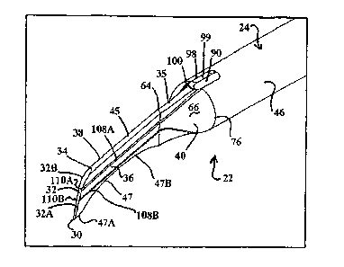
Figure 3 shows cutting device 22 in perspective including its tip 26 with
blade section
28 and transition section 40. In Figures 3, 3A, 3B, 4 transition section 40 is
shown as having
pinched, axially converging (curved in elevation) side transition walls 37, 39
leading distally
to the blade 28 and having superior upper transition edge or ridge 35 and a
similar configured
inferior transition ridge 41, with the superior transition ridge 35 having a
rounded off cross
section to correspond with the rounded off cross-section in upper edge 45 of
blade 26. Figure
3 also depicts in perspective ultrasonic energy transition section 24 having
threaded
projection tube 50, flange disk 52, square head 54 and shaft 46 comprising
cone-shaped
segment 68 and cylindrical shaft segment 60.
Figures 3A, 3B, 4, 5, 8 and 8A illustrate in greater detail an embodiment of
tip 26
which provides a phaco tip for cutting through a cataract which is
particularly well suited for
cutting through harder cataracts such as black and brunescent cataracts. As
seen, blade
22
CA 02660011 2009-02-04
WO 2008/017909
PCT/1B2007/000358
section 28 has opposing, generally planar side walls 36 and 38 extend from a
thicker upper
edge 45 to a lower thinner width edge 47 (with edge 47 being "sharper" but is
as shown in
Fig. 3B still preferably rounded off in cross section in, for example, the
straight, material
contact lower edging portions in edge section 47A to help avoid iris damage.
This inferior
edge can also represent a non-rounded edge as in a vertex line edge or a flat
bottom edge with
sharp angle side wall extensions, but the advantage of being rounded lies in
less potential for
damaging the iris or the anterior capsule during the instrument insertion into
the eye,
although during the cutting action itself the edging is not of concern for
causing eye damage.
Thus, for the additional benefit of damage avoidance during the insertion and
removal from
an incision, a preferred embodiment features a concave profile (e.g., that
shown in 47B, Fig
5), although the alternate edge configuration also form part of the subject
matter of the
present invention.
=
Upper edge 45 preferably has a thickness of about 1.5 to 5 times that of the
lower
sharper edge 47 with a range of 0.4 mm to 0.9 mm being preferable for upper
edge 45 and 0.2
to 0.5 mm (e.g. .3 or .4 mm) for lower edge 47. Thus blade 28 has a ship's
keel configuration
(at least at the distal end relative to the hook-shaped blade in the Figure 1
embodiment blade
and fully for the Figure 2 embodiment which is described in greater detail
below). Blade 28
includes an inferior, material contact point 30 representing the distal most
point on the blade,
and hence also that of the cutter 22. Extending upward and sloping in a distal
to proximal
direction from point 30 is superior forward edge 34 of blade 26 which forward
edge goes
from a thicker upper end to a thinner bottom end as it conforms with the
converging side
walls 36 and 38. Forward edge 32 is shown in,the Figures as extending from
inferior material
contact point 30 and then proximally back toward the shaft until it reaches
superior upper end
point 34. Forward edge 32 is also shown as a curving edge with a preferred
arrangement
being one where there is a straight line slope forward edge section 32A
transitioning into a
23
CA 02660011 2009-02-04
WO 2008/017909
PCT/1B2007/000358
carved upper forward edge section 32B. Proximal end point 34 for forward edge
32 also
coincides with the distal end for upper edge 45, while the opposite end of
edge 45 is
represented by boundary line 64 (Fig. 8) at the distal end of transition
section 40. Figure 8
also shows downwardly sloping upper edge 45 sloping downward from the
horizontal by
angle Al which is preferably from 5 to 30 and more preferably about 15
(e.g., 15 5 ),
Figures 8, 8A and 3B also provide a view of the blade's lower edge 47
featuring
straight section 47A and a recessed (preferably curved as in a concave curve)
section 47B.
End point 30 represents the vertex for angles A2 and A3 shown in Figures 8 and
8A. Angle
A2 represents the angle that the inferior segment 32A of forward edge 32
slopes proximally
from the vertical. An angle of 15 to 45 is preferred with an angle of about
15 to 30 5
being well suited for use under the invention, with 15 5 being preferred.
Angle A3
represents the slope upward off the horizontal that lower edge segment 47A
assumes which is
preferably about 5 to 30 with an angle of about 15 5 being well suited
for the purposes
of this invention. In a preferred embodiment the upper edge 45 and the lower
edge extend in
parallel fashion or in generally parallel fashion as in within 10 of being
parallel (e.g. a 5 or
less offset form a parallel orientation).
Forward edge 32 is shown to have convex curving segment 32B extending
proximally
away from inferior segment 32A. Segment 32B provides a rounded transition
upper comer
between segment 32A .and edge 45. This curved segment 32B preferably has a
radius of
curvature of between 1.0 and 2.0 mm with 1.25 1 .2 mm being preferred. The
overall length
of forward edge 32 is about 2.0mm .5mm with the overall vertical height
between points 30
and 32 preferably being about .75 to 2.0 mm with 1.0 mm .2inm being
preferred. Also, the
relative % of segments 32A and 32B relative to the overall length of forward
edge 32 is
preferably about 60% 10% in edge 32A and 40% 10% in curved edge 32B.
= 24
CA 02660011 2009-02-04
WO 2008/017909
PCT/1B2007/000358
The convergence of side walls 36 and 38, in going down from upper edge 45 to
lower
edge 47 has angle B1 (shown in Figure 3B for this embodiment and in Figure 22
for an
alternate embodiment) but which angle is preferably about 5 to 10 wide with
7 1 being
preferred. Each of upper edge 45 and lower edge 47 can maintain a constant
thickness value
in going proximally away from the distal end along the longitudinal or axial
direction of the
instrument. However, in a preferred embodiment in addition to the above
described vertical
convergence in walls 36 and 38 there is preferably provided in those side
walls 36 and 38 a
minor degree of divergence in extending longitudinally away from the distal
end of the
cutting device (with the width of the upper and lower edges 45 and 47 also
diverging along
the longitudinal with the side walls in similar fashion to the convergence of
the forward edge
32 relative to the convergence of the side walls in the vertical). The degree
of divergence in
the upper and lower edges 45 and 47 is preferably a relatively minor
divergence angle in the
axial direction (with a distal to proximal divergence of, for example, 3 to 4
and more
preferably about 3.5 ) which helps the blade provide a separation effect to
promote
fragmentation breakaway. For example, starting with the above maintained
forward edge 32
defined upper and lower edge thickness levels, a slight expansion in going in
the proximal
direction is provided. For instance, the lower edge section preferably
diverges in the distal to
proximal direction from a thinnest point 30 located at the distal end of lower
edge 47.
Preferably the lower non-curved section 47A has a minimum thickness of about
0.3mm at the
distal end point 30 and then slightly diverges outward over its length and
then a continued
divergence is provided in the more proximal section 47B. Also, the boundary
edge between
sections 47A and 47B of lower edge 47 is preferably represented by a rounded
off comer (to
avoid iris and anterior capsule damage) although a non-rounded off comer at
this location is
also featured under the present invention. The divergence of lower edge 47 is
preferably such
that it goes from the minimum distal thickness of 0.3 mm to a thicker proximal
end thickness
CA 02660011 2009-02-04
WO 2008/017909
PCT/1B2007/000358
which is preferably of a lateral thickness greater than 0.4 mm as in 0.5 to
0.7 mm in lateral
thickness. An alternate embodiment includes having edge segment 47A of a
constant thin
thickness in the axial direction and then lower edge 47 expanding out as
described above
starting with the segment 47B. Also, the recessed portion of section 47B
preferably extends
over the entire distance between the proximal end of section 47A to the distal
end of
transition section 40.
As shown in Figure 4, the upper edge 45 (and continuing on with ridge 35) also
preferably diverges outward in going from the distal to proximal direction,
with the
expansion preferably originating at the upper end point 32B and continuing on
to the
transition section border 76 (e.g., a distal thickness of 0.4 mm at end 32B to
a proximal
thickness of 0.9 mm at the aspiration port 90 region).
By providing a thinner, "sharp" (e.g. relatively sharp but preferably having
rounded
edging in the width direction or in going between the sidewalls) edge distal
blade segment
there is an initial reduction in cataract cutting resistance while the tip
design also provides for
highly effective transmission of ultrasonic energy to the tip. Bottom edge
section 47A
continues directly from the end of recessed bottom blade section 47B up to
distal most point
= 30 and is preferably straight and ends at a sharp point at 30 with the
assistance of the straight
edge portion 32A of forward edge 32. Its longitudinal (proximal to distal)
length is
preferably between 0.1 mm and 0.4mm with a 0.15 mm 0.04 mm being preferred.
Its
thickness preferably is from 0.03 to* 0.3mm to give a sharp edge feature.
Concave lower edge segment 47B preferably has a radius greater than that of
radius
R1 of forward edge segment 32B with Figure 8 showing a curative radius R2
which is
preferably 1.75 to 2.5 mm with 2.0 mm .2 mm being preferred. This recessed
region 47B
in the lower blade edge segment 47B facilitates the avoidance of non-desirable
iris or other
eye segment inadvertent contact when the cutting device 22 is displaced
backward.
26
CA 02660011 2009-02-04
WO 2008/017909
PCT/1B2007/000358
Also as seen from Figures 8 and 8A, the point 30 is distally further
positioned along
the axial length of cutting device 22 than point 34 representing the border
line between the
more sloping forward edge 32 and the less sloping upper edge 45. Thus the
overall top edge
is shorter than the overall bottom edge of the cutting devices blade 26 along
a straight line.
This provides for a cutting process wherein, when the blade goes forward, the
blade part what
must penetrate the cataract (e.g. a cataract nucleus) first is the longest
bottom part while the
shorter upper part is shaped to avoid harming the iris on the top edge of the
capsule during
the cutter movement along the cataract. Figures 8A illustrates this difference
via reference
"D1" which extends axially between the farthest distal lower edge point 30 and
the farthest
distal upper edge point 34 between which forward edge 32 extends (in view of
the
uninterrupted edging of both the forward edge 32 and the upper edge 45, the
upper edge point
34 is preferably that portion of the total superior edging (extending
proximally off from point
30 and distally from the distal end of the transition section) that represents
a boundary point
between a more vertical or about equal vertical rise section as compared to
the longitudinal
rise of that total superior edging (as represented by forward edge 32) and the
less vertically
rising section of that total superior edging (as represented by upper edge 45)
. Alternatively,
point 32B can be considered the demarcation point wherein there is an
initiation of an
increase in the degree of downward slope as compared to a region constituting
either a less
sloping or non-sloping upper edge region of the blade (if both less sloping
and non-sloping
upper edge regions are proximal to the demarcation point than whichever is the
more distal is
the comparison frame of reference). In a preferred embodiment this difference
D1 is about
0.35 to 0.5 with 0.45 mm .05mm being preferred.
Figure 1 also represents an embodiment of blade 28 that is inclusive of side
wall
grooving which facilitates the dividing of the cataract nucleus with less
ultrasonic energy
output and a reduction in resistance to cut formation, particularly with
respect to harder
27
CA 02660011 2009-02-04
WO 2008/017909
PCT/1B2007/000358
cataracts that are more likely to have hard enough material to span the thin-
grooves rather
than be compressed into the grooves. As seen from Figures 4 and 8, the blade
26
embodiment of the present invention includes a plurality of grooves or
serrations formed in
the side walls of the blade with there preferably being a plurality of
vertically space apart
grooves on each side wall (e.g., two on each side wall spaced vertically apart
form each other
and from their respective closest upper and lower edges of the blade). Figures
4, 5, and 8
illustrate a pair of grooves 108A and 108B on side wall 36 and a pair of
grooves 110A
andl 10B on the opposite side wall 38. The grooves within a pair preferably
extend parallel
to one another along the flattened blade portion and then follow the curved
exterior surface at
the same height level in traveling back to boundary edge 76 at shaft 46. The
upper and lower
positioned grooves on side wall 36 also preferably are at a common height
level with the
respective upper and lower grooves on opposite wall 38. Both the depth and
vertical width of
the grooves 108A, 108B, 110A, 101B is preferably less than .1 mm with examples
being 0.05
mm .025 mm for the depth and 0.06mm 0.025 for the vertical width. Upper
grooves
108A and 110A are preferably positioned within the upper 1/2 of the maximum
vertical height
of blade 28 with a preferred embodiment placing the upper groove around the
1/3 mark as in
0.3mm down from upper edge 45 for a 1.0 mm maximum vertical height blade 26.
The
grooves preferably have a consistent depth and height along their full axial
length. Also, the
lower set of grooves 110B and 1120B on each side wall preferably have the same
dimensions
as the upper groove while being positioned within the lower half of the
vertical height of
blade 26 with about a 2/3 down position point from the upper edge being
preferred as in a
= 0.6mm down from the upper edge 45 positioning for a 1.0 mm height blade.
Also the axial
length preference for transition 'section 40 comprising an aspiration port or
multiple aspiration
ports is preferably about the same as the vertical height of blade 26 as in a
1.0 mm axial
length in transition section 40.
28
CA 02660011 2009-02-04
WO 2008/017909
PCT/1B2007/000358
Figure 5 shows cutting device 222 which has a tip 126 similar in all respects
to tip 26
including a common blade 28= design as shown in Figure 4, but tip 126
comprises a modified
transition section =140 and a modified shaft section 46' with both being a
solid mass free of
any internal aspiration passageways. Thus there is no internal aspiration
carried out with
cutting device 222 in Figure 5.
Figure 6 shows an alternate embodiment cutting device 322 with its tip 226
including
a generally similar design as to tip 26 in Figure 4, but for its blade 128
being different than
blade 28. That is, blade 128 has the same configuration as blade 28 in Figure
4, but the
opposing walls 36 and 38 are free of any grooving along their surface so as to
present
uninterrupted smooth surfacing on each of side walls 36 and 38, as well as
preferably their
corresponding transition walls 37 and 39 as border line 64 preferably
represents a smooth
(large radiuses) fillet type transition.
Figure 7 shows an alternate embodiment of cutting device referenced as 422 and
. having tip 326 with a similar blade 128 as in Figure 6, but cutting
device 422 features a solid
shaft 146 and transition region 140 and free of any aspiration ports (e.g.,
the small amount of
debris of material originated during the fragmentation can flow out of the eye
with the fluid
outflow through the incisions).
Figure 9 shows an alternate embodiment cutting device 522 having tip 426 which
is
similar in all respects to cutting device 322, but for a modification in the
aspiration hole
arrangement distal of the shaft 46. In Figure 9, rather than having a superior
edge positioned
aspiration port, there is provided aspiration porting in transition walls 37
and/or 39. Each
aspiration hole 90A and 90B provided in the transition section 40 (e.g. within
the
intermediate region 25% to 75% of the overall axial length of transition
section 90)
communicates with lumen 58 provided within hollow shaft 46.
29
CA 02660011 2009-02-04
WO 2008/017909
PCT/1B2007/000358
Figure 10 shows an alternate embodiment cutting device 622 with tip 526 with
the
= latter having a blade section similar to blade 26 in Figure 1, but a
transition section 240
similar to that in Figure 9 in that it includes ports 90A and 90B.
Figure 11 provides a cross-sectioned new taken along cross-section line XI ¨
XI in
Figure 10 showing aspiration opening 90A and 90B former in the sloping
exterior surfaces
of transition walls 72 and 74 and communication with aspiration conduits P1
and P2
extending through the thickened region of transition section 240 until opening
out at the distal
end of lumen 58 formed in shaft 46. A preferred distance for passageways P1
and P2 is about
1.5 min .5 mm (e.g., a 1 min axial length in a transition of 2mm and a 1.5 mm
passageway
length with angles A5 and A6 preferably being from 25 to 35 with an equal
value such as
309 being preferred for each).
The area for each of the aforementioned tip embodiments such as tip 26
preferably has
an area less than or equal to 5 mm2 as in one between 4 to 5 mm2 such as 4.16
to 4.18 nun2
being well suited (with the area being inclusive of blade section 28 and
transition section 40
in vertical bi-section).
Reference now is made to the alternate embodiments of the cutting device
depicted in
Figures 12 to 21. As seen from a comparison of figures 1 to 11 and figures 12
to 21, the
difference between the various embodiments largely is found in the tip design.
The tip design
shown in Figures 12 to 21 is particularly well-suited for use with softer type
cataracts when
compared with harder type cataracts such as black and brunescent harder
cataracts.
With reference to Figures 12, 15 and 19 there is described cutting device 722
under
this second embodiment set which is well suited for cutting in quick and
efficient fashion
through softer cataracts (e.g., non-black and non-brunescent cataracts).
As seen from Figure 15, for example, cutting device 722 features a tip 724
with
modified blade 726 extending off of a transition section 40 similar to that
described above for
CA 02660011 2009-02-04
WO 2008/017909
PCT/1B2007/000358
the Figure 1 embodiment. The height H2 (Fig. 19) of blade 726 is preferably
the same as H1
(Fig. 8A) with a range of 0.7 to 2.0 mm being well suited for the preferred
usages of the
present invention. With reference to Figures 15 and 19 there can be seen
forward, flat edge
732 having an upper end point 728 and a lower (material contact) point 730.
The opposite
walls 733 and 734 of blade 724 preferably converge from thicker upper edge 736
to lower
edge 738 in similar fashion of the convergence discussion above (both
vertically and axially)
,=but with a preferred upper edge thickness at point 728 of about 0.5 mm to
0.9 mm (e.g. 0.7
mm).
As seen forward flat edge 732 is preferably entirely straight between points
728 and
730 and angle A4 (Fig. 19) is preferably in range of 20 to 45 with 30 5
being
preferred. Also the length of flat edge 732 preferably is about 1 to 3 mm as
in 2 mm 0.5
mm. Also both the upper end lower edges are preferably rounded off to some
degree as in a
cross-section upper edge curvature with a radius of about 0.07 .02mm and a
corresponding
corrective in lower edge of about 0.05 mm .02mm.
Upper edge 736 and lower edge 738 preferably extend in parallel fashion with
Figure
19 illustrating a proximal to distal downward slope from the horizontal of
angle A6 which
preferably is in the range of 15 5 . Lower edge 738 preferably extends out
distally farther
than upper edge 736 from common boundary edge 64. For example, the axial
distance D2
between the distal most point 728 of upper edge 736 and the distal most point
730 for lower
edge 738 is preferably 0.3 mrn to 0.4mm with 0.35 being a preferred value.
Thus, edge 738
preferably extends out farther distally by about 15% to 45% of the height H2
of the blade.
Figure 15 is also features grooves 740A and 740B on blade face 733 and grooves
742A and 742B on opposite face wall 734. Grooves 740A and 742A are shown in
the upper
position similar to their counterparts in the earlier embodiments, but has
some preferred
different characteristics including a continuous expanding height along its
axial unit (e.g. a
31
CA 02660011 2009-02-04
WO 2008/017909
PCT/1B2007/000358
2/1 increase) as in a distal minimum of 0.05 to 0.1mm and approximately 0.1 to
0.2 mm.
Grooves 740A and 742A have a similar depth as the earlier described grooves
(e.g.,
0.05mm). Grooves 740B and 742B preferably are a bit shallower than their upper
counterpart as in 0.03mm depth as well as a 2/1 expansion in vertical with or
height value
such as 0.06 mm to 0.12.
Figure 16 shows cutting device 822 which is similar in all respects with
cutting device
722, but for non-grooved side walls 733' and 734'.
Figure 17 shows cutting device Figure 922 which is similar in all respects
with cutting
device 722, but for having a solid transition section 40' and shaft 46'.
Figure 18 shows cutting device 1022 which is similar in all respects with
cutting
device 922, but for having non-grooved side walls as in cutting device 822.
Figure 20 shows cutting device 1122 which is similar in all respects with
cutting
device 722, but for having aspiration parts 90A and 90B in the side walls of
transition section
40 as opposed to the superior, upper edge position in cutting device 722.
Figure 21 shows cutting device 1222 which is similar in all respects to
cutting device
1122, but for its non-grooved side walls 733' and 734'.
Figures 22 shows a front elevational view of that which is shown in Figure 20
including aspiration ports 90A and 9013.
Figures 23 to 26 illustrate another embodiment of a cutting device for use in
cutting
and frag-metizing a wide variety of cataract types, which is referenced 1322
in the figures.
Cutting device 1322 has a similar ultrasonic transmission section 24 forming a
support base
for a modified shape tip 826. In the embodiment illustrated in Figures 23 to
26 transmission
section 24 comprises hollow shaft 846 with lumen 870, although, as in the
other
embodiments above, the subject matter of the present invention also includes a
solid shaft
embodiment. Tip 826 comprises transition section 840 with aspiration port 890
and blade
32
CA 02660011 2009-02-04
WO 2008/017909
PCT/1B2007/000358
828. Exterior conical section 830 is provided in shaft 846 and is preferably
about 8 mm in
length with an inclination relative to the horizontal of about 3 to 5 as in
3.6 with a diameter
on the most proximal end of about 2 rnm. Also the illustrated cylindrical tube
840 is
preferably about 14 mm in length and 1 mm in exterior diameter. Within tube
840 and
extending through the remainder Of transmission section 24 is provided suction
conduit or
aspiration passageway 870 which has a length of about 19.8 mm and a diameter
along the
tube 840 of about 0.8 mm in a preferred embodiment. Conic passageway section
880 is
formed in the transition area for conical section 830 and the proximal
connection end 848
having a cylindrical fluid passageway 850 leading to the open end at the
proximal most end
827 of cutting device 1322. Conic passageway section 880 preferably has a
length of about
1.27 mm and an angle of 18.4 degrees relative to the horizontal, while
cylindrical fluid
paSsageway preferably has a length of about 4.65 min and a diameter of about
1.6 mm or
double the diameter of lumen 858.
The flattened blade 828 is shown to be a solid end portion of the monolithic
common
material cutting device 1322 (e.g., formed of a suitable surgical material as
in titanium or
surgical steel). As with the other embodiments, upper edge 835 of blade 828
preferably
slopes clown from the upper edge of the transition section 840 with a
preferred angle A7 of
about 15 degrees +/- 5 degrees and preferably has a height of about 1 mm +/-
.3mm. Blade
828 has a longer length inferior edge 847 extending from boundary line 864
between blade
828 and transition section 840 (transition section preferably being a more
converging step
down portion of the cutting device and the blade section preferably having a
lesser
convergence ( as in a convergence angle difference ratio of at least 5/1) or
no axial
convergence so as to demarcate the transition section's distal boundary 864.
The lower
inferior edge 847 slopes down to the distal most point represented by the
center point in the
rounded comer edge 830. As shown superior forward surface edge 832 extends
proximally
33
CA 02660011 2009-02-04
WO 2008/017909
PCT/1B2007/000358
back in superior fashion up to upper rounded end 834 (the center point of that
curved edge
being the highest point relative to the height H3 measurement). The rounded
corners 830 and
834 preferably have a radius of 2 mm. In addition, the edging represented by
835 (top edge),
847 (bottom edge) and 832 (forward edge) also preferably is rounded of in a
cross sectional
plane that has a transverse intersection with the respective edge's line of
extension. Also, as
seen in Figure 25A the forward edge 832 has a slope angle of about 20 to 40
and more
preferably about 300 as represented by angle A8. This results in upper edge
being shorter in
longitudinal length as compared to lower edge 847 also extending from common
boundary
line 864 and preferably at a common angle so the upper and lower edges are
parallel, with the
difference in length between the upper and lower edges preferably being about
0.25 mm to
0.5mm and more preferably about 0.35 +/- .1 mm for this embodiment.
As best seen in Figure 26, aspiration port 890 is formed in a superior
location in
transition section and extends into hollow shaft 840. The aspiration port 890
has similar
exterior boundary dimensions as described above for aspiration port 90 and, in
this
embodiment, the elongated aspiration port has a majority of its length falling
on the
transition side and a minority of its length on the shaft side of boundary
line 840. Aspiration
port 890 is also located about 25 mm from the proximal end 827 of cutting
device 1322. The
subject matter of the present invention also includes a cutting device such as
cutting device
1322 but with side aspiration porting instead of or in addition to the
superior positioned port
890 shown.
In the above described embodiments, the flattened blade of the respective tips
is
shown to slope down (e.g. a curved and/or straight surface sloping) from a
shorter axial
length upper edge to a longer axial length bottom edge with the latter
designed for initial
material contact at least at its distal most region. Between the two distal
most points of the
upper and lower edges is provided a forward facing edge that preferably
defines an angle of
34
CA 02660011 2009-02-04
WO 2008/017909
PCT/1B2007/000358
30 degrees +/- 10 degrees. This forward edge can include a straight line
forward edge section
or an entirely curved forward edge (which can also represent part of a
continuously curved
edge back to the boundary with the transition section) or a combination of the
same. This
configuration for the forward edge and associated upper and lower edging is
considered
beneficial in obtaining the benefit of a blade design that can create a deep
and long enough
cut in a cataract while avoiding contact with the distal edge of the anterior
capsule. With the
forward edge arrangement, the lower edge is also preferably thinner than the
upper edge thus
representing the sharper of the two edges. Also with this blade design, the
first portion of the
knife which contacts the cataract is the inferior sharp edge with an axial
length difference of
0.5 mm between the inferior edge and the superior edge being preferred as it
permits that the
knife to advance in a manner that avoids causing damage to the iris or the
anterior capsule
edge when moving forward, since the lower edge protrudes farther than the
upper edge. An
additional safety feature is found in an embodiment of the invention where
there is formed a
concave recess such as one in the shape of an arch, with this arrangement
there is provided a
blade configuration that helps prevent undesirably contact with the iris or
the anterior capsule
when the tip is moved backward during its cutting motion. Moreover, some of
the above
described embodiment have side wall grooves that assist in diminishing
friction when the
blade penetrates the nucleus of the cataract, and helps in dissipating the
ultrasonic energy in
the lateral sites, where it is not useful.
The present invention also includes alternate embodiments which have the
grooving
but are free of aspirating porting as well as embodiments that are both groove
less and free of
aspiration porting. For example, when using the tips without aspiration holes
the debris
originated form the cataract cutting leaves the anterior chamber of the eye
through the one or
more incisions formed, which incisions are arranged to have some amount of
fluid (and
debris) outflow.
CA 02660011 2009-02-04
PCT/IB2007/000358
WO 2008/017909
When dealing with a cutting device used in conjunction with a fluid flow
irrigation
system, the shaft is preferably covered in 360 degrees by a silicone sleeve,
which preferably
is sized so as not to cover the flattened portion. Through an annular space
formed between
the sleeve and the shaft fluid circulates, which circulating fluid cools the
tip and can be made
to enter the eye through two holes located laterally in the sleeve. The
supplied fluid also
replaces fluid that is being withdrawn from the eye either via the aspiration
holes and through
the lumen of the device or which leave the eye through the incisions or any
combination of
the same. The sleeve is of a length that preferably covers up to the
transition of the shaft (if
present) and the flattened portion, so as to cover up the aspiration hole or
holes. If the sleeve
is not in this position there is the potential for, when the surgeon moves the
tip backwards to
replace it, the irrigation holes of the sleeve to be positioned outside the
eye which can cause
anterior chamber collapse.
The described tips herein may be used without an irrigation sleeve as in by
themselves, through their insertion through so called micro incisions (e.g.,
less than 1.5 mm
as in a 1.1 mm +/- incision), preferably while supplying irrigation by means
of a second
instrument entered through an auxiliary incision.
As an example of an operational application of a cutting device under the
present
invention reference is made to Figures 27A to 31. As shown in Figure 27A, the
cutting
device of the present invention is entered though the main incision and a
second instrument
(fragmentation facilitator) through an auxiliary incision. Following
capsulorhexis and
hydrodissection, the tip of the ultrasonic knife 22 is introduced inside the
anterior chamber
and made to vibrate between 28.000 and 40.000 Hz (according to the handpiece
to which it is
connected as seen from Figure 28B). When placed in contact with the material
of the cataract
the ultrasonic energy at the tip causes a shock wave that generates a sharp
cut, similar in
quality and ease to the cut produced by a hot knife in butter or chocolate.
This cut through the
36
CA 02660011 2009-02-04
WO 2008/017909
PCT/1B2007/000358
cataract material is represented in Figure 27B and 27C. The ultrasonic
movement of the tip
may be longitudinal in a given extension, but the tip of the ultrasonic knife
may also have an
oscillatory lateral movement, depending on the type of phacoemulsifier used.
Frequency of
this oscillation may be sonic (100 Hz) or ultrasonic (32,000 Hz), according to
the program
used in the equipment. Amplitude of this oscillation may be, for example, up
to 10 degrees
(e.g., 3 to 10 degrees). An example of this oscillatory movement provided by a
drive means
associated with the handpiece can be seen in Figures 32 and 32A to 32C which
show the
blade of the cutting device oscillating to opposite sides of a superior to
inferior bi-section
plane of the blade on which line K lies. The blade is caused to oscillate at
an angle X to line
K in a direction transverse to the noted bi-section plane. Thus the angle X is
preferably 3 to
degrees or 6 to 20 degrees (angle XR in Figure 32) in total travel on the
plane transverse
to the noted bi-section plane.
Although not represented in The Figures 27 to 31, when using a cooling
irrigation
system, upon entering the tip inside the eye the irrigaton system is
activated. For example,
and when the tip makes contact with the cataract the surgeon activates the
means for
generating the ultrasonic movement in the tip as in pressing a foot pedal of a
phacoemulsifier
to "position 3" common on many phacoemulsifier instruments, so that electric
energy is
applied to the handpiece and this causes it to originate the vibrating motion
and activates the
irrigation at the same time. With these instruments the amount of excursion of
the vibratory
movement of the tip, which determines the "power" of ultrasonic or sonic
energy applied to
the cataract, is related directly with the amount of electric energy supplied
to the handpiece,
and in turn it depends on the setting chosen by the surgeon as in the
excursion of the foot
pedal to position 3. In this way the surgeon can modulate this power, i.e.
length or amplitude
of each stroke of motion of the tip, according with the hardness of the
cataract, changing the
parameters of energy in the console of the phacoemulsifier typically between
60 and 100% of
37
CA 02660011 2009-02-04
WO 2008/017909
PCT/1B2007/000358
power of energy (related with a percentage of the total displacement of the
tip in each stroke).
The surgeon also preferably keeps activated the irrigation system if being
used in conjunction
-with the activation of the ultrasonic vibration. For example, the position 3
of the foot pedal
also keeps activated the irrigation and aspiration of fluid. The cut using the
ultrachopper
through the cataract material is preferably carried out to a depth of, for
example, a 3.0 to 3.5
min depth (60 to 80% of the cataract thickness), while preferably reaching a
length of about
2.5 and 3.5 mm, without surpassing the edge of the anterior capsulorhexis to
avoid damaging
it. As shown in Figure 27D and Figure 29 "fragmentation facilitator"
instrument 5000
presents a flattened end, which flattened end is introduced into the anterior
chamber through
the auxiliary incision, which is preferably located 90 to 100 degrees apart
from the main
incision line and is inserted into the groove formed by the cutting device. In
a preferred
embodiment, instrument 5000 has at its distal end, an angled prolongation at
90 degrees with
length of 1.5 to 2.0 mm, which is introduced inside the cuts generated by the
ultrasonic knife,
and using the instrument and the knife, there is applied a small amount of
opposite pressure
on the walls of the cut, which helps in the ease of separation of the
fragments as represented
in Figures 27D, 27E and 27F. The flattened end can take on a variety of shapes
with a goal
being to provide the flattened end of a thickness that is readily insertable
into the initial
groove formed by cutting device 22 or the like (e.g., can be sharp edged or
have more
rounded oval shape contour as shown in Figures 27A plus).
Figure 27G illustrates the removal of instruction 5000 from the expanded
groove and
it use to facilitate rotation. That, is, the whole cataract is rotated as
shown in Figure 2711 and
271 until the desired reorientation for the next cut (the new cuts are made in
accordance with
the discretion of the surgeon as to the number and size which typically
involves cuts made in
pizza cut fashion to render the desired number of generally similarly sized
fragments that can
be.best handled by a further fragmentizing aspiration device as in a vibrating
suction needle).
38
CA 02660011 2009-02-04
WO 2008/017909
PCT/1B2007/000358
For example, the rotation may be of 20 to 45 degrees, according to the number
of fragments
that the surgeon wants to create (between 4 and 12). Figure 27J, illustrates a
rotation of 45 to
line up for the second cut to be formed. Using this technique the time used to
divide the
cataract is usually between 8 and 20 seconds. Figures 27K to 27Q illustrate a
similar
sequence carried out as used in the first cut and separation formation. As
seen instrument
5000 is positioned to one side or the other of the pervious made cut(s) and is
used with the
cutting device to further separate apart the material to the opposite sides of
the current cut,
this further separation (both the initial cut and subsequent cuts) can be
simplified with the
divergent longitudinal shape of the blade and/or lateral oscillation which
each help to
increase the groove width being formed initially during the cutting shown in
the Figures 27.
When the fragments are separated the ultrachopper is disengaged there is
preferably
then connected to the handpiece a standard ultrasonic needle to emulsify the
smaller
fragments. The use of the ultrachopper before the emulsification of the
smaller and
manipulatable pieces saves a lot of surgical time and ultrasonic energy.
Another alternative,
especially useful in hard and very hard (brunescent and black) cataracts, is
dividing the
cataract using the ultrachopper together with a nucleus sustainer 6000 shown
in Figures 28C
and 30 and in use in Figures 33A to 33F. This sustainer is preferably
introduced through the
auxiliary incision, inside the bag, up to the equator of the crystalline lens,
and is used to
stabilize the cataract and exert some counter traction to the motion of the
ultrachopper as seen
in Figure 33A to 33F. While the ultrachopper penetrates the nucleus to perform
the cut, 80 to
90 % of the cataract depth, in the way described previously, the nucleus
sustainer lifts the
cataract nucleus (e.g., 0.5 to 1 mm) as shown in Figures 33C to 33F. When the
ultrachopper
approximates to the nucleus sustainer, both can be moved in opposite lateral
directions, to
separate the pieces. As seen from the foregoing discussion, the ultrachopper
works as a
cutting device but also as a micro dissecting spatula moving apart the
fragments (as it can in
39
CA 02660011 2013-07-04
the other embodiments). When using the nucleus sustainer the time of
ultrasound energy
applied is usually only 3 to 5 seconds. Again, fragments obtained are
emulsified using a
standard ultrasonic needle.
As noted above an alternative to emulsifying with an ultrasonic needle is to
liquefy
the Ultrachopper produced fragments using a system which employs heated fluid
pulses
propelled from tip (e.g. Aqualase, Alcon). Figures 28B and Figure 31
illustrate an alternate
instrument 6005 which is particularly suited for use during a liquefaction
process. Instrument
6005 is shown in the preferred embodiment as a "microspoon" helps by way of
its concave
recessed tip in preventing a repelling of fiugments by the liquefying probe.
As seen from
Figure 31, micro-spoon 6005 features a hand grasp 6009 which functions as a
support basè
for leg extension 6006 from which is angled off leg extension 6007 having
spoon-shaped
small tip component 6008 or "microspoon". Tip component 6008 is shown as
extending in
the same axial direction as leg 6007. This is different when compared to
nucleus sustainer
6000 having a similar base 6001, first leg 6002 and second leg 6003, but
having a spherical
ti ci that is formed at the end of a 90 bent segment B. The fragment
facilitator 5000 replaces
band section B and the spherical tip found in instrument 6000 with a flattened
distal end F,
which is suited for insertion into cuts formed by the cutting device to help
in providing an
opposite bias force to promote separation of the cataract.
It should be emphasized that the above-described embodiment of the present
invention, particularly, any "preferred" embodiments, are merely possible
examples of
implementations, merely set forth for a clear understanding of the principles
of the invention.
Many variations and modifications may be made to the above-described
embodiment(s) of
the invention without departing substantially from the current teachings.
All such modifications and variations are intended to be included herein
within the scope of
this disclosure and the present invention and protected by the following
claims.