Language selection

Search

Patent 2660666 Summary

Third-party information liability

Some of the information on this Web page has been provided by external sources. The Government of Canada is not responsible for the accuracy, reliability or currency of the information supplied by external sources. Users wishing to rely upon this information should consult directly with the source of the information. Content provided by external sources is not subject to official languages, privacy and accessibility requirements.

Claims and Abstract availability

Any discrepancies in the text and image of the Claims and Abstract are due to differing posting times. Text of the Claims and Abstract are posted:

  • At the time the application is open to public inspection;
  • At the time of issue of the patent (grant).
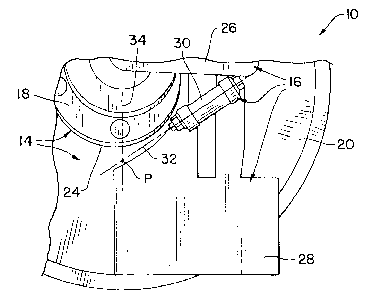
(12) Patent: (11) CA 2660666
(54) English Title: OPENER DISK BLADE SCRAPER HINGE GEOMETRY TO MAINTAIN CONTACT WITH DEFLECTED DISK BLADE
(54) French Title: GEOMETRIE ARTICULEE DE RACLOIR DE DISQUE DE CHARRUE A OUVRE-SILLON PERMETTANT DE MAINTENIR LE CONTACT AVEC LE RACLOIR DE DISQUE DEVIE
Status: Granted and Issued
Bibliographic Data
(51) International Patent Classification (IPC):
  • A01B 23/06 (2006.01)
(72) Inventors :
  • FRIESTAD, MICHAEL E. (United States of America)
(73) Owners :
  • DEERE & COMPANY
(71) Applicants :
  • DEERE & COMPANY (United States of America)
(74) Agent: BORDEN LADNER GERVAIS LLP
(74) Associate agent:
(45) Issued: 2016-11-08
(22) Filed Date: 2009-03-27
(41) Open to Public Inspection: 2009-10-10
Examination requested: 2014-03-26
Availability of licence: N/A
Dedicated to the Public: N/A
(25) Language of filing: English

Patent Cooperation Treaty (PCT): No

(30) Application Priority Data:
Application No. Country/Territory Date
12/405,487 (United States of America) 2009-03-17
61/043,904 (United States of America) 2008-04-10

Abstracts

English Abstract

An agricultural machine includes a disk blade assembly having a hub and a disk blade mounted to the hub. The hub has a perimeter. The disk blade is deflectable by ground forces in an area outside of the hub. A scraper assembly includes a mount, a scraper blade, and a hinge pivotally interconnecting the scraper blade with the mount. The hinge has an axis of rotation which passes through a point generally at or near a bottom of the hub perimeter, and generally coincident with the disk blade.


French Abstract

Une machine agricole comprend un ensemble de lames de disque avec un moyeu et une lame de disque montée sur le moyeu. Le moyeu possède un périmètre. La lame de disque peut être déviée par les forces du sol dans une zone à lextérieur du moyeu. Un ensemble racloir comprend un bâti, une lame de racloir et une charnière reliée de manière pivotante à la lame de racloir avec le bâti. La charnière présente un axe de rotation qui passe au travers dun point généralement au bas ou proche du bas du périmètre du moyeu, et généralement coïncidant avec la lame de disque.

Claims

Note: Claims are shown in the official language in which they were submitted.

CLAIMS:
1. An agricultural machine, comprising:
a disk blade assembly including a hub and a disk blade mounted to said hub,
said hub having a perimeter and an axis of rotation; and
a scraper assembly including:
a mount;
a scraper blade including a scraper portion adjacent said disk blade;
and
a hinge pivotally interconnecting said scraper blade with said mount,
said hinge having an axis of rotation which intersects with said disk blade at
a
point which is at or immediately below a bottom of said perimeter of said disk
blade hub, in an area beginning flexure of said disk blade as a result of
ground
forces applied to said disk blade, said hinge axis of rotation intersecting
with a
substantially vertical line passing through said hub axis of rotation and
contacting at least a part of said disk blade substantially at said point,
said
point being located radially inwardly of said scraper portion of said scraper
blade relative to said disk blade.
2. The agricultural machine of claim 1, wherein said substantially vertical
line is
generally coincident with said disk blade at said point.
3. The agricultural machine of claim 1, wherein said disk blade is
substantially
not deflectable by ground forces in an area of said hub, and said disk blade
is
deflectable by ground forces in an area below said hub.
4. The agricultural machine of claim 1, wherein said agricultural machine
is one
of a seeding machine and a chemical applicator.
6

5. An agricultural machine, comprising:
a disk blade assembly including a hub and a disk blade mounted to said hub,
said hub having an axis of rotation and a perimeter; and
a scraper assembly including:
a mount;
a scraper blade including a scraper portion adjacent said disk blade;
and
a hinge pivotally interconnecting said scraper blade with said mount,
said hinge having an axis of rotation intersecting with a substantially
vertical
line passing through said hub axis of rotation, said hinge axis of rotation
further intersecting with said disk blade at an intersection point which is at
or
below a bottom of said hub perimeter, said substantially vertical line
contacting
at least a part of said disk blade substantially at said intersection point,
said
intersection point being located radially inwardly of said scraper portion of
said
scraper blade relative to said disk blade.
6. The agricultural machine of claim 5, wherein said disk blade is
substantially
not deflectable by ground forces in an area of said hub, and said disk blade
is
deflectable by ground forces in an area below said hub.
7. The agricultural machine of claim 5, wherein said agricultural machine
is one
of a seeding machine and a chemical applicator.
8. An agricultural machine, comprising:
a disk blade assembly including a hub and a disk blade mounted to said hub,
said hub having a perimeter and an axis of rotation, said disk blade being
deflectable
by ground forces in an area outside of and below said hub; and
a scraper assembly including:
a mount;
7

a scraper blade including a scraper portion adjacent said disk blade;
and
a hinge pivotally interconnecting said scraper blade with said mount,
said hinge having an axis of rotation which intersects with said disk blade at
a
point which is at or below a bottom of said hub perimeter and which intersects
with a substantially vertical line passing through said hub axis of rotation
and
contacting at least a part of said disk blade substantially at said point,
said
point being located radially inwardly of said scraper portion of said scraper
blade relative to said disk blade.
9. The agricultural machine of claim 8, wherein said substantially vertical
line is
generally coincident with said disk blade at said point.
10. The agricultural machine of claim 8, wherein said disk blade is
substantially
not deflectable by ground forces in an area of said hub, and said disk blade
is
deflectable by ground forces in an area below said hub.
11. The agricultural machine of claim 8, wherein said agricultural machine
is one
of a seeding machine and a chemical applicator.
8

Description

Note: Descriptions are shown in the official language in which they were submitted.


CA 02660666 2009-03-27
OPENER DISK BLADE SCRAPER HINGE GEOMETRY TO
MAINTAIN CONTACT WITH DEFLECTED DISK BLADE
Field of the Invention
[0001] The present invention relates to disk blade assemblies used with
agricultural
equipment, and, more particularly, to opener disk blade assemblies used with
agricultural seeding machines.
Background of the Invention
[0002] Soil adhering to disk blades leads to large accumulations of soil and
crop
residue between the disk blade and boot or scraper. This is known as
"plugging"
and requires the machine operator to stop and manually remove the debris
before
continuing. Previous attempts to address this problem included changed scraper
shape, increased spring force between scraper and blade, and "jack bolts" to
force
contact between scraper and blade. Scraper shape alone has not been successful
in
eliminating the plugging. Greater spring force and jack bolts have been
marginally
successful but at the cost of increased wear, component breakage, and disk
blade
stoppage in loose, dry soil. In addition, the machine may be used to apply
anhydrous ammonia (NH3) which aggravates the problem because wet soil will
freeze and adhere to the disk blade. All known disk blade scraper designs have
the
limitation that they only match the disk blade shape in one condition,
typically flat disk
blade without soil pressure loading. The disk blade is typically placed at an
angle
relative to the forward travel direction of the seeding machine, and soil
pressure
during operation deflects the disk blade, resulting in a gap between the disk
blade
and scraper allowing soil to adhere to the blade (see Fig. 1 for exemplary
deformation of an opener disk blade).
[0003] What is needed in the art is a scraper assembly which is less prone to
plugging and befter follows the contour of a disk blade when deflected during
operation.
1

CA 02660666 2009-03-27
Summary of the Invention
[0004] The invention in one form is directed to an agricultural machine,
including a
disk blade assembly having a hub and a disk blade mounted to the hub. The hub
has a perimeter. A scraper assembly includes a mount, a scraper blade, and a
hinge
pivotally interconnecting the scraper blade with the mount. The hinge has an
axis of
rotation which lies generally tangent to the perimeter of the disk blade hub.
[0005] The invention in another form is directed to an agricultural machine,
including a disk blade assembly having a hub and a disk blade mounted to the
hub.
The hub has an axis of rotation and a perimeter. A scraper assembly includes a
mount, a scraper blade, and a hinge pivotally interconnecting the scraper
blade with
the mount. The hinge axis of rotation generally intersects with a
substantially vertical
line passing through the hub axis of rotation and coincident with the disk
blade at an
intersection point.
[0006] The invention in yet another form is directed to an agricultural
machine,
including a disk blade assembly having a hub and a disk blade mounted to the
hub.
The hub has a perimeter. The disk blade is deflectable by ground forces in an
area
outside of the hub. A scraper assembly includes a mount, a scraper blade, and
a
hinge pivotally interconnecting the scraper blade with the mount. The hinge
has an
axis of rotation which passes through a point generally at or near a bottom of
the hub
perimeter, and generally coincident with the disk blade.
Brief Description of the Drawings
[0007] Fig. 1 illustrates exemplary deformation of a disk blade assembly for a
disk
opener on a seeding machine during use in soil;
[0008] Fig. 2 is a side view of an embodiment of a scraper assembly of the
present
invention, positioned in association with a disk blade assembly;
[0009] Fig. 3 is a top view of the scraper assembly and disk blade assembly
shown
in Fig. 2.
[0010] Fig. 4 is a perspective view of the scraper assembly shown in Figs. 2
and 3;
[0011] Fig. 5 is a perspective view of another embodiment of a scraper
assembly of
2

CA 02660666 2009-03-27
the present invention which has been tested during operation; and
[0012] Figs. 6 and 7 are disassembled views of yet another embodiment of a
scraper assembly of the present invention which has been tested during
operation.
Detailed Description of the Invention
[0013] Referring now to the drawings, and more particularly to Fig. 1, it can
be seen
that the total deformation of a disk blade, which is assumed to be attached to
the hub
in the illustration, increases in an area below the hub as the radius of a
selected point
of interest increases. In the area of the hub, the disk blade of course
rotates with the
hub about an axis of rotation of the hub, but is otherwise not deflectable by
ground
forces. In fact, it is observable from Fig. 1 that the deflection of the disk
blade curves
around and begins to deflect in an area immediately outside of and below the
hub.
Since the ground forces are only exerted against the disk blade in an area
below the
hub, conversely there are no substantial deflections in an area above the hub.
[0014] Referring now to Figs. 2-4, there is shown a portion of an agricultural
machine 10, including a disk blade assembly 14 and a scraper assembly 16. In
the
embodiment shown, agricultural machine 10 is assumed to be a seeding machine
in
the form of a row crop planter and each disk blade assembly 14 is associated
with a
respective row unit (not shown). It is also possible that disk blade assembly
14 and
scraper assembly 16 can be associated with a different type of agricultural
machine,
such as a chemical applicator in the form of a liquid or dry fertilizer,
herbicide, and/or
insecticide applicator.
[0015] Disk blade assembly 14 includes a hub 18 and a disk blade 20 which is
mounted to hub 18. Hub 18 has an axis of rotation 22 and a perimeter 24. In
the
area radially within perimeter 24 of hub 18, disk blade 20 is substantially
non
deflectable by ground forces applied during application, and in an area
radially
outside of perimeter 24 disk blade 20 is deflectable by ground forces which
are
applied during operation.
[0016] Scraper assembly 16 includes a mount 26, scraper blade 28, and hinge
30.
Mount 26 is attached to and carried by any suitable carrying structure
associated with
3

CA 02660666 2009-03-27
disk blade assembly 14, such as a suitable frame member or the like. Hinge 30,
to
be described in more detail below, interconnects scraper blade 28 with mount
26.
[0017] More particularly, scraper assembly 16 of the present invention is
configured
to follow the deflected disk blade shape, maintaining contact at all times to
eliminate
adhering soil and subsequent plugging. This effect is accomplished by choosing
the
scraper hinge angle to point generally toward the perimeter 24 of disk blade
hub 18.
Referring to Fig. 2, scraper assembly 16 has a hinge 30 with an axis of
rotation 32
which generally lies along (i.e., is generally tangent to) the perimeter 24 of
hub 18.
As shown in Figs. 2 and 3, axis of rotation 32 is also preferably positioned
to
generally align with a vertical line 34 passing through axis of rotation 22 of
hub 18 at
an intersection point P which is also immediately below hub 18 and generally
coincident with disk blade 20.
[0018] Put another way, the axis of rotation 32 of hinge 30 is oriented to
pass
through a point coincident with disk blade 20 immediately below hub 18 where
the
deflections of disk blade 20 begin to occur during operation. This allows
scraper
blade 28 to more closely follow the contour of disk blade 20 when deflected
during
operation. The intersection point P is generally at the perimeter of hub 18,
meaning
that it need not be exactly at the perimeter of hub 18, but rather at or near
hub 18 in
an area below hub 18 where deflections begin to occur outside the perimeter
24.
[0019] Scraper blade 28 cannot exactly follow the disk blade 20 due to blade
curvature when loaded but it's far closer than current production. In fact,
scraper
blade 28 will likely wear in to match nominal disk blade curvature and has
been
shown to keep disk blade 20 clean in representative field conditions. Field
tests to
date have shown effective disk blade cleaning with lower spring force. This is
expected to reduce component wear for longer life. Of further benefit, scraper
blade
28 can swing up a full 90 degrees and be self-clearing of plugs.
[0020] Referring to Fig. 5, there is shown an assembled, perspective view of
an
embodiment of a scraper assembly 40 of the present invention which has been
tested to be effective during operation. Figs. 6 and 7 illustrate disassembled
views of
another embodiment of a scraper assembly 50 of the present invention which has
4

CA 02660666 2009-03-27
been tested to be effective during operation.
[0021] Having described the preferred embodiment, it will become apparent that
various modifications can be made without departing from the scope of the
invention.

Representative Drawing
A single figure which represents the drawing illustrating the invention.
Administrative Status

2024-08-01:As part of the Next Generation Patents (NGP) transition, the Canadian Patents Database (CPD) now contains a more detailed Event History, which replicates the Event Log of our new back-office solution.

Please note that "Inactive:" events refers to events no longer in use in our new back-office solution.

For a clearer understanding of the status of the application/patent presented on this page, the site Disclaimer , as well as the definitions for Patent , Event History , Maintenance Fee  and Payment History  should be consulted.

Event History

Description Date
Common Representative Appointed 2019-10-30
Grant by Issuance 2016-11-08
Inactive: Cover page published 2016-11-07
Inactive: Final fee received 2016-09-30
Pre-grant 2016-09-30
Change of Address or Method of Correspondence Request Received 2016-09-30
Notice of Allowance is Issued 2016-04-07
Letter Sent 2016-04-07
Notice of Allowance is Issued 2016-04-07
Inactive: Approved for allowance (AFA) 2016-03-31
Inactive: Q2 passed 2016-03-31
Amendment Received - Voluntary Amendment 2015-11-19
Inactive: S.30(2) Rules - Examiner requisition 2015-05-28
Inactive: Report - No QC 2015-05-27
Letter Sent 2014-04-02
Request for Examination Requirements Determined Compliant 2014-03-26
All Requirements for Examination Determined Compliant 2014-03-26
Request for Examination Received 2014-03-26
Application Published (Open to Public Inspection) 2009-10-10
Inactive: Cover page published 2009-10-09
Inactive: IPC assigned 2009-09-11
Inactive: First IPC assigned 2009-09-11
Inactive: Declaration of entitlement - Formalities 2009-05-14
Filing Requirements Determined Compliant 2009-04-29
Inactive: Filing certificate - No RFE (English) 2009-04-29
Application Received - Regular National 2009-04-28
Inactive: Inventor deleted 2009-04-28
Reinstatement Requirements Deemed Compliant for All Abandonment Reasons 2009-03-27

Abandonment History

There is no abandonment history.

Maintenance Fee

The last payment was received on 2016-03-02

Note : If the full payment has not been received on or before the date indicated, a further fee may be required which may be one of the following

  • the reinstatement fee;
  • the late payment fee; or
  • additional fee to reverse deemed expiry.

Patent fees are adjusted on the 1st of January every year. The amounts above are the current amounts if received by December 31 of the current year.
Please refer to the CIPO Patent Fees web page to see all current fee amounts.

Owners on Record

Note: Records showing the ownership history in alphabetical order.

Current Owners on Record
DEERE & COMPANY
Past Owners on Record
MICHAEL E. FRIESTAD
Past Owners that do not appear in the "Owners on Record" listing will appear in other documentation within the application.
Documents

To view selected files, please enter reCAPTCHA code :


To view images, click a link in the Document Description column. To download the documents, select one or more checkboxes in the first column and then click the "Download Selected in PDF format (Zip Archive)" or the "Download Selected as Single PDF" button.

List of published and non-published patent-specific documents on the CPD .

If you have any difficulty accessing content, you can call the Client Service Centre at 1-866-997-1936 or send them an e-mail at CIPO Client Service Centre.


Document
Description 
Date
(yyyy-mm-dd) 
Number of pages   Size of Image (KB) 
Description 2009-03-26 5 214
Abstract 2009-03-26 1 16
Claims 2009-03-26 3 87
Drawings 2009-03-26 4 76
Representative drawing 2009-09-16 1 11
Claims 2015-11-18 3 97
Maintenance fee payment 2024-03-21 45 1,853
Filing Certificate (English) 2009-04-28 1 157
Reminder of maintenance fee due 2010-11-29 1 112
Reminder - Request for Examination 2013-11-27 1 117
Acknowledgement of Request for Examination 2014-04-01 1 176
Commissioner's Notice - Application Found Allowable 2016-04-06 1 161
Correspondence 2009-04-28 1 18
Correspondence 2009-05-13 2 56
Amendment / response to report 2015-11-18 6 310
Change to the Method of Correspondence 2016-09-29 1 41