Note: Descriptions are shown in the official language in which they were submitted.
CA 02660697 2009-02-13
WO 2008/019430 PCT/AU2007/001138
SINGLE USE SELF-DISABLING SYRINGE
Technical Field
This invention relates to a syringe. In particular, it relates to a single
use, self-disabling
syringe.
Background
Syringes are a necessary implernent in the medical field. Throughout the
world, the
multiple use of hypodermic syringe products that are intended for single use
only is
instrumental in drug abuse axad-more particularly in the transfer of
contagious
diseases. Intravcnous drug users who routinely share and reuse syringes are a
high
ia risk group with respect to the AIDS virus. Also, the efI'ects of multiple
use are a
major concern in third world countries where repeated use of$yringe products
may
be responsible for the spread of many diseases. 'Reuse of single usc syrittge
:
assemblies is also instrumentai in the spread of drug abuse even in the
absence of
infection disease.
Many attempts have been made to remedy this probiem. Some of these attempts
have
required a specific act to destroy the syringe after use either by using a
destructive
device or providing a syringe assembly with frangible zones so that the
syringe could
be rendered inoperable by the application of forcc. Furthermore with the high
cost of
production it is not easy to produce in a high quantity.
2o Obiect of the Invention.
It is therefore an object of the present invention to providc a unique and new
invention and design for a single use self disabling syringe which solves at
least one
major problem, namely to provide a single use and self-disabling syringe,
where the
construction isreasonably simple, the development of the moulds and assembling
is
easy and the syringe is completely destroyed after use.
At the very least, the invention provides an alternate single use syringes.
1
SUBSTITUTE SHEET (RULE 26) RO/AU
CA 02660697 2009-02-13
WO 2008/019430 PCT/AU2007/001138
Disclosure of the Inyention
According to the present invention, there is provided a single use self-
disabling
syringe, which includes a barrel, a plunger, and a rubber seal located on the
plunger
and providing a seal between the plunger and the barrel, wherein at the end of
the
s barrel there is a needle set, and at the front end of the plunger there is a
clip, such that
the clip can completely block the needle set, the syringe characterised in
that the said
needle set and barrel is a one-piece moulded, integrated unit; the said barrel
has a
supporting body at the front end, wherein the supporting body and the inside
wall of
the barrel fit tightly together; the said supporting body having a flexible
hook on its
lo top; and the said clip has a cone step to engage with the flexible hook to
make sure
they match and seal.
Preferably, the hook has two or more flexible metal arms to assist in engaging
with
the clip. According to the above embodiment, it will be understood that this
one-
piece construction of the needle set and barrel lowers the production cost;
the flexible
1s metal arms and the clip hooked up tight and strong, such that when the
plunger is
pulled back there is no opportunity of the clip of the plunger disengaging
from the
hook; and the structure for this supporting body is simple and much easier to
assemble.
In order to solve the technical issues, this practical new invention has taken
on other
zo embodiments. The said barrel has a supporting body at the front end, the
supporting
body and the inside wall of barrel working perfectly close for a tight fit;
this designed
structure makes the supporting body and the barrel easier to assemble and
stable.
The said top of the barrel is provided with a concave groove and a matching
convex
ridge is provided on the outside bottom end of the supporting body which fit
tightly
25 against each other at the top end of the barrel. This structure makes the
function of
the supporting body more reliable.
The said clip and the plunger are moulded in one piece, which simplifies the
production technology of the syringe and decreases the cost.
2
CA 02660697 2009-02-13
WO 2008/019430 PCT/AU2007/001138
The said plunger is provided with several easy-to-break points. These points
make
sure that when the plunger is pulled back, the plunger will break and be self-
disabled
at the line along the easy-to-break points, thereby achieving the goal of
completely
self-disabling the syringe.
Preferably there is also provided a stopper on the bottom, ie free end, of the
plunger.
Accordingly there is a specially designed passing hole at the bottompart of
the
plunger to acconimodate the stopper. There are two easy-to-break points along
a line
and the stopper combines as one piece with a point on bottom of the plunger,
the
stopper moving along with the point. Two inside walls of the said passing hole
have
io a vein on each side, and the veins are elevated. The stopper thus avoids
any accident
that might destroy the syringe itself during transport and prior to use, ie
before
drawing the fluid.
According to another embodiment of the invention, there is provided a single
use
self-disabling syringe including a hollow barrel, a plunger and a rubber seal
which
1s sits on the top end of the plunger, the top end of the barrel being a one-
piece moulded
needle set, the top end of the plunger having a clip associated therewith, so
the clip
can block the inside of the said needle set, the syringe being characterised
by having
the said needle sct and barrel as a one-piece moulded unit; the top end of the
barrel
and the needle set having a circle of convex steps; the said clip having a
flexible
zo metal component, and at the top of the metal component there are flexible
metal
arms; the said clip and the flexible metal arms having complementary cone
shapes so
as to match.
By this means, this one-piece needle set and barrel lowers the cost; the
flexible metal
arms and the clip tightly hold, so that when the plunger is pulled back it
doesn't
25 disengage; and the simple structure.makes assembly even easier.
In order to solve the technical problems, there are further embodiments.
Accordingly, there is a single use self-disabling syringe for which the metal
component is a hollow circular cone, and the flexible metal arms extend in two
3
CA 02660697 2009-02-13
WO 2008/019430 PCT/AU2007/001138
directions. This structure makes the flexible metal arms easier to pass
through the
cone step provided at the junction between the top end of the barrel with the
needle
set.
Preferably, this is a single use self-disabling syringe which has the feature
whereby
the said clip and the plunger can be separated, when the injection is
finished, by
pulling the plunger back with extra force, so as to make the plunger and the
clip
separate. The rubber seal also comes off, causing the clip to fall inside the
barrel so
that it won't come out, thereby achieving complete self disabling of the
syringe.
Although the following deseription generally refers to a syringc of
conventional size,
,o no such limitation is intended thereby, and reference to a syringe is meant
to
encompass any other needle/syringe combination or needle alone including
slimline
syringes, where, by suitable adaptation, the invention may also bc usefully
applied.
Brief Description of the Drawin s
The invention may be better understood from the following non-limiting
description
of preferred embodiments, in which:
Fig 1 is a cross-sectional side view of a syringe according to a first
embodiment of
the invention showing the syringc prior to usc;
Fig 2 is a cross-sectional side vicw of the syringe of Fig 1, when the syringe
has
finished drawing the fluid;
2o Fig 3 is a cross-sectional side view of the syringe of Fig 1, after the
syringe has
finished injection and in the first step of self-disabling;
Fig 4 is a cross-sectional side view of the syringe of Fig 1, when the self-
disabling
state is completed;
Fig 5 is a cross-sectional side view of the barrel of the syringe of Fig 1;
Fig 6 is a cross-sectional side view of the supporting body of the syringe of
Fig 1.
Fig 7 is a cross-sectional plan view of the supporting body of Fig 6;
4
CA 02660697 2009-02-13
WO 2008/019430 PCT/AU2007/001138
Fig 8 is a cross-sectional side view of the plunger of the syringe of Fig 1;
Fig 9 is a cross sectional plan view of the plunger of Fig 8 when viewed from
the
direction shown as A to A in Fig 8;
Fig 10 is a further cross sectional side view of the plunger of Fig 8 whcn
viewed
s from the direction shown as K in Fig 8;
Fig 1 I is a partial magnified portion of the Fig 1;
Fig 12 is a cross-sectional side view of a syringe according to a second
embodiment
prior to use;
Fig 13 is a cross-sectional side view of the syringe of Fig 12 when the
syringe has
lo fmished drawing the fluid;
Fig 14 is a cross-sectional side view of the syringe of Fig 12 after the
syringe has
finished injection and in the first step of self-disabling;
Fig 15 is a cross-sectional side view the syringe of Fig 12 when the self-
disabling
state is completed;
15 Fig 16 is a cross-sectional side view of the barrel of the syringe of Fig
12;
Fig 17 is a cross-sectional side view of the plunger and the clip of the
syringe of Fig
12;
Fig 18 is a perspective view of the flexible metal arms of the syringe of Fig
12;
Fig 19 is a partial magnified portion of Fig 12.
2o Detailed Description of the Drawings
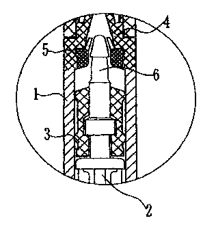
Referring generally to Figs 1 to 11, there is shown a first embodiment of the
invention, being a single use self-destructing syringe including a barrel (1),
a plunger
(2), a rubbcr seal (3). At the end of the barrel (1) there is a needle set
(4). At the
front end the plunger (2) there is a clip (6), which can completely block the
needle set
25 (4), as shown in Fig4. The said barrel (1) has onc supporting body (5) at
the front
end, the supporting body (5) and the inside wall of barrel (1) fitting
tightly. The said
CA 02660697 2009-02-13
WO 2008/019430 PCT/AU2007/001138
supporting body (5) has a flexible hook comprising at least two fmgers (512)
on its
top, as shown in Figs 6 and 7. The supporting body (5), which is preferably
metal, is
placed at the top end of the barrel (1).
Referring to Figs 8 to 10, there is shown the clip (6) which is set at the top
end of the
s plunger (2), and this is a one-piece moulded unit. There is a pointy step
(611) that
can easily go through the flexible metal arms (512), so that when the plunger
(2)
pushes the fluid during an injection, the clip (6) goes into the flexible arms
(512), and
thcn finally the flexible arms (512) stop or engage against at the base of the
pointy
step (611), so that the clip (6) can't pull back. In this way, the clip (6)
can block the
,o inside hole of needle set (4), so as to finish the first step if self-
disabling.
There are several easy-to-break points on the plunger (2), and in this
embodiment for
example there are shown three points A, B, C in Fig 8. When the injection is
finished
and the plunger (2) pulled back, pulling will cause the plunger to break at
the points
along the easy-to-break points, thereby disabling the plunger (2) against re-
use again,
15 therefore completely achieving the goal of self- disabling.
As stated before, this is a single use self-disabling syringe, and further
special points
are included. These include a stopper (7), and a specially designed passing
hole (8)
at the bottom part of the plunger (2) which accommodates the stopper (7).
There are
two easy to break points (9) in a line. These are combined as one piece with a
point
20 (10) on top of the plungcr (2), the stopper (7) moving along with the point
(10). Two
inside walls of the said passing hole (8) each have a vein (11) on each side,
and the
veins are elevated. When the fluid is injected, it is only necessary to push
gently
toward. the stopper (7) so as to make the stopper (7) move along the point
(10), so as
to cause the easy-to-break points (9) to break. This also stops the accidental
self-
26 disabling prior to use during transport and/or through any unneeessary
mistakes.
Referring to Figs 1 to 4, the operation of this new practical invention is
shown. In
Fig 1, there is shown the syringc prior to use, the clip (6) hasn't pass
through the
flexible hook (512), and in the meantime is prevented from mis-operation. In
the
6
CA 02660697 2009-02-13
WO 2008/019430 PCT/AU2007/001138
following drawing Fig2, the syringe is shown when drawing of the fluid is
finished,
after the needle protection cap (411) and the protection lid (211) for the
plunger have
been removed. Also the outside surface of stopper (7) fits in the passing hole
(8).
As per Fig 3, when the injection is finished, the pointy step (611) of the
said clip (6)
s will pass through the flexible metal hook (512) and this time, the hook
(512) and the
pointy step (611) click together and stop the clip (6) from moving, thereby
blocking
the inside surface of the needle set (4) by the clip (6), so that you couldn't
reuse the
syringe, thus finishing the first step of self-disabling. As shown in Fig 4,
there is
shown the moment that self-disabling is completed. Pulling harder makes sure
the
lo plunger (2) is broken and the top end of the plunger breaks iriside the
barrel (1) but
can't come out. This prevents the plunger (2) and rubber seal (3) from being
changed
so to prevent reuse again, and therefore the syringe is completely self-
disabled.
Referring generally to Figs 12 to 19, there is shown a second embodiment of
the
invention being a single use self-destructing syringe which includes a barrel
(1),
15. plunger (2), rubber seal (3), needle set (4), flexible metal hook (5'),
clip (6), wherein
the flexible metal hook (5') sits on top of the clip (6).
Viewing Fig 16, the said needle set (4) and barrel (1) is a one-piece moulded,
integrated unit. The said barrel (1) has a supporting body (5) at the front
end, the
supporting body (5) and the inside wall of barrel (1) fitting tightly. The
said
2o supporting body (5) has a flexible hook (512) on its top. The said clip (6)
and the
hook (512) have a pointy step (611) to make sure they match and seal properly.
Fig
17 shows the top end of the plunger (2) has one clip (6) and we previously
indicated,
they click together, but doesn't mean the needle is totally blocked. However,
you
only need to pull harder, and it will be apart from each other. A pointy step
(611) is
25 formed at the top end of the clip (6).
At the bottom end of the plunger (2), there is a designed stopper (7), the
structure of
the stopper (7) is same as the for the first embodiment shown in Figs 1 to 11
and
functions in the same way.
7
CA 02660697 2009-02-13
WO 2008/019430 PCT/AU2007/001138
Referring to Fig 18, the metal hook (5') is made from metal and the main body
is a
hollow cone shaped part, and the top thereof is provided with flexible arms
(513)
with at least two such arms extending in two directions as shown, This
flexible hook
(513) is used so as to function in the same way as the previous embodiment
where
s metal arms (512) were utilised. Once pushing the fluid is finished, the clip
(6) passes
through the step (113) that joins at the end of the barrel (1) with needle set
(4). The
end of this metal hook (513) is pushed against by the step (311), the top end
is
positioned by pointy step (611), so the clip (6) can't pull back again, and
the clip (6)
blocks the gateway of needle set (4),
io Referring to Figs 12 to 15 there are shown the steps involved in using and
disabling
the syringe. Referring to Fig 12, the syringe is shown prior to use, clip (6)
hasn't
passed through the convex step (113) of the joint between barrel (1) and the
needle
set (4), and also to avoid any accident or mis-use, the stopper (7) sticks
against the
bottom end of the barrel (1).
15 And then the following drawing, Fig 13, shows the syringe when drawing the
fluid
has finished, at this stage, the needle cap (411) and plunger lid (211) both
having
been taken off, and the outside surface of stopper (7) fits in the passing
hole (8). As
per Fig 14, when the injection is finished, the pointy step (611) of the
mentioned clip
(6) will pass through the flexible metal hook (512) and this time, the hook
(512) and
zo the pointy step (611) click together and stop the clip (6) from moving,
thereby
blocking the insidc surface of the needle set (4) by the clip (6), so that the
syringe
cannot be reused, completing the first step of self-disabling.
As shown in Fig 15, the syringe has i'inished the self-disabling, pulling
harder having
made sure the plunger (2) is broken. The top end of the plunger breaks inside
the
25 barrel (1) but can't come out, in order to avoid the plunger (2) and rubber
seal (3)
from being changed and thereby preventing the syringe from being reused again.
Consequently, the syringe is completely self-disabled.
8
CA 02660697 2009-02-13
WO 2008/019430 PCT/AU2007/001138
It will be appreciated by those skilled in the art that many modifications and
variations
may be made to the embodiments described herein without departing from the
spirit or
scope of the invention.
Throughout the specification the word "comprise" and its derivatives are
intended to
s have an inclusive rather than exclusive meaning unless the context requires
otherwise.
9