Note: Descriptions are shown in the official language in which they were submitted.
CA 02661065 2009-02-18
WO 2008/025945
PCT/GB2007/003091
1
= Fluidic Indicator Device
Field of the Invention
The invention relates to a fluidic device for the passage of a liquid. It also
relates to an
assay device suitable for measurement of the amount and/or presence of an
analyte in, or
property of, a fluid sample.
Background of the invention
Simple disposable fluidic devices for the detection of an analyte are known.
EP291194
discloses an assay device comprising a lateral flow porous carrier wherein
accumulation of
a particulate labelled binding reagent in a detection zone provides a visible
signal to the
user of the presence or absence of analyte in a liquid sample. The signal
however requires
interpretation by the user. Digital devices have been developed as a
consequence wherein
on-board optics are able to measure the presence or intensity of the labelled
reagent and
provide an absolute answer which does not require interpretation. Digital
devices however
are expensive to produce as they require in addition to the optical
components, a power
source further processing electronics and a digital display.
US4963498 discloses a microfluidic device for the measurement of an analyte
in, or
property of a fluid sample wherein reagents present in the device affect the
flow rate of the
sample. The device may comprise both a test capillary and a reference or
control
capillary.
EP456699 discloses an apparatus for testing the presence of a substance in a
liquid
comprising a sample application port connected to a number of fluid conduits
upstream
from respective indicator chambers. According to an example, agglutination
reagents
present in the fluid conduits interact with the sample in order to change its
flow rate, for
example, preventing the liquid from reaching an indicator chamber within the
time frame
of the assay.
CA 02661065 2009-02-18
WO 2008/025945
PCT/GB2007/003091
2
A capillary device for testing for the presence of a substance is also
disclosed by
W02004/083859. The device works by causing agglutination of a liquid sample in
a test
capillary in the presence of an analyte of interest (typically, human
chorionic
gonadotrophin, hCG), which agglutination ,prevents the flow of liquid sample
in the test
capillary but not in a control capillary (which contains no agglutination
reagents). The
presence or absence of liquid sample at downstream portions of the test and
control
capillaries is detected by electrodes.
A problem associated with non-digital assay devices, especially pregnancy-
testing devices
and/or home-use assay devices, is that they provide an assay result as a
signal of variable
strength, which can require a degree of interpretation. This leaves the assay
result open to
misinterpretation, especially where the user or reader of the assay device has
a preferred
assay result in mind. In the case of some testing devices however, such as a
pregnancy-
testing device, it is preferred to configure the device such that no
interpretation is required
and the assay result is provided as one of two alternatives (i.e. pregnant or
not pregnant).
This may be described as a "binary outcome" device. This provides an
unequivocal result
which removes the need for interpretation by the user, which is undesirable.
This problem
has been addressed in the prior art by the provision of assay devices or assay
device
readers incorporating complicated optical and electronic components to read a
variable
strength signal and then provide a binary outcome via an electronic (e.g. LCD
or LED)
display. The present invention provides, in preferred embodiments a simpler
method of
providing a binary outcome assay device which is far simpler to produce than
existing
optical/electronic assay devices.
Summary of the Invention
In a first aspect the invention provides a fluidic assay device for assaying
at least one
property of a liquid sample, the device comprising:
(i) = a liquid sample application region;
=
CA 02661065 2009-02-18
WO 2008/025945
PCT/GB2007/003091
3
(ii) at least one test flow path in liquid flow communication with the
sample application
region;
(iii) a reference path in liquid flow communication with the sample
application region;
and
(iv) a junction region, at which the test flow path and the reference flow
path contact
one another, the junction region typically comprising an outlet, conduit,
chamber or
other portion which permits the onward flow of liquid;
wherein a liquid flowing along the reference flow path, upon reaching the
junction
region, has the effect of preventing the flow of liquid along the test flow
path.
Conversely, in the event that liquid flowing along the test flow path reaches
the
junction region before liquid from the reference flow path it is possible, at
least in
some embodiments, that the flow of liquid along the reference flow path may be
prevented. Prevention of the flow of liquid along the reference or test flow
path is
not necessarily permanent: it is sufficient for the flow of liquid to be
prevented
within the timescale in which the assay is performed and read.
The test flow path and/or the reference flow path may comprise or consist of a
microfluidic channel, a porous carrier, or a combination of the two. Preferred
porous
carriers include nitrocellulose and filter paper. The microfluidic channel is
preferably of
capillary dimensions such that a typical sample liquid is able to flow along
the channel by
capillary flow. Preferably the test and/or reference flow paths comprise or
consist of
channels having at least a portion with a capillary dimension.
=
Typical microfluidic channels have an internal cross-sectional dimension of
between 0.1
and 500pm, more typically between 1 and 100pm. The microfluidic channels may
be
formed from synthetic plastics materials such as polycarbonate, epoxy resin
CA 02661065 2009-02-18
WO 2008/025945
PCT/GB2007/003091
4
etc., glass or metal. The channels may be formed by etching, casting, moulding
etc. using
conventional techniques.
Typically, but not necessarily, the property of the liquid sample which is
assayed
comprises the presence and/or amount of an analyte of interest. The analyte of
interest
may comprise, for example, a steroid, a hormone, a peptide or ,polypeptide, a
carbohydrate, a lipid, a lipoprotein, a polynucleotide, an enzyme, a blood
group marker, a
disease marker, a diagnostic or prognostic indicator, a cation, an anion, or a
molecular
complex such as a virus, bacterium, yeast, fungus, spore or eukaryotic cell.
In one
preferred embodiment the analyte of interest comprises hCG. In another
embodiment, the
analyte is glucose. A property of a liquid sample that may be determined may
be for
example a coagulation property of blood or plasma such as prothombin time,
partial
activated thromboplastin time, thrombin time, and activated clotting time.
The assay device may comprise a control, wherein the control is capable of
generating a
signal which indicates that sample has been correctly applied to the sample
application
region and that the assay device is working normally. The control may comprise
a control
flow path having one or more reagents therein. The reference flow path may
also act as a
control.
Conveniently the control flow path is such that sample liquid applied to the
sample
application region will flow along the flow path and typically to an indicator
region, either
upstream or downstream of the junction region and there generate a signal,
typically a
visible signal.
The test flow path will generally be substantially similar in character to the
reference flow
path, but will typically comprise one or more reagents or binding partners
which will react
with or bind to the analyte of interest. Preferably such reaction or binding
event has the
effect of altering (typically decreasing) the rate of flow of sample liquid
along the test flow
path.
CA 02661065 2009-02-18
WO 2008/025945
PCT/GB2007/003091
The device of the invention can readily be configured to assay for the
presence and/or
amount of two or more analytes of interest by providing a two or more test
flow paths and,
optionally, a corresponding number of reference flow paths.
5 In one embodiment, a separate sample application port or input is
provided in the sample
application region for each test flow path. In another embodiment the sample
application
region comprises a common sample application port or input, such that sample
liquid
applied thereto may flow into two or more flow paths (e.g. two or more test
flow paths; or,
at least a test flow path and a reference flow path). Preferably the device
comprises a
common sample application port or input which supplies sample liquid to all
flow paths
present in the device, such that a single sample application step is
sufficient to initiate the
assay.
The liquid sample may be any suitable liquid, such as water, sewage sample, or
an
aqueous extract (e.g. an aqueous food or drink sample) or a biological sample
e.g. blood,
plasma, serum; urine, pus, sweat, saliva, vaginal fluid, or tears. A preferred
sample is
urine. The liquid sample may be applied to the device 'neat' or may be
subjected to a
pretreatment step (e.g. including one or more of the following: mixing;
agitation;
sonication; dilution; incubation; denaturation; or reaction with one or more
reagents).
Performance of the assay conveniently comprises reacting or interacting the
sample with
one or more substances which have the capacity to affect the rate of flow of
liquid sample
along the test flow path in order to provide an indication or measure of the
presence and/or
amount of an analyte in, or other property of, the fluid sample. Preferably at
least one of
the substances will be provided within the assay device, but additionally or
alternatively
one or more such substances may be mixed with the sample prior to application
of the
sample to the assay device. Generally, reaction or interaction of the
substance(s) with the
sample will tend to alter (i.e. increase or decrease) the rate of progress of
sample along the
test flow path. The substance(s) may be such as to increase the rate of flow
of sample
liquid along the test flow path if the sample comprises an analyte of interest
above a certain
minimum detectable concentration. More preferably however the effects of the
CA 02661065 2009-02-18
WO 2008/025945
PCT/GB2007/003091
6
substance(s) are such as to impede or decrease the rate of flow of sample
liquid along the
test flow path if the sample comprises the analyte(s) of interest.
In a preferred embodiment the device comprises one or more reagents which
react with, or
binding partners which bind to, the analyte(s) of interest. Convenient
.binding partners
comprise antibodies or antigen-binding fragments thereof (such as Fab, Fv,
scFv, domain
antibodies and the like), or multimers of antibodies or antigen-binding
fragments thereof.
Other suitable binding partners (depending on the nature of the analyte of
interest) may
comprise, for example, biotin, streptavidin, complementary polynucleotides
(comprising
10 or more, preferably 17 or more, bases of DNA, RNA, PNA, LNA or any
combination
thereof, optionally including modified or non-naturally occurring bases), and
polypeptide
receptors or at least portions thereof which retain binding activity for their
respective
ligand. Receptors include both prokaryotic and eukaryotic polypeptides,
numerous
examples of which (both full length and truncated) are known.
The reagents or binding partners may be immobilised on the assay device (i.e.
remain
attached during performance of the assay) or may be releasably attached (i.e.
are released
from a support during performance of the assay), or may comprise a combination
of
immobilised and releasably attached reagents or binding partners. For example,
in one
embodiment, a releasably attached binding partner is provided on a porous
carrier located
at an upstream portion of the test flow path. In another embodiment an
immobilised
binding partner is provided in the test flow path. In yet another embodiment a
releasably
attached binding partner is provided (on a porous carrier or otherwise) at a
relatively
upstream portion of the test flow path and an immobilised binding partner is
provided at a
relatively downstream portion of the test flow path. Methods of releasably
attaching or of
immobilising antibodies and the like on surfaces are well known to those
skilled in the art.
Conveniently a binding partner is provided within a capillary channel forming
part of the
test flow path.
CA 02661065 2009-02-18
WO 2008/025945
PCT/GB2007/003091
7
The binding partner or reagent may advantageously be labelled. Suitable labels
include,
but are not limited to, an enzyme, a fluorescent dye, a coloured dye and a
particle of
colloidal gold or other colloidal metal.
According to an embodiment, the presence of analyte may cause an increase in
the flow
rate of fluid in the test channel. For example binding of an analyte may cause
displacement of a species which is conjugated to a detergent, the presence of
which in the
fluid channel results in an increase in flow rate of the sample.
Conveniently the binding partner is particulate or comprises a particulate
substance. In
one embodiment the binding partner comprises a latex particle or a particle of
colloidal
gold or other metal. Advantageously the particle comprises a plurality of
binding partner
molecules, such that a single particle may simultaneously be bound to a
plurality of
members of the analyte of interest. Preferably the latex particle is loaded or
marked with a
direct visual label, such as a coloured dye.
In an embodiment the binding partner or partners are such that an
agglutination reaction
occurs in the test flow path in the presence of the analyte of interest, which
agglutination
reaction serves to retard or inhibit the flow of sample liquid along the test
flow path. The
effect of such retardation or inhibition of flow along the test flow path is
that liquid
flowing along the reference or control path will reach the junction region
first, which in
turn blocks the further advance of liquid along the test flow path (as
explained below).
In a further embodiment, the test flow path may comprise a reagent such as
thromboplastin, or one or more of the various clotting factors, for the
determination of a
coagulation property of blood or plasma.
According to a further embodiment, the reagent may be Concanavalin A which is
able to
react with glucose to cause an increase in viscosity in the fluid sample. The
test flow path
may comprise a solvent swellable polymer gel which swells in the presence of a
particular
CA 02661065 2009-02-18
WO 2008/025945
PCT/GB2007/003091
8
solvent to cause an increase in viscosity. An example of such is a dextran
polymer when
the analyte to be detected is water.
The assay device of the present invention can be thought of as using a "race"
between the
liquid flowing along the test flow path and that flowing along the reference
flow path - the
= first liquid to reach the junction region will win the "race" and block
further advance of
liquid along the other flow path.
One way of forming the block is to provide a number (one or more) of vents
downstream
of the junction region. Displacement of the gas (typically air) filling the
microfluidic
channel of the test and flow paths, via these vents, is necessary to allow
liquid to advance
along the flow paths. However, once liquid from one of the flow paths has
reached the
= junction it prevents the venting of gas from the other flow path, forming
a gas block
(typically an air block), preventing liquid advancing along the blocked flow
path. This
arrangement is extremely simple, requires no moving parts, and is easy to
manufacture.
One or both of the test and reference flow paths may additionally comprise
partial barriers
to flow, such as constrictions, filters, weirs or the like, which encourage
the formation of
more total barriers or obstructions in the presence of e.g. an agglutination
reaction.
Typically such a partial barrier or obstruction is provided in the one or more
test flow
paths but not in the reference flow path.
The device conveniently comprises at least one indicator region. In one
embodiment there
is an indicator region located downstream of the junction region. In one
embodiment there
is an indicator region located upstream of the junction region. In one
embodiment there is
an indicator region in or on the test flow path and an indicator region in or=
on the
reference flow path, both indicator regions being located between the sample
application
region and the junction region.
=
CA 02661065 2009-02-18
WO 2008/025945
PCT/GB2007/003091
9
The indicator region comprises a display which displays information about the
assay result
to a person using the assay device. Typically the assay result is displayed,
at least in part,
by a colour change.
There are a great many ways by which a colour change, visible in the indicator
region or
regions of the device, could be effected.
In one example, there is an indicator region downstream of the junction
region. In a
simple embodiment, dyes of different colours are provided in the respective
test and
control flow paths, such that the presence of a dye of a particular colour in
the indicator
region reveals by which route (the test or control flow path) liquid first
reached the
indicator region. Alternatively, two different enzymes (e.g. horseradish
peroxidase and
glucose oxidase) could be provided in the indicator region, and a respective
substrate for
one of the enzymes could be provided in the flow paths which, reacts, in the
presence of
the relevant enzyme catalyst, to produce a coloured product. The colour of the
product
reveals which substrate was introduced into the indicator region (and hence by
which flow
path liquid first arrived there). In general terms, the indicator region (if
located
downstream of the junction region) may comprise components of two different
signal-
generating means which generate detectably different signals, with one or more
further
components of each signal-generating means being mobilisably disposed
upstream, the
further component of one signal-generating means being disposed in the test
flow path, and
the further component of the other signal-generating means being disposed in
the reference
flow path, the further component being required to contact the other component
in the
indicator region in order to generate a signal. Which of the two signal-
generating means is
activated depends on which of the further components reaches the indicator
region first,
which in turn depends on the relative rates of flow of liquid along the test
and reference
flow paths.
In one embodiment, the indicator region comprises a pH-sensitive indicator,
and the test
and reference flow paths each comprise a different pH-affecting agent e.g. one
comprises a
buffer at relatively acidic pH and one comprises a buffer at relatively
alkaline pH. The
CA 02661065 2009-02-18
WO 2008/025945
PCT/GB2007/003091
flow path by which liquid first reaches the indicator region will therefore
determine the pH
in the indicator region and hence the colour of the indicator.
Embodiments of this general type, with a downstream indicator region, have the
advantage
5 that it is not necessary to impede or retard the flow of liquid along the
test flow path by a
large amount in order for the liquid flowing along the reference flow path to
reach the
indicator region first - a time differential of as little as 1 or 2 seconds
will suffice.
In other embodiments an indicator region is provided, upstream of the junction
region, in
10 each of the reference and the test flow paths. In one embodiment, flow
of liquid along the
reference flow path to a certain point acts to block flow of liquid along the
test flow path
before the liquid reaches the indicator region on the test flow path, such
that a certain
assay result is displayed in the indicator region. In some embodiments it may
be
advantageous to provide an indicator substance, such as a dye, upstream of the
indicator
region, such that a' visible change can be seen if/when liquid reaches the
indicator region of
the test and/or reference+ flow paths.
In some embodiments, the indicator region comprises a microfluidic channel,
such as a
capillary, which is visible to a user (e.g. through a window or aperture in an
otherwise
opaque housing). In one embodiment the indicator region comprises two channels
or
capillaries, one forming part of the test flow path and one forming part of
the reference
flow path. In one embodiment, the microfluidic channels or capillaries in the
indicator
region became filled with a coloured liquid during performance of the assay.
The colour
of the liquid may itself indicate the result of the assay. Alternatively, the
coloured liquid
may simply serve to alter the visibility of the channel or capillary. For
example, a clear
plastics or glass capillary against a clear or white background may not be
readily apparent.
Introduction of a coloured liquid into such a channel or capillary will
increase contrast and
render the channel or capillary readily visible. Alternatively, if the channel
or capillary is
initially of high contrast with its background (e.g. a white capillary against
a red
background), then introduction of a coloured liquid into the channel or
capillary which is
of the same colour as the background will reduce the contrast and render the
capillary or
CA 02661065 2009-02-18
WO 2008/025945
PCT/GB2007/003091
11
channel difficult to observe. These all represent different methods of
conveying or
displaying a visible signal concerning the outcome of the assay.
In some embodiments, the indicator region may comprise one or more channels or
capillaries which form one or more words or symbols (such as "PREGNANT", or a
plus
or minus symbol). In one particular embodiment, in which an assay device in
accordance
with the invention is provided as a pregnancy test device, one flow path
comprises an
indicator region in which a channel or capillary forms the word "NOT", and
another flow
path comprises an indicator region in which a channel or capillary forms the
word
"PREGNANT". Typically the word "NOT" is formed in the test flow path and the
word
"PREGNANT" is formed in the reference flow path. If a sample is applied the
device
which does not contain any hCG (i.e. the subject is not pregnant), liquid is
free to flow
along both the test and reference flow paths. A coloured label e.g. a dye, is
transported
along both flow paths, making the words "NOT" and "PREGNANT" appear as a
message
in a display. If a sample comprising hCG is applied to the device,
agglutination reagents -
(e.g. particles of latex coated with anti-hCG antibodies) present in the test
flow path reduce
the rate of flow so much that liquid in the reference flow path reaches the
junction before
the liquid in the test flow path can reach the indicator region. This
effectively blocks the
test flow path, so that the word "NOT" does not become visible and instead the
display
gives the message "PREGNANT".
In some embodiments it may be preferred to bias the assay device, so as to
configure the
device such that liquid flowing along the reference flow path will, in the
absence of analyte
of interest in the sample, reach the junction region slightly before the
liquid flowing along
the test flow path. This feature applies particularly, but not exclusively, to
those
embodiments in which an indicator region is provided downstream of the
junction region,
and in which, for example, the test and reference flow paths are provided with
a respective
indicator or label. If the times taken for the liquid sample to reach the
junction region via
the reference flow path and the test flow path were identical, it is at least
conceivable that
liquid from both flow paths would reach the junction region exactly
simultaneously and
hence become mixed in the indicator region, which would fail to provide a
clear assay
CA 02661065 2013-11-26
12
result. This can be avoided by making the reference flow path shorter and/or
by making the
rate of flow along the reference flow path more rapid (e.g. by using a thinner
bore capillary).
In a second aspect the invention provides a method of testing for the presence
of an analyte of
interest in a liquid sample, the method comprising the step of applying the
liquid sample to
the sample application region of a device in accordance with the first aspect
of the invention;
and noting or recording the assay result displayed by the device.
In a third aspect the invention provides a method of making an assay device in
accordance
with the first aspect of the invention, comprising assembling the necessary
elements in an
operable relationship.
In accordance with an aspect of the present invention, there is provided a
fluidic assay device
for assaying at least one property of a liquid sample, the device comprising:
(i) a liquid sample application region;
(ii) at least one test flow path in liquid flow communication with the
sample application
region;
(iii) a reference flow path in liquid flow communication with the sample
application
region; and
(iv) a junction region, at which the test flow path and the reference flow
path contact one
another, the junction region comprising a portion which permits the onward
flow of
liquid;
wherein a liquid flowing along the reference flow path, upon reaching the
junction
region, has the effect of preventing the flow of liquid along the test flow
path; or
wherein if liquid flowing along the test flow path reaches the junction region
before
liquid flowing along the reference flow path, then flow of liquid along the
reference
flow path may be prevented.
In accordance with another aspect of the present invention, there is provided
a method of
detecting the presence and/or amount of an analyte of interest in a liquid
sample, the method
comprising the steps of: applying the liquid sample to the sample application
region of an
assay device as described above; and noting or recording the assay result.
CA 02661065 2013-11-26
1')a
For the avoidance of doubt it is hereby expressly stated that any features
described herein as
"preferred", "advantageous", "desirable", "convenient", "typical" or the like
may be present in
the invention in isolation or in combination with any other feature so
described, unless the
context dictates otherwise.
The invention will now be further described by way of illustrative example and
with
reference to the accompanying drawings, in which
Figures 1 and 2 show schematic representations of different embodiments of an
assay device
in accordance with the present invention.
EXAMPLES
Example 1
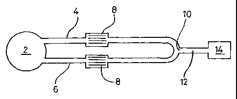
Figure 1 shows a device according to the invention. The device has a sample
application
region 2 fluidically connected to test flow path 4 and a reference flow path
6, which both
comprise a capillary channel. A filter 8 may optionally be provided in one or
both of the
flow paths. The flow paths converge downstream at a junction region 10 leading
to a
CA 02661065 2009-02-18
WO 2008/025945
PCT/GB2007/003091
13
common channel 12. An indicator region 14 may be provided downstream from the
junction region 10.
=
Liquid sample applied to the device via a sample application port in the
sample application
region 2 is able to flow respectively along the test and reference flow paths
4, 6 and
towards the junction region 10. One or more vents are provided in the common
channel
12 and the indicator region 14 to allow air to be displaced from the device by
the advance
of liquid along the capillaries. However, once one of the fluid fronts has
reached the
junction region 10, it blocks off the other flow path from the vents,
preventing further
advance of the liquid along the other flow path. Thus the device only allows
for the arrival
in the indicator region 14 of fluid flowing along the flow path whose fluid
front first
reaches the junction region 10. An indication means may be provided in the
fluid channels
to enable an observer to determine which fluid in the respective channel
arrived first. For
example dyes of different colours may be provided in each channel such that
the fluid
sample is able to interact with the dye to produce liquid of a particular
colour. Thus the
presence of a particular coloured dye in the indicator region would enable a
user to
determine which fluid reached the fluid gate first.
Preparation of the assay device according to Fig 1.
A base layer was prepared from agarose coated 200 m polyester (GelBond, BMA).
The
appropriate microfluidic features were cut out of a 751.1m thick heat sealing
adhesive PE
layers using a GraftTeC cutter and the two layers laminated together. Finally
a third layer
was laminated to the intermediate layer to provide microfluidic channels of
7511m.
Example 2
= An alternative embodiment of an assay device in accordance with the
invention is
illustrated in Figure 2. Components functionally equivalent to those of the
embodiment
illustrated in Figure 1 are denoted by common reference numerals.
As in the previous example, the assay device comprises a sample application
port in a
common sample application region 2, from which liquid sample can flow into a
capillary
CA 02661065 2009-02-18
WO 2008/025945
PCT/GB2007/003091
14
forming part of the test flow path 4 and a separate capillary forming part of
the reference
flow path 6. Alternatively each flow path may be provided with a unique,
separate sample
application region. Those skilled in the art will appreciate that the assay
device described
in the present examples may be provided with further test flow paths to test
for the
presence of further analytes of interest. The or each further test flow path
can, if desired,
be provided with a corresponding reference flow path.
In the embodiment depicted in Figure 2, each flow path comprises a filter
element 8 and an
indicator region 14, upstream of a junction region 10.
' 10
The filer element 8 comprises one or more binding partners for the analyte of
interest, in
this instance hCG. In the presence of the analyte of interest the binding
partner, particles
coated with anti-hCG monoclonal antibody, mediates an agglutination reaction.
Each flow path is also provided with a coloured dye which is mobilised by
contact, and
migrates, with the liquid sample.
The indicator region 14 of each flow path comprises a capillary channel
forming the word
"NOT" in the test flow path 4 and the word "PREGNANT" in the reference flow
path.
These capillaries are formed from clear synthetic plastics material and are
against a low
contrast background (e.g. white or clear synthetic plastics material).
Accordingly, prior to
performance of the assay, the capillaries are not highly visible.
However, once the assay is initiated, the dye located in the flow paths
upstream of the
indicator region is mobilised by the advancing liquid sample. If the sample
does not
contain hCG, liquid is free to flow along both flow paths. The dye-containing
liquid thus
fills both capillaries, displaying the assay result "NOT PREGNANT". Vents may
be
provided at several points along the reference flow path to encourage the flow
of liquid
therealong. In particular these vents may be provided to assist the liquid in
filling the
indicator region of the reference flow path. Preferably there are no such
vents in the test
flow path, air being vented from the test flow path capillary 4 only via one
or more vents
CA 02661065 2009-02-18
, WO 2008/025945 PCT/GB2007/003091
downstream of the junction region .10, in the common channel 12, such that if
liquid
flowing along the reference flow path 6 reaches the junction region 10 before
the, liquid
front flowing along the test flow path 4, air can no longer be displaced from
the test flow
path capillary and farther advance of the liquid along that channel is
prevented.
5
The rate of flow of liquid along the test and reference flow paths, and/or the
length of the
respective flow paths, is adjusted such that, in the absence of hCG, liquid
flows along both
flow paths 4, 6 and fills the respective indicator regions. Typically, in the
absence of hCG
in the sample, the liquid flowing along the reference flow path will reach the
junction
10 region 10 either simultaneously with the liquid flowing along the test
flow path or just 1 or
2 seconds in advance thereof.
If however the applied sample comprises hCG, agglutination will take place in
the test flow
path 4 which substantially retards the advance of liquid along the test flow
path capillary
15 towards the indicator region. This allows liquid flowing along the
reference flow path to
"win the race" to the junction region easily. The liquid flowing along the
reference flow
path reaches the junction region 10 before the liquid flowing along the test
flow path 4
reaches the indicator region. In this instance, the word "NOT" does not become
filled
with dye and remains indistinct, whilst the word "PREGNANT" becomes highly
visible
and thus displays the assay result.
Example 3
In order to provide a practical demonstration of the feasibility of the
invention 1541..cm
polystyrene beads (Polysciences) were coated with aminodextran 500,000 RMM,
then
with NHS-LCLC-Biotin to prepare biotinylated latex beads (NHS = N-hydroxy
succinimidyl, LCLC = "long chain", i.e. a 12 carbon spacer). Into 50 pi of a
200 g/m1
solution of BSA (to block non-specific binding sites), was added 50 Al of a 5%
solution of
the 15 Am biotin particles, mixed on a vortex. To the biotinylated particle
solution in
BSA, 5/11 of streptavidin li.tm magnetic particle in solution were added
solution, while
mixing on a vortex to prepare a test fluid. Immediately after preparation, the
fluid was
added to a microfluidic device as described below.
CA 02661065 2009-02-18
WO 2008/025945
PCT/GB2007/003091
16
A reference fluid consisting of BSA buffer was also prepared.
A microfluidic device was prepared having a sample application port provided
upstream
from a fluid channel of dimensions, 5mm wide by 3cm long by 100 m in height.
Provided
at a distance of 2cm along the fluid channel was a filter zone of 5inm in
length comprising
channels running parallel to the fluid channel having a 30 m gap.
Two such devices were prepared and a test solution and reference solution were
added
respectively to both and the time taken for the fluid front to reach the end
of the fluid
channel was measured. In this particular example, the test solution took 60s
to reach the
end of the channel. In contrast, the reference fluid took just 10s.
The delay in flow of the test fluid was due to the agglutinated particles
becoming stuck in
the filter zone. In the case of the reference fluid, no agglutination took
place and therefore
the fluid is able to flow unimpeded.