Note: Descriptions are shown in the official language in which they were submitted.
CA 02661152 2009-02-19
WO 2008/024375 PCT/US2007/018527
1
RESPIRATORY MUSCLE ENDURANCE TRAINING DEVICE AND
METHOD FOR THE USE THEREOF
CROSS-REFERENCE TO RELATED APPLICATION
[0001] This application claims the benefit of pending U.S. Application No.
60/839,040, filed August 21, 2006, the entirety of which is incorporated
herein by
reference.
TECHNICAL FIELD
[0002] The present disclosure relates generally to a training device, and in
particular, to a respiratory muscle endurance training device.
BACKGROUND
[0003] Patients with respiratory ailments, in particular patients with COPD
(Chronic Obstructive Pulmonary Disease), have impaired exercise tolerance and
diminished ventilatory efficiency. Various techniques have been developed to
improve respiratory muscle endurance capacity. For example, one technique
involves respiratory muscle training through the use of positive expiratory
pressure devices, such as the AEROPEP PLUS valved holding chamber available
from Trudell Medical International, the Assignee of the present application.
[0004] Another technique is referred to as Respiratory Muscle Endurance
Training (RMET). Most current RMET techniques require complicated and
expensive equipment, which limits widespread use. Alternatively, a portable
tube
has been developed for use by COPD patients, and has been effective in
improving
the endurance exercise capacity of the users.
SUMMARY
[0005] A respiratory muscle endurance training device includes a chamber and
a patient interface. One or both of a COZ sensor or a temperature sensor can
be
coupled to the chamber or patient interface to provide the user or caregiver
with
indicia about the COZ level in, or the temperature of, the chamber or patient
interface, and/or the duration of use of the device. In various embodiments,
one-
CA 02661152 2009-02-19
WO 2008/024375 PCT/US2007/018527
2
way inhalation and exhalation valves and fl ow indicators can also be
associated
with the chamber or patient interface.
[0006] In one aspect of the invention, a respiratory muscle endurance training
device includes a patient interface for transferring a patient's exhaled or
inhaled
gases and a fixed volume chamber in communication with the patient interface,
where the fixed volume chamber is sized to retain a portion of a patient's
exhaled
gases. A variable volume chamber in communication with the fixed volume
chamber, where the variable volume chamber is configured to be responsive to
the
patient's exhaled or inhaled gases to move from a first position to a second
position. A variable orifice may be positioned on the variable volume chamber
to
permit a desired amount of exhaled air to escape during exhalation and to
receive a
supply of air to replace the escaped exhaled air during inhalation.
(0007] Methods of using the device are also provided. In particular, the user
inhales and exhales into the chamber. Over the course of a plurality of
breathing
cycles, the COZ level in the chamber increases, thereby increasing the work of
breathing and exercising the user's lungs. In other embodiments, a visual or
audible indicator which may be located on the housing of the device may
provide
flashes or beeps, respectively, to prompt a patient to inhale or exhale at
each such =
indication. In yet other embodiments, a visual or audible indicator that is
separate
from the device may be used to assist a patient in establishing the desirable
breathing pattern.
[0008] The various embodiments and aspects provide significant advantages
over other respiratory muscle training devices. In particular, the training
device is
portable and the volume can be easily adjusted to accommodate different users,
for
example those with COPD, as well as athletes with healthy lungs. In addition,
the
user or care giver can quickly and easily assess the level or duration of use
by way
of various sensors, thereby providing additional feedback as to the proper use
of
the device.
[0009] The foregoing paragraphs have been provided by way of general
introduction, and are not intended to limit the scope of the following claims.
The
presently preferred embodiments, together with further advantages, will be
best
CA 02661152 2009-02-19
WO 2008/024375 PCT/US2007/018527
3
understood by reference to the following detailed description taken in
conjunction
with the accompanying drawings.
BRIEF DESCRIPTION OF THE DRAWINGS
[0010] FIG. 1 is a side view of one embodiment of a respiratory muscle
endurance training device. .
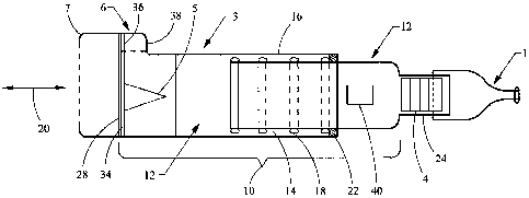
100111 FIG. 2 is a perspective view of an alternative embodiment of the
respiratory muscle endurance training device of FIG. 1.
[00121 FIG. 3 is a perspective view of the device of FIG. 2 during exhalation
with raised bellows.
[0013] FIG. 4 is a cross-sectional view of the device of FIG. 3 without a
flexible tube.
[0014] FIG. 5 is a top view of the device of FIGS. 2-3.
DETAILED DESCRIPTION
[0015] Referring to FIG. 1, a respiratory muscle endurance training device
includes a chamber 10, otherwise referred to as a spacer_ In one embodiment,
the
chamber includes a first chamber component 2 and a second chamber component
3. In other embodiments, the chamber 10 is formed as a single unitary
component.
The first and second chambers define an interior volume 12 of the chamber.
[0016] In one embodiment, mating portions 14, 16 of the first and second
chambers are configured as cylindrical portions or tubes, with the first
chamber
component 2 having an outer diameter shaped to fit within an inner diameter of
the
second chamber component 3. One or both of the chamber components are
configured with circumferential ribs 18 and/or.seals (shown in FIG. 1 on the
first
chamber component) that mate with the other chamber to substantially prevent
exhaled air from escaping from the chamber interface. In one embodiment, the
ribs 18 are spaced apart along the lengths of one or both of the chamber
components so as to allow the chambers to be moved longitudinally in a
longitudinal direction 20 relative to each other and then fixed at different
lengths
depending on the location of the ribs 18 and a mating shoulder 22 formed on
the
other chamber (shown in FIG. 1 as the second chamber component). The rings, or
CA 02661152 2009-02-19
WO 2008/024375 PCT/US2007/018527
4
ribs, and shoulder are preferably integrally molded with the chambers,
although
they can also be affixed separately, e.g., as an o-ring. It should be
understood that
various detent mechanisms, including springs, tabs, etc. can be used to index
the
first chamber component relative to the second chamber component. Of course,
it
should be understood that the chambers can also be infinitely adjustable
without
any set detents, for example with a simple friction fit between the chamber
components.
[0017] When adjusted, the overall interior volume 12 of the chamber 10 can be
adjusted. For example, the interior volume 12 of the chamber can be adjusted
from between about 500 cc to about 4000 cc. The chamber volume is adjusted
depending on various predetermined characteristics of the user, such as peak
expiratory flow. In this way, the interior volume 12 can be adjusted to reduce
or
increase the total exhaled volume of expired gases captured inside the chamber
10.
[0018] The first chamber component 2 includes an output end 24 that is
coupled to a patient interface 1. It should be understood that the terms
"coupling,"
"coupled," and variations thereof, mean directly or indirectly, and can
include for
example a patient interface in-molded with the first chamber at an output end
thereof. The patient interface can be configured, without limitation, as a
mask, a
mouthpiece, a ventilator tube, etc. The term "output" merely refers to the
fact that
gas or air moves through or from the chamber to the patient interface during
inhalation, notwithstanding that gas or air moves from the patient interface
into the
chamber during exhalation. The term "end" refers to a portion of the chamber
that
has an opening through which the gas or air moves, and can refer, for example,
to
a location on a spherical chamber having such an opening, with that portion of
the
sphere forming the "end."
[0019] The second chamber component 3 includes an input end 28, wherein air
or gas flows into the chamber 10. The chamber preferably includes a one-way
inhalation valve 5 that allows ambient air, or aerosol fr om an aerosol
delivery
device, to flow in a one-way direction through the input end 28 of the second
chamber component and into the interior volume 12. During an exhalation
sequence of the user, an exhalation valve 34 opens to allow exhaled gases to
escape to the ambient air. The inhalation valve 5 is preferably configured as
a
CA 02661152 2009-02-19
WO 2008/024375 PCT/US2007/018527
duck-bill valve, although other valves such as slit petal valves, center post
valves,
valves having a central opening with a peripheral sealing edge, etc. would
also
work. One acceptable valve is the valve used in the AEROPEP PLUS device,
available from Trudell Medical International.
[0020] The exhalation valve 34 is preferably formed around a periphery of the
inhalation valve. The second chamber 3 also includes a flow indicator 36,
formed
as a thin flexible member disposed in a viewing portion 38 formed on the
second
chamber, or as part of a valve cap 6. The flow indicator is configured to move
during inhalation or exhalation to provide indicia to the user or caregiver
that an
adequate flow is being generated in the device. Various embodiments of the
flow
indicator and inhalation and exhalation valves are disclosed for example and
without limitation in U.S. Patent No. 6,904,908, assigned to Trudell Medical
International; London, Ontario, Canada, the entire disclosure of which is
hereby
incorporated herein by reference. Examples of various aerosol delivery systems
and valve arrangements are disclosed in U.S. Pat. Nos. 4,627,432, 5,385,140
5,582,162, 5,740,793, 5,816,240, 6,026,807, 6,039,042, 6,116,239, 6,293,279,
6,345,617, and 6,435,177, the entire contents of each of which are
incorporated
herein by reference. A valve chamber 7 is coupled to the input end of the
second
chamber. The valve chamber isolates and protects the valves from being
contaminated or damaged, and further provides for coupling to a substance
delivery device such as a tube or an aerosol delivery device.
[0021] The chamber 10, for example the first chamber component 2 and/or the
patient interface 1, is configured with a CO2 sensor 4, for example and
without
limitation a CO2 Fenem colormetric indicator available from Engineering
Medical
Systems, located in Indianapolis, Indiana. The CO2 indicator 4 provides visual
feedback to the user and/or caregiver as to what the COZ level is in the
chamber
10, or the interior spaced defined by the chamber 10 and the patient interface
1, to
ensure that the CO21eve1 is sufficient to achieve the intended therapeutic
benefit.
As shown in FIG. 1, the sensor 4 is located at the output end of the chamber
10
adjacent the patient interface 1, or at the juncture of those components,
whether
formed integrally or separately. Of course, it should be understood that the
sensor
CA 02661152 2009-02-19
WO 2008/024375 PCT/US2007/018527
6
4 can be located directly-on or in the patient interface 1, or on or in either
of the
first and second chamber components 2, 3.
[0022] The expendable COZ indicator 4 is configured with user indicia to
indicate the level of CO2 in the chamber or interior. The indicator 4 includes
a
litmus paper with a chemical paper having a chemical material that reacts to
the
COZ concentration in a gas. For example and without limitation, the color
purple
indicates an atmospheric concentration of CO2 molecules less than 0.03%. The
color changes to a tan color at 2.0% CO2 in the gas. The color yellow
indicates
5.0% or more COZ concentration. At this level, the patient is re-inhaling
expired
gases (or dead space gases) to increase the concentration of COZ in the lungs
of the
user, which encourages the user to inhale deeper, thereby exercising the lung
muscles to expand beyond their normal condition. The sensor and indicator 4
can
be used to determine the CO2 level, or the length of the time the user has
been
using the device. After use, the indicator 4 holds the reading for a period of
time,
so that a caregiver who is temporarily absent can get a reading after the use
cycle
is completed. Eventually the indicator will reset.by returning to its
originalcolor
scheme, such that it can be used again. The device is compact and lightweight,
and is thus very portable.
[0023] The device can also be configured with a temperature sensor 40, such as
a thermochromic liquid crystals strip, available from Hallcrest Inc., Glenview
Illinois. The temperature sensor 40 is secured to the outside (or inside) of
one of
the chamber or user interface. A sensor can also be configured to measure the
actual gas/air temperature inside the chamber. In one implementation, the
temperature sensor 40 may utilize cholestric liquid crystals (CLC). The
temperature of the CLC is initially at room temperature. As the.user
successively
breathes (inhales/exhales) through the device, the CLC will expand and
contract
depending on the temperature. Depending on the temperature, the color of the
indicator will change, which also is indicative of, and can be correlated
with, the
length of time the user has been breathing through the device.
[0024] In one embodiment, an analog product line is used, which exhibits a
line that moves throughout the temperature cycle and provides a direct
correlation
to the elapsed time of use. The temperature indicator can be configured to
provide
CA 02661152 2009-02-19
WO 2008/024375 PCT/US2007/018527
7
for an indication of temperature at least in a range from room temperature to
slightly below the body temperature of the user, e.g., 37 degrees centigrade.
A
secondary temporal (e.g., minute) indicator can be located adjacent to the
temperature indicator to provide an indication of how long the user has been
using
the device, with the temperature being correlated with the elapsed time.
Again,
the indicator can be configured to hold a reading, and then reset for
subsequent
and repeated use.
[0025] The training device can be coupled to an aerosol delivery device (not
shown), such as a nebulizer or metered dose inhaler, to deliver medication to
the
user through the chamber and patient interface. In this way, the device
performs
two (2) functions, (1) respiratory muscle endurance training and (2) treatment
for
respiratory ailments or diseases such as COPD or asthma. In one embodiment,
the
metered dose inhaler is engaged through an opening formed in the valve chamber
7.
[0026] The materials used to manufacture the device may be the same as those
used to make the AEROCHAMBER holding chambers available from Trudell
Medical International of London, Ontario, Canada, which chambers are disclosed
in the patents referenced and incorporated by reference above. The diameter of
the chambers 10, 2, 3 can range from between about 1 inch to about 6 inches.
Although shown as cylindrical shapes, it should be understood that other cross-
sectional shapes would also be suitable, including elliptical and rectangular
shapes, although for devices also used for aerosol delivery, a cylindrical or
elliptical shape is preferred to minimize impaction and loss of medication
prior to
reaching the patient.
[0027] An alternative embodiment of a respiratory muscle endurance training
(RMET) system 50 is illustrated in FIGS. 2-5. In this embodiment, a tube 52 is
connectable with a chamber which may have a fixed volume portion.54 defined by
a housing 56. A flexible bellows 58 defines an adjustable volume portion 60.
The -
tube 52 may be of a diameter ranging from 22 mm to 40 mm that provides a dead
space volume (also referred to as rebreathing gas) of between 10 cubic
centimeters
(cc) to 40 cc per inch. The length may be varied between 10 inches to 36
inches in
one embodiment. The tube 52 may be corrugated tubing made of polyvinyl
CA 02661152 2009-02-19
WO 2008/024375 PCT/US2007/018527
8
chloride (PVC) and have markings every six inches for reference when cutting
to a
desired length. The fixed volume portion 54 defined by the housing 56 may be
manufactured in two sections to enclose 1600cc, however it may also be
produced
to have a volume in a range from 500 cc to 1600 cc in order to cover an
expected
range of patients from the small and thin to the large or obese.
[00281 The housing 56 may be constructed from a polypropylene material or
any of a number of other molded or formable materials. The housing may be
manufactured in two halves 55, 57 that are friction fit together, glued,
welded or
connected using any of a number of know connection techniques. Also, the
housing 56 may be fashioned in any of a number of shapes having a desired
fixed
volume. Hand rests 59, which may also be used as device resting pads, may be
included on the housing 56. The bellows 58 may be manufactured from a silicone
or other flexible material and connected with the housing 56 at a seal defined
by a
rim 62 on the housing 56 and a receiving groove 64 on the end of the bellows
58
that is sized to sealably grip the rim 62. In other embodiments, the bellows
may
be replaced with a balloon or other expandable body suitable for accommodating
variable volumes. In the implementation of FIGS. 2-4, the housing 56 may have
a
diameter of 6 inches and a height of 3.5 inches. Other sizes may be fabricated
depending on the desired volume of gases.
[0029] As best shown in FIG. 2, the bellows 58 may be contained within the
housing 56 when no breathing is taking place using the system 50. FIGS. 2-3
illustrate the RMET system 50 with the bellows extended as a patient exhales.
A
volume reference member 66 having a scale 68 applied thereto or embedded
therein may be mounted on the housing 56. The scale may be a linear scale such
as a scale indicating increments of cc's, for example 100 cc increments from 0
to
500 cc. In one embodiment, the volume reference member 66 is foldable against
the housing 56 by hinges 67 on the housing to permit a compact profile when
not
in use. An indicator 70 connected with the bellows 58 moves with the bellows
58
during breathing so that its position adjacent the volume reference member 66
on
the housing 56 will provide information relating to the volume for each
patient
breath. FIG. 2 illustrates the RMET system 50 when the bellows 58 are fully
CA 02661152 2009-02-19
WO 2008/024375 PCT/US2007/018527
9
retracted, such as when the device is at rest or a patient is inhaling. FIGS.
3-4
illustrate the system 50 with bellows 58 extended during patient exhalation.
[0030] The cap 74 on the bellows 58 defines a variable orifice 72 which may
control the upper movement of the bellows 58 and defme the final volume of the
adjustable volume portion 60. The variable orifice 72 is set to allow excess
exhaled gases to depart from the system to help prevent the patient from
inhaling
more than a desired percentage of the exhaled gases. In one embodiment, 60% of
exhaled gases are desired for inhalation (rebreathing). In the RMET system 50
of
FIGS. 2-4, the variable orifice 72 also acts to allow fresh, inspired gases to
enter
into the system 50 when the patient inhales more than the volume contained in
the
system 50. In this manner, the additional 40% of gases necessary after the 60%
of
exhaled gases have been inhaled may be breathed in_ Preferably, there are no
valves in the variable orifice 72 in order to allow the gases to flow freely
through
the system. By adjusting the resistance of the variable orifice 72 to flow on
exhalation, the height of the bellows is adjusted during exhalation and the
desired
mix of exhaled and fresh gases may be selected (in this example 60/40).
[0031] Referring to FIGS. 4-5, the variable orifice 72 may be formed by
overlapping portions, where an upper portion 76 has an opening 84 that may be
rotated with respect to an underlying portion 78 to selectively expose all or
a
portion of one or more openings 86 in the underlying portion. The variable
orifice
72 may be adjusted by pushing against grips 80 extending out from the upper
portion so that the upper portion will rotate about a central axis. By pushing
against the grips 80 and turning the upper portion 76 with respect to the
lower
portion 78 about a central axis 82, the opening 84 in upper portion 76 may be
aligned with one or more openings 86 iri the lower portion 78. Although a
rotatable arrangement is illustrated, other arrangements to vary an opening
size are
contemplated.
[0032] In operation, a patient first exhales into the patient interface, which
may
be a mouthpiece 53, mask or other interface on the end of the corrugated
tubing
52. Upon the subsequent inhalation, the patient will inhale expired gases
located
in the corrugated tubing 52, the fixed volume portion 54 and the adjustable
volume
portion 60, in addition to any additional fresh gas (such as ambient air)
entering
CA 02661152 2009-02-19
WO 2008/024375 PCT/US2007/018527
into the system through the variable orifice 72 on the flexible bellows 58.
The
amount of exhaled gases may be set to be approximately 60% of the maximum
voluntarily ventilation (MVV). To calculate how the level of ventilation may
be
set to approximately 60% of MVV, one may multiply 35 x FEV 1(forced
expiratory volume in the first second). This results in the relationship of
60%
MVV = 0.6 x 35 x FEV 1. The dead space of the RMET system 50, in other words
the amount of volume for holding exhaled gases, may be adjusted to 60% of the
patient's inspiratory vital capacity (IVC). The breathing pattern of the
patient
must be set above the normal breaths per minute, which is generally 12 to 15
breaths per minute. A breathing pattern between 16 to 30 breaths per minute
may
be suitable depending on the patient. In the embodiments as described herein,
the
breathing pattern is preferably 20 breaths per minute. The embodiments as
described herein may comprise a visual or audible indicator to assist the
patient in
establishing the desirable breathing pattern. For example, where the desired
breathing pattern is 20 breaths per minute a visual indicator, such as a
light, would
flash on and off every 3 seconds prompting the patient to inhale every time
the
light is on or every time the light turns off. The visual or audible indicator
could
be located adjacent the volume reference member 66. Although a mouthpiece 53
may be directly connected with the housing 56 as shown in FIG. 4, the tubing
52
shown in FIGS. 2-3 permit greater flexibility in customizing the amount of
exhaled air retained in the system 50.
[0033] Assuming that, on average, a COPD patient's IVC is approximately 3.3
liters, 60% of 3.3 liters is approximately 2 liters. To achieve this capacity
with the
RMET system 50, an accumulation of a fixed volume plus a variable volume is
used. The fixed volume with a flexible tubing 52 (120 cc to 240 cc) plus a
fixed
volume portion 54 of 1600cc defined by the housing 56, along with a bellows 58
adjustable between approximately 0 cc to 400 cc accounts for the 60% of the
IVC.
During exhalation, 40% of the expired volume of gases may be expelled through
the variable orifice 72 in the bellows 58. During inhalation, the patient may
inhale
the exhaled volume of gases in the system 50 and inhale the remaining 40% of
gases necessary to complete the IVC through the variable orifice 72 on the
bellows
CA 02661152 2009-02-19
WO 2008/024375 PCT/US2007/018527
11
58. To adjust the volume of expired gases collected from the patient, it is
possible
to reduce the length of the corrugated tube and reduce the fixed volume of gas
in
the device.
[0034] The patient observes the movement of the indicator 70 against the scale
68 on the housing to determine that the 60% volume of the patient's NC has
been
reached. A separate or integrated timing device (not shown), such as a
mechanical
or electronic timer emitting an audible and/or visible signal, can assist the
patient
to perform a breathing program at a sufficient rate of breaths per minute. It
is
contemplated that the initial setting of the RMET system 50 to 60% of a
patient's
specific NC may be made by a caregiver. The caregiver or patient may, for
example, use a pulmonaryfunction machine to determine the patient's FEV 1
which can then be used to calculate the patient's MVV and ultimately 60% of
the
IVC.
[0035] Although the present invention has been described with reference to
preferred embodiments, those skilled in the art will recognize that changes
may be
made in form and detail without departing from the spirit and scope of the
invention. As such, it is intended that the foregoing detailed description be
regarded as illustrative rather than limiting and that it is the appended
claims,
including all equivalents thereof, which are intended to define the scope of
the
invention.