Note: Descriptions are shown in the official language in which they were submitted.
CA 02661745 2009-02-24
WO 2008/024908 PCT/US2007/076636
-1-
SYSTEM AND METHOD FOR IMPROVED LOW FLOW MEDICAL PUMP
DELIVERY
DESCRIPTION
CROSS-REFERENCE TO RELATED APPLICATIONS
[0001] This application is a continuation-in-part of U.S. Patent Application
Serial
No. 10/810,123, filed March 26, 2004.
FEDERALLY SPONSORED RESEARCH OR DEVELOPMENT
[0002] None.
TECHNICAL FIELD
[0003] The invention relates to medical pumps for delivering a substance, such
as
a fluid to a patient. In particular, the present invention relates to medical
pumps
which provide low flow delivery of a substance to a patient.
BACKGROUND OF THE INVENTION
[0004] Modern medical care often involves the use of medical pump devices to
deliver substances, such as fluids and/or fluid medicine to patients. Medical
pumps
permit the controlled delivery of substances to a patient, and such pumps have
largely
replaced gravity flow systems, primarily due to the pump's much greater
accuracy in
delivery rates and dosages, and due to the possibility for flexible yet
controlled
delivery schedules.
[0005] A typical positive displacement pump system includes a pump device
driver and a disposable fluid or pumping chamber, defined in various forms
including
but not limited to a cassette, syringe barrel or section of tubing. A
disposable cassette,
which is adapted to be used only for a single patient and for one fluid
delivery round,
is typically a small plastic unit having an inlet and an outlet respectively
connected
through flexible tubing to the fluid supply container and to the patient
receiving the
fluid. The cassette includes a pumping chamber, with the flow of fluid through
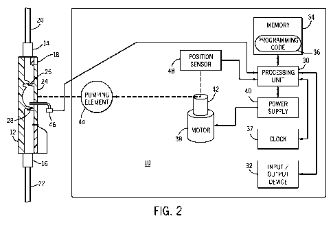
the
chamber being controlled by a plunger or pumping element activated in a
controlled
manner by the device driver.
[0006] For example, the cassette chamber may have one wall or wall portion
formed by a flexible, resilient diaphragm or membrane that is reciprocated by
the
CA 02661745 2009-02-24
WO 2008/024908 PCT/US2007/076636
-2-
plunger and the driver to cause fluid to flow. The pump driver device includes
the
plunger or pumping element for controlling the flow of fluid into and out of
the
pumping chamber in the cassette, and it also includes control mechanisms to
assure
that the fluid is delivered to the patient at a pre-set rate, in a pre-
determined manner,
and only for a particular pre-selected time or total dosage.
[0007] The fluid enters the cassette through an inlet and is forced through an
outlet under pressure. The fluid is delivered to the outlet when the pump
plunger
forces the membrane into the pumping chamber to displace the fluid. During the
intake stroke the pump plunger draws back, the membrane covering the pumping
chamber pulls back from its prior fully displaced configuration, and the fluid
is then
drawn through the open inlet and into the pumping chamber. In a pumping
stroke, the
pump plunger forces the membrane back into the pumping chamber to pressurize
and
force the fluid contained therein through the outlet. Thus, the fluid flows
from the
cassette in a series of spaced-apart pulses rather than in a continuous flow.
[0008] One of the requirements for a medical pump is that it is able to
deliver
precise volumes at precise delivery rates. Conventional pumps, in general,
rely on
nominal or empirical data to estimate the delivery volumes and delivery rates,
and do
not provide mechanisms for adjusting an actual delivery due to variations from
this
nominal or empirical data. This lack of adjustment during an actual delivery
limits
the accuracy and/or flow continuity of these pumps.
[0009] In addition, medical pumps are operated at low flow rates, such as
below 1
mL/hr or less, the determination of when the medical pump is actually
delivering a
substance to a patient can be difficult. It has been found that sensed data
can provide
false indications that actual delivery of the substance, such as the flow of a
fluid, is
occurring. In fact, it has been determined that sensed data indicating that
delivery of
the substance has begun can actually be attributed to leakage or some other
reason, as
suggested by the sensed data, such as pressure, instead of the delivery
actually
beginning. Other potential difficulties occur when attempting to use
traditional
medical pumps at low flow rates, without using specialty items such as
specialty
neonatal cassettes. In particular, mechanical friction and/or electrical noise
can also
trigger false data indicating that the delivery has actually begun, inducing
periods of
no flow. This friction and/or noise can be attributed to many things,
including but not
limited to the cassette diaphragm, the plunger tip finish, and/or the plunger
body O-
rings to internal bearing pressure / force sensor flex bias.
CA 02661745 2009-02-24
WO 2008/024908 PCT/US2007/076636
-3-
[0010] Thus, it is a principal object of this invention to provide a medical
pump
and a method of operating a medical pump to overcome these deficiencies and
accurately deliver a substance to a patient, such as an infant, in smaller
increments for
low flow rates in a more continuous manner (known as Low Flow Continuity). In
general, Low Flow Continuity is defined as the ability of a pump to deliver at
rates of
1 ml/hr to 0.1 ml/hr or less with periods of "no-flow" not exceeding 20
seconds and
bolus volumes not exceeding 2 micro-liters. To meet the highest Emergency Care
Research Institute (ECRI) industry standards for Low Flow Continuity and
achieve an
"Excellent" ECRI rating, the pump must at least deliver fluid in increments no
greater
than two micro-liters at a flow rate of 0.1 milliliter per hour with a maximum
"no-
flow" period of 20 seconds.
[0011] The present invention is provided to solve the problems discussed above
and other problems, and to provide advantages and aspects not provided by
prior
medical pumps. A full discussion of the features and advantages of the present
invention is deferred to the following detailed description, which proceeds
with
reference to the accompanying drawings.
SUMMARY OF THE INVENTION
[0012] The present invention is directed to a medical pump with an improved
continuity low flow delivery system and method, for use with a pumping
chamber, for
example in a cassette, is disclosed. The pump includes a pump drive for
exerting a
force on the pumping chamber and a sensor for sensing the force/pressure
exerted by
the pump drive on the pumping chamber. A pump drive position sensor can also
sense the position of the pump drive. The medical pump includes a processing
unit
and a memory having a programming code adapted to calculate the rate of change
of
the sensed force/pressure values and determine whether the rate of change of
the
sensed force/pressure values meets a rate of change threshold. Once the rate
of
change threshold is met, the programming code is adapted to calculate a
remaining
pump drive travel value, such as a linear distance, an angular distance, or a
time, for
determining how much farther the pump drive should travel before the end of an
effective pump cycle. The programming code is further adapted to trigger one
or
more signals to drive the pump drive for the remainder of the effective pump
cycle
using the remaining pump drive travel value.
CA 02661745 2009-02-24
WO 2008/024908 PCT/US2007/076636
-4-
[0013] In one embodiment, the pump drive of the medical pump includes a
stepper motor. In an alternative embodiment, the pump drive includes a direct
current
motor. Either embodiment can be arranged to drive the motor in a constant
speed
arrangement or in a variable speed arrangement. The programming code is
further
adapted to calculate an estimated incremental delivery volume. The medical
pump
can also include a pumping element, and the pump drive drives the pumping
element
for exerting a force on the pumping chamber.
[0014] In a particular embodiment, the pump drive drives a cam which drives a
plunger for exerting a force/pressure within a pumping chamber. In such an
embodiment, the medical pump will operate in cycles, each of which is
separated into
three phases. The first phase is a pressurization phase wherein the pump drive
drives
a cam which causes the plunger to exert a force to the pumping chamber of the
cassette until the outlet valve of the pumping chamber "cracks" and begins
effective
delivery of the substance. As will be explained in detail below, the medical
pump
prevents false detection of pump chamber "cracking" and makes particular
determinations and calculations based on accurate detection of when effective
delivery is actually occurring, so as to provide continuity at low flow
delivery rates.
In this embodiment, the second phase begins when effective delivery begins,
and
thereby the pump begins to release a bolus volume of the substance. The
stepper
motor then steps through a calculated number of delivery steps according to a
calculated time for such step until effective delivery is complete for the
cycle. Once
effective delivery is completed, retraction phase begins, wherein the pump
drive
drives the cam to cause the plunger to retract from applying pressure on the
pumping
chamber. The pumping chamber then expands and draws more substance into the
pumping chamber for the next cycle. When retraction is complete, the cycle is
complete and the next cycle is ready to begin.
[0015] In one embodiment, the medical pump continuously detects the position
of
the pump drive and determines a cycle start position from this position
information.
The medical pump drives the pump drive at a drive rate which is based on a
desired
delivery rate, and senses a plurality of force/pressure values using the
force/pressure
sensor, which are representative of the force/pressure exerted on the
force/pressure
sensor as the driving of the pump drive occurs. The programming code is
adapted to
calculate the rate of change of the sensed force/pressure values, and
determine in a
first determination step whether the rate of change of the sensed
force/pressure values
CA 02661745 2009-02-24
WO 2008/024908 PCT/US2007/076636
-5-
meets a first rate of change value or threshold. If the first determination
step is true,
the programming code is further adapted to determine in a second determination
step
whether the rate of change of the sensed force/pressure values meets a second
rate of
change value or threshold. If the second determination step is true, the
programming
code is further adapted to calculate a remaining pump drive travel value for
determining how much farther the pump drive should travel before the end of an
effective pump cycle, and cause the pump to complete the effective pump cycle
delivery using the remaining pump drive travel value.
[0016] In another embodiment, the medical pump calculates the remaining pump
drive travel value by having effective cycle travel value information and
determining
an already traveled cycle value by using the continuous detection of the
position of
the pump drive and using this position information when the second
determination
step is true. The programming code is adapted to calculate the remaining pump
drive
travel value by subtracting the already traveled cycle value from the
effective cycle
travel value. When a stepper motor is used, once the remaining pump drive
travel
value is determined, a pump drive step value to complete the effective cycle
can be
determined by dividing the remaining pump drive travel value by a step travel
size
value.
[0017] In one embodiment, the first and second rate of change values are both
predetermined values, such as a set amount of change in force per time. In
addition,
the first determination step can determine whether the rate of change of the
sensed
force/pressure values is greater than the first rate of change value, and the
second
determination step can determine whether the rate of change of the sensed
force/pressure values is less than a second rate of change value. In various
embodiments, the first rate of change value can be equal to, less than, or
greater than
the second rate of change value. In another embodiment, the first and second
rate of
change values can be calculated, such as for each cycle. One example of this
calculation is using a predetermined percentage of a highest rate of change
value from
a previous cycle.
[0018] The medical pump can prevent the detection of false effective delivery
occurring in various ways, as indicated above. The medical pump can also
perform
this function by determining whether the pump drive has traveled beyond a
minimum
allowable pump drive travel value for a cycle. A medical pump can also
determine
whether the pump drive has traveled beyond a maximum allowable pump drive
travel
CA 02661745 2009-02-24
WO 2008/024908 PCT/US2007/076636
-6-
value for a cycle. The medical pump can further calculate an average
force/pressure
value for each of a plurality of time intervals, and use the averaged
force/pressure
values to determine the rate of change of the sensed force/pressure values,
instead of
using directly sensed values to perform at least the threshold determination
steps.
[0019] To prevent false detection of when effective delivery begins, the
medical
pump can additionally or alternatively determine whether a predetermined
initial
travel value, such as a linear distance, an angular distance, or a time, has
been met in
relation to the cycle start position such as a linear distance, an angular
distance, or a
time. Once this value has been met, the medical pump can prevent the above
first
determination step from occurring, prevent the above step of sensing the
plurality of
force/pressure values, and/or prevent the above step of calculating the rate
of change
of the sensed force/pressure values. Alternatively or in addition to the above
prevention techniques, the medical pump can determine whether an additional
travel
value has been met after the above first determination step is true. If so,
the medical
pump can prevent the above second determination step from occurring, prevent
the
above step of sensing the plurality of force/pressure values, and/or prevent
the above
step of calculating the rate of change of the sensed force/pressure values.
[0020] As an example of one of the further effective delivery detection
techniques, the medical pump determines a cycle start position, drives the
pump drive
at a drive rate which is based on a desired delivery rate, senses a plurality
of
force/pressure values over time using the force/pressure sensor, which are
representative of the force/pressure exerted on the force/pressure sensor as
the driving
of the pump drive occurs, determines whether a predetermined initial travel
value has
been met in relation to the cycle start position, and calculates the rate of
change of the
sensed force/pressure values. However, the medical pump prevents sensing the
plurality of force/pressure values and/or calculating the rate of change of
the sensed
force/pressure values until a predetermined initial travel value has been met.
The
medical pump determines whether the rate of change of the sensed
force/pressure
values is less than a threshold rate of change value, and if the rate of
change of the
sensed force/pressure values is less than the threshold rate of change value,
the
medical pump calculates a remaining pump drive travel value for determining
how
much farther the pump drive should travel before the end of an effective pump
cycle.
The medical pump then completes the effective pump cycle delivery using the
remaining pump drive travel value.
CA 02661745 2009-02-24
WO 2008/024908 PCT/US2007/076636
-7-
[0021] In a further example, if the rate of change of the sensed
force/pressure
values has met the threshold rate of change value, then the medical pump
determines
whether a predetermined further travel value has been met, and drives the pump
drive
based on the predetermined further travel value. If the predetermined further
travel
value has been met and/or fulfilled, then the medical pump calculates a
remaining
pump drive travel value for determining how much farther the pump drive should
travel before the end of an effective pump cycle. The medical pump then
completes
the effective pump cycle delivery using the remaining pump drive travel value.
[0022] In one particular embodiment, such as a syringe pump, the pump
determines the delivery cycle start position and determines the amount, such
as a
weight or a volume, of a substance remaining to be delivered. The medical pump
drives the pump drive at a drive rate which is based on a desired delivery
rate, senses
a plurality of force/pressure values over a travel distance using the
force/pressure
sensor, which are representative of the force/pressure exerted on the
force/pressure
sensor as the driving of the pump drive occurs, and determines the rate of
change of
the sensed force/pressure values over the travel distance. The medical pump
also
determines in a first determination step whether the rate of change of the
sensed
force/pressure values meets a first rate of change value, and if the first
determination
step is true, determines whether the amount of the substance remaining to be
delivered
has changed. If the amount of the substance remaining to be delivered has
changed
more than a change threshold, the medical pump completes the delivery cycle.
If the
amount of the substance remaining has not changed more than a change
threshold, the
medical pump considers that no effective delivery has occurred in one or more
steps
or movements, and considers that some form of "sticking" is taking place. In
order to
unstick one or more of the moving parts of the medical pump, the medical pump
can
drive the pump drive in a reverse direction for unsticking the substance
delivery.
Additional successive forward and then reverse movements of the pump drive can
be
performed, which can be referring to as "dithering," in order to unstick the
delivery.
[0023] In one embodiment, the pumping chamber formed from a line, such as a
tube segment, and a plurality of pumping elements, such as fingers, are
provided for
exerting a pressure / force on the line and the pumping chamber, such as
within a
peristaltic medical pump. The arrangement and process steps of the prior
embodiments equally apply to this embodiment, which one of ordinary skill in
the art
CA 02661745 2009-02-24
WO 2008/024908 PCT/US2007/076636
-8-
would understand from review of the above embodiments, below description, and
drawings.
[0024] One advantage of the present system and method is that the ECRI
requirements for an "Excellent" rating are achieved. Specifically, the medical
pump
delivers a substance in increments or bolus volumes of no greater than two
micro-
liters at a flow rate of 0.1 milliliter per hour, with "no-flow" periods of
less than 20
seconds f Another advantage of the present invention is that each step of the
delivery
of the substance is consistent within a small error margin.
[0025] Other features and advantages of the invention will be apparent from
the
following specification taken in conjunction with the following drawings.
BRIEF DESCRIPTION OF THE DRAWINGS
[0026] To understand the present invention, it will now be described by way of
example, with reference to the accompanying drawings.
[0027] FIG. 1 is an illustration of one embodiment of the medical pump of the
present invention.
[0028] FIG. 2 is an illustration of another embodiment of the medical pump of
the
present invention.
[0029] FIG. 3 is a flow chart of one method of operating one embodiment of the
medical pump of the present invention.
[0030] FIG. 4 is a graph of the sensed force / pressure values over time as
well as
the change in sensed force / pressure values over time for one embodiment of
the
medical pump of the present invention.
[0031] FIG. 5 is a graph of the change in the sensed force / pressure values
over a
pump drive travel angle for one embodiment of the medical pump of the present
invention.
[0032] FIG. 6 is a graph of the change in the sensed force / pressure values
over a
pump drive travel angle for one embodiment of the medical pump of the present
invention, after a filtering step is performed.
[0033] FIG. 7 is a concurrent graph of no flow delivery performance and bolus
delivery performance of the embodiment of FIG. 2 at a first low flow delivery
rate.
[0034] FIG. 8 is a concurrent graph of no flow delivery performance and bolus
delivery performance of the embodiment of FIG. 2 at a second low flow delivery
rate.
CA 02661745 2009-02-24
WO 2008/024908 PCT/US2007/076636
-9-
[0035] FIG. 9 is an illustration of another embodiment of the medical pump of
the
present invention.
[0036] FIG. 10 is a graph of the sensed applied force / pressure over pump
motor
drive travel for the embodiment of FIG. 9, depicting normal operation.
[0037] FIG. 11 is a graph of the sensed applied force / pressure over pump
motor
drive travel for the embodiment of FIG. 9, depicting an unsticking operation.
[0038] FIG. 12 is a concurrent graph of no flow delivery performance and bolus
delivery performance of the embodiment of FIG. 9 at a first low flow delivery
rate.
[0039] FIG. 13 is a concurrent graph of no flow delivery performance and bolus
delivery performance of the embodiment of FIG. 9 at a second low flow delivery
rate.
[0040] FIG. 14 is an illustration of further embodiment of the medical pump of
the present invention.
DETAILED DESCRIPTION
[0041] While this invention is susceptible of embodiments in many different
forms, there is shown in the drawings and will herein be described in detail
preferred
embodiments of the invention with the understanding that the present
disclosure is to
be considered as an exemplification of the principles of the invention and is
not
intended to limit the invention to the embodiments illustrated.
[0042] A medical pump includes but is not limited to enteral pumps, infusion
pumps, cassette pumps, syringe pumps, peristaltic pumps, or any positive
displacement fluid pumping device for the delivery of fluids intravenously or
intra-
arterially to a patient. Referring initially to FIG. 1, one embodiment of a
medical
pump 10 is provided in connection with a disposable pumping chamber, such as a
cassette 12 or tube, for delivering a substance, such as a fluid, to a
patient. In various
embodiments of the medical pump of the present invention, the pumping chamber
is a
portion of at least one of a cassette, a tube, and/or a syringe, depending on
the type of
medical pump. The medical pump 10 provides a mechanism for adjusting an actual
delivery of the substance based on variations from nominal data used to
estimate
pump performance. A processing unit 30 is included in pump 10 and performs
various operations described in greater detail below. An input/output device
32
communicates with the processing unit 30 and allows the user to receive output
from
processing unit 30 and/or input information or commands into the processing
unit 30.
Those of ordinary skill in the art will appreciate that input/output device 32
may be
CA 02661745 2009-02-24
WO 2008/024908 PCT/US2007/076636
-10-
provided as a separate display device and/or a separate input device. A memory
34
communicates with the processing unit 30 and stores code and data necessary
for the
processing unit 30 to calculate and output the operating conditions of pump
10. The
memory 34 stores a programming code 36 formed in accordance with the present
invention for processing data to determine and control the operating condition
of the
pump 10. A clock 37 is used to keep time in the pump 10. The clock 37 is
connected
to the processing unit 30, and provides the processing unit 30 with time
information
for correlating data over time or conducting time sensitive activities. An
electric
motor 38 is controlled by processing unit 30 and is energized by a power
supply 40 to
serve as a prime mover for rotatably driving a shaft 42 connected to the motor
38.
The processing unit 30 orders the motor 38 to run at a constant speed or at
different
speeds, depending on the motor being used and depending on the flow rate
desired
through the pump 10. The down-stroke or delivery portion of the stroke has the
motor
38 running directly from power supply 40. The up-stroke, retract or fill
portion of the
stroke is run at a voltage set by the processing unit 30, so that the retract
times are
varied by the processing unit 30, where higher desired flow rates require
faster retract
speeds. A pumping element 44, such as a plunger, is operatively associated
with the
shaft 42. When energized, the pumping element 44 reciprocates back and forth
to
periodically down-stroke, causing pumping element 44 to press on pumping
chamber
24, and expel fluid therefrom. On an up-stroke, pumping element 44 releases
pressure
from pumping chamber 24 and thereby draws fluid from inlet port 14 into
pumping
chamber 24. Thus, the pumping element 44 intermittently pressurizes the
pumping
chamber 24 during a pumping cycle. The power supply 40, the motor 38, and/or
the
pumping element 44 together, alone, or in some combination thereof, may be
considered a pump drive for the purposes of the present specification. Other
parts
and/or elements may also make up the pump drive, as one of ordinary skill in
the art
would understand. In addition, parts of each of the power supply 40, the motor
38,
the pumping element 44, and/or other elements can make up what is referred to
herein
as the pump drive, with the understanding that the pump drive is controlled by
the
processing unit 30 for driving the delivery of the substance to the patient
through the
use of the pumping chamber.
[0043] A force/ pressure sensor 46 is operatively associated with the pumping
element 44 to detect the force or pressure exerted by the pumping element 44
on the
pumping chamber 24. As shown in FIG. 1, the sensor 46 can be directly
connected to
CA 02661745 2009-02-24
WO 2008/024908 PCT/US2007/076636
-11-
the pumping element and positioned in-line with the pumping element 44,
between
the pumping chamber 24 and the shaft 42 of the motor 38. In this embodiment,
the
sensor 46 is the only force / pressure sensor included in the medical pump 10,
and
operates to sense the force / pressure on pumping element 44 as well as to
generate a
force / pressure signal based on this force / pressure. The force / pressure
sensor 46 is
in electronic communication with the processing unit 30 to send the force /
pressure
signal to the processing unit 30 for use in determining operating conditions
of pump
10. One of ordinary skill in the art will appreciate that the pressure sensor
46 may be
a force transducer, strain gauge, or any other device that can operatively
sense the
pressure or related force brought to bear on the pumping chamber 24 by pumping
element 44.
[0044] A position sensor 48 is operatively associated with the pumping element
44 to directly or indirectly detect the position of the pumping element 44.
The
position sensor 48 tracks each pumping cycle of pump 10 by detecting the
position of
the pumping element 44 at each position within each cycle. As shown, the
position
sensor 48 is associated with the shaft 42. The position sensor 48 generates a
pump
drive travel signal by detecting the rotational position of the shaft 42. The
position
sensor 48 is in electronic communication with the processing unit 30 to send
the
position signal to the processing unit 30. The processing unit 30 utilizes
this
information in various ways as will be described in greater detail below. One
way
includes associating the incoming force / pressure data with a particular
travel value
within the pumping cycle, such as a time, a linear distance, and/or rotational
distance
or angle of travel. One of ordinary skill in the art will appreciate that the
position
sensor 48 could alternatively track a cam attached to the shaft 42 or the
pumping
element 44. Additionally, one of ordinary skill in the art will appreciate
that the
position sensor 48 as used herein includes but is not limited to mechanical
indicators,
such as pivoting dial indicators, electronic switches, Hall Effect sensors,
and optical
based position detectors. The resolution of the position sensor 48 assists in
achieving
improved continuity, as will be better understood from the below description.
In low
friction pumping systems, finer pump drive step sizes and higher resolution
pump
drive position sensors 48 can be used. In one embodiment, the pump drive
position
sensor 48 has a resolution of about 0.35 mils for a 0.1 mL/hr. delivery rate.
It has
been determined that resolutions from at least about 0.15 mils can induce
rates as low
as 0.04mL/hr. and still meet the "Excellent ECRI low flow continuity" rating.
The
CA 02661745 2009-02-24
WO 2008/024908 PCT/US2007/076636
-12-
step size is selected as a function of the desired delivery rate, and values
anywhere
between 0.15 and 0.45mils will provide significant continuity improvements for
rates
between 0.04 and 1.OmL/hr.
[0045] In a preferred embodiment, the motor 38 is a brush DC motor with a 128
count magneto-resistive encoder that is used in quadrature, for a total
resolution of
512 counts per motor revolution. Depending on the number of motor shaft 42
rotations needed to perform a pump cycle, the cycle can be divided into a very
fine
number of positions. For example, if it takes 10 rotations of the pump shaft
42 to
complete one pumping cycle or stroke (360 degrees in one embodiment), each
cycle
can be separated into 5120 travel positions or values. Thus, in this example,
the
position sensor 48 can provide information which allows for a resolution of
5120
travel positions per cycle for the processing unit 30 to determine and/or
utilize within
other calculations and determinations. One such motor is made by Portescap (a
Danaher company), under model number 16G88.214E, MR128, B1627:1. The use of
this or similar motors will be described in greater detail below.
[0046] Referring to FIG. 2, a similar arrangement is shown as FIG. 1. However,
a
specific cassette 12 is depicted with the internal construction of the
cassette 12 shown.
As also shown in FIG. 1, the cassette 12 may include an inlet 14 and an outlet
16
formed in main body 18. An inlet fluid line 20 couples the inlet port 14 on
the main
body 18 to a fluid source such as an IV bag or other fluid container.
Similarly, an
outlet fluid line 22 couples the outlet port 16 on main body 18 to the body of
a patient.
As shown in FIG. 2, an inlet valve 26 and outlet valve 28 are located within
the main
body 18. The pumping chamber 24 is connected in fluid flow communication
between the inlet port 14 and the outlet port 16. The pumping chamber 24
operates to
meter fluid through the cassette 12. The inlet valve 26 resides between inlet
port 14
and the pumping chamber 24. Inlet valve 26 operates to physically open and
close the
fluid communication between inlet port 14 and pumping chamber 24. The outlet
valve 28 resides between the pumping chamber 24 and outlet port 16. Outlet
valve 28
operates to physically open and close the fluid communication between pumping
chamber 24 and outlet port 16. The pumping chamber 24, inlet valve 26, and
outlet
valve 28 are all operatively associated with the pump 10 to control the flow
of fluid
through the cassette 12. The cassette is a passive valve system requiring
pressurization of the pumping chamber 24 prior to fluid delivery. Inlet valve
26 and
outlet valve 28 react to the pressure of the pumping element 44 on the pumping
CA 02661745 2009-02-24
WO 2008/024908 PCT/US2007/076636
-13-
chamber 24. In operation, a substance such as a fluid enters through the inlet
14 and
is forced through outlet 16 under pressure. The fluid is delivered to the
outlet 16
when the pump 10 displaces the membrane 23 and thereby compresses the pumping
chamber 24 to expel the fluid. Additional details of this cassette and other
details and
information may be found in U.S. Patent Application Publication No.
2005/0214129
Al, published September 29, 2005, the entirety of which is hereby incorporated
by
reference herein and made a part of this specification.
[0047] In the embodiment of FIG. 2, the force / pressure sensor 46 comprises a
pressure probe located at least partially within the pumping chamber 24 of the
cassette
12. The current signal from pressure probe is proportional to the force
exerted on the
pumping chamber 24 by the pumping element 44. As is also the case in FIG. 1,
the
force / pressure sensor 46 is the only force / pressure sensor included in the
medical
pump 10, and operates to sense the force /pressure on pumping element 44 as
well as
to generate a force / pressure signal to the processing unit 30 based on this
force /
pressure.
[0048] The medical pump 10 of the present invention provides a mechanism for
controlling or adjusting an actual delivery of fluid based on variations from
nominal
data used to estimate pump performance. The processing unit 30 retrieves the
operating condition programming code 36 from memory 34 and applies it to the
force/
pressure and travel data received during a pump cycle. The force / pressure
data and
travel data are processed by the processing unit 30. Sensing the force
/pressure, for
example that the pumping chamber 24 exerts against the pumping element 44, and
analyzing that force / pressure data can determine various parameters for use
in
operating the medical pump 10. The processing unit 30 utilizes these
parameters in a
closed loop cycle / stroke feedback system to determine and/or calculate
delivery
parameters.
[0049] Specifically, in one embodiment, such as the embodiment of FIG. 2, the
processing unit 30 executes the programming code 36. Referring to FIG. 3, the
execution of one embodiment of the programming code 36 is shown. Block 300
represents the pump drive, such as the motor 38 and/or the pumping element 44,
in a
cycle start position. Block 300 also represents the end of the previous
pumping cycle.
Block 304 represents a step of beginning driving the pump drive, to begin
causing the
pumping element 44 to advance toward and eventually apply a force /pressure on
the
pumping chamber 24. The cycle or pump drive start position has a pump drive
CA 02661745 2009-02-24
WO 2008/024908 PCT/US2007/076636
-14-
position value and/or a time value associated therewith, which is stored in
the memory
34 by the processing unit 30 at the start of the cycle. The cycle begins at 0
degrees, or
Bottom Dead Center (BDC) in a "cam" embodiment, with the pumping element 44
applying a force / pressure to the pumping chamber 24 a minimal amount at this
point.
The start position of the pump drive, such as the pumping element 44, is at 0
degrees.
This begins the pressurization phase of the cycle. Empirical data has shown
that the
true beginning and end of the pressurization phase ranges from about 0 degrees
to
about 30 degrees. However, determining the actual end of pressurization phase
and
the beginning of delivery phase, instead of false indications of this event,
is
significant in achieving one or more aspects of the present invention. During
the
pressurization phase of the cycle, the pumping element 44 moves into the
cassette 12
(which may be referred to as the pressurization stroke because fluid is
compressed in
pumping chamber 24 of the cassette 12 in one embodiment) building force
/pressure
within the pumping chamber 24, while the outlet valve 28 remains closed.
[0050] While the driving of the pump drive continues through at least the
pressurization phase, block 308 represents the sensor 46 continuously sensing
the
force / pressure and the processing unit 30 storing the sensed force /
pressure samples
in the memory 34. Block 312 represents that the processing unit 30 can
calculate an
average force / pressure value for each of a plurality of time intervals,
store the
averaged force / pressure values in the memory 34. The processing unit 30 can
utilize
these averaged force / pressure values within further calculations and
determinations,
as described herein. In particular, block 316 represents the processing unit
30 using
the actual or averaged sensed force / pressure values from the sensor 46
stored in
memory 34 to determine or calculate a rate of change of the sensed
force/pressure
values, over time or over a travel of the pump drive, such as a linear or
angular travel
distance or angle. The processing unit 30 stores these rate of change values
in the
memory 34.
[0051] With continued reference to FIG. 3, block 320 represents the processing
unit 30 determining whether the determined or stored rate of change value of
the
sensed force/pressure values meets a rate of change value or threshold. In
particular,
before the processing unit 30 of the medical pump 10 determines whether a drop
in
sensed force / pressure values represents a significant event in determining
whether
the end of the pressurization phase is complete, the programming code 36 can
require
an initial value or first threshold for the rate of change before such a drop
is deemed
CA 02661745 2009-02-24
WO 2008/024908 PCT/US2007/076636
-15-
significant. This first threshold determination assists in preventing a false
determination of the end of the pressurization phase. In one embodiment, the
processing unit 30 determines whether the first rate of change threshold has
been
exceeded. Block 320 also represents the processing unit determining whether a
predetermined initial travel value has been met in relation to the cycle start
position.
In particular, empirical data indicates that the end of the pressurization
phase will not
occur prior to at least the predetermined travel value, such as a travel time
or a travel
distance, being reached. In one embodiment, before the predetermined initial
travel
value has been met in relation to the cycle start position, the processing
unit 30 will
not perform at least one of the steps at block 308, block 316, block 320, and
block
340, or other steps shown in FIG. 3, as appropriate to prevent a false
determination of
actual substance delivery beginning.
[0052] Thus, at block 320, the processing unit 30 determines if both the first
rate
of change threshold has been exceeded and a predetermined initial travel value
has
been exceeded. If both of these conditions are not met, block 324 represents
the
processing unit 30 determining whether the pump drive has actually traveled
beyond a
maximum allowable pump drive travel value, such as a maximum travel time or a
maximum travel distance, for a cycle. In a preferred embodiment, the maximum
allowable pump drive travel value is an angular distance of 50 degrees, which
was
empirically derived by testing a large sample of similar cassettes 12 for
observed
opening or "cracking" of the outlet valve 28. If the maximum threshold has
been
exceeded, then the processing unit 30 and programming code 36 will assume a
medical pump operational problem has occurred and will proceed to block 342.
Specifically, at block 342, the processing unit 30 and the programming code 36
will
assume that the force / pressure being exerted on the pump drive, pumping
element,
and/or pumping chamber is not occurring properly and can trigger an alarm
condition,
and can cause the display of the medical pump 10 to show an alarm and/or issue
an
audible alarm. As represented at block 342, the processing unit 30 and
programming
code 36 can also be adapted to automatically stop the operation of the medical
pump
and stop the pumping cycle under this alarm condition. Alternatively, the
processing unit 30 and programming code 36 can be adapted to continue
operating the
medical pump 10 and continue the delivery cycle, but in a manner which may not
meet or exceed the "Excellent" ECRI rating, although a lesser rating, such as
a
"Good" ECRI rating may still be achieved. Referring again to block 324, if
this
CA 02661745 2009-02-24
WO 2008/024908 PCT/US2007/076636
-16-
maximum threshold has not been met, then the processing unit 30 and
programming
code 36 will continue to cause driving of the pump drive, receive and store
the sensed
force / pressure values, calculate and store the rate of changes values, etc.,
as shown
in FIG. 3 in blocks 328, 332, and 336.
[0053] If both the first rate of change threshold has been exceeded and the
predetermined initial travel value has been exceeded, empirical data has been
discovered to indicate that once the rate of change of the force / pressure
values meets
a second threshold, then a significant probability exists that the
pressurization phase is
complete and that actual delivery has begun. Specifically, at block 328, the
processing unit 30 further determines whether the rate of change of the sensed
force/pressure values meets a second rate of change value, and more
specifically
whether the rate of change of the sensed force/pressure values is less than a
second
threshold or rate of change value. If this determination is not met, then the
flow
proceeds to block 332 which represents the processing unit 30 determining
whether
the pump drive has actually traveled beyond a maximum allowable pump drive
travel
value, such as a maximum travel time or a maximum travel distance, for a
cycle. If
this maximum threshold has been exceeded, then the processing unit 30 and
programming code 36 will again assume that the force / pressure being exerted
on the
pump drive, pumping element, and/or pumping chamber is not occurring properly
and
can trigger an alarm condition, and can cause the display of the medical pump
10 to
show an alarm, issue an audible alarm, and/or take further action or non-
action, as
described above in relation to block 342. Referring again to block 332, if the
maximum threshold has not been met, then the flow moves to block 336 which
represents the processing unit 30 continuing to cause driving of the pump
drive,
receive and store the sensed force / pressure values, calculate and store the
rate of
changes values, etc., as shown in FIG. 3.
[0054] If the second rate of change threshold is met at block 328, or if the
maximum pump drive travel value is exceeded at block 332 or block 324, then
the
programming code 36 and processing unit 30 proceeds to block(s) 340, which
represent the processing unit 340 calculating a remaining pump drive travel
value for
determining how much farther the pump drive should travel before the end of an
effective pump cycle. This is the point where the processing unit 30 and
programming code 36 conclude that the pressure / force within the pumping
chamber
24 is sufficient to open the outlet valve 28. During the delivery phase of the
pumping
CA 02661745 2009-02-24
WO 2008/024908 PCT/US2007/076636
-17-
cycle, the pumping element 44 moves into the cassette 12 so as to build
incremental
pressure within the pumping chamber 24 sufficient to reopen the outlet valve
28 and
expel fluids from the pumping chamber 24 in a series of boli.
[0055] In one embodiment, the effective delivery cycle or delivery phase of
the
pump cycle is generally from about 30 degrees to 180 degrees of the rotation.
However, since the processing unit 30 has accurately determined when the end
of the
pressurization phase has occurred and the processing unit 30 receives sensed
position
information of where the pump drive is positioned, such as the rotary or
stepper motor
position information, the processing unit 30 can determine how much additional
travel
is needed to complete the delivery phase of the pump cycle and utilizes this
remaining
travel value to accurately control the delivery phase to achieve low flow
continuity
and to meet or exceed an Excellent ECRI rating. In one embodiment, these
determinations and calculations are performed as follows. For the purpose of
the
example, a desired delivery rate Q of 0.1 mL/hr. will be used, which is input
by a
caregiver or other means at the time of the programming of the pump for
operation
and stored in the memory 34. A stroke length calibration value SL (in.) of
0.0588015
will be used, which represents twice the cam offset in the case of a pump 10
driven by
a DC motor 38 and cam arrangement, similar to that disclosed in US Patent No.
6,471,436. This value SL defines the full travel value of the pumping element
44 (in
this case a plunger). A stroke volume calibration value Sv (mL) of 0.0723 will
be
used, which is determined based on the stroke length from a lookup table, as
one of
ordinary skill in the art would understand. The calibration values are
typically stored
in a permanent memory 34 or otherwise hard coded into the medical pump 10 at
the
factory. An end of pressurization angle Ep (degrees), where the end of the
pressurization phase has been determined, is read by the processing unit 30
and is
stored in the memory 34. This angle is a dynamic value, and is measured and
determined for each pumping cycle. For the sake of the present example, the
end of
pressurization is 22.78645833 degrees. An end of stepping value Es, or angle
(degrees) in the present example, is also stored in a permanent memory 34 or
otherwise hard coded into the medical pump 10 at the factory. In the present
example, this angle is set at 175 degrees, as no significant or effective
delivery of the
substance or fluid is provided between the angles of 175 degrees and 180
degrees.
Empirically, it has been determined that this angle is the end of when
delivery occurs
for a given stroke. Thus, in the present example, the remaining travel value
is a
CA 02661745 2009-02-24
WO 2008/024908 PCT/US2007/076636
-18-
distance and/or time between the angles of 22.78645833 degrees and 175
degrees. A
pump drive or plunger step size Ss (in.) is known based on the desired
delivery rate Q.
This parameter is determined and stored in the memory 34. Thus, for a delivery
rate
Q of 0.1mL / hr., the step size for the pump drive is 0.00035 in. A pump drive
step
time TM (seconds), to move the pump drive from one step to the next step (or
pulse)
(0.00035 in. in this example) is determined and stored in the memory 34 as
well.
Thus, in this example the pump drive step time is 0.5 seconds. A pump drive
retract
time TR (sec.) is also stored in a permanent memory 34 or otherwise hard coded
into
the medical pump 10 at the factory. TR represents an estimated amount of time
it
takes for the pump drive to move from the end of the delivery phase of the
present
cycle to the beginning of the next cycle, or the amount of time it takes for
the plunger
to retract to the cycle start position in this example, which in this example
is 2
seconds. A pump drive RPM value PM is also stored in a permanent memory 34 or
otherwise hard coded into the medical pump 10 at the factory. In this example,
a
constant speed motor is used with a value of 25 RPM.
[0056] One additional significant parameter to utilize within the present
example
is the volume to be delivered due to pressurization, VP (mL). This value can
also be
preset at the factor in memory 34, as this assumed value is directly taken
from the
ECRI requirements for an "Excellent" rating. Specifically, the volume to be
delivered
due to pressurization is assumed to be 0.0020 mL. A lower value of Vp could be
selected for the algorithm if one wanted to exceed the requirements for an
"Excellent"
rating. Higher values of VP could be used to achieve ECRI "Good" or "Fair"
ratings.
With the above measured and determined information, additional delivery
parameters
can be determined and/or calculated, as follows:
LE - Linear distance gap (in.) between end of effective delivery and half
cycle
(stroke), which is used as a correction factor (linear distance from 175
degrees
and 180 degrees).
V - Volume delivered (mL) due to stepping (SUM of all Vs - Vp) (excludes
pressurization bolus).
TP - Pressurization duration time (sec.) (time from beginning of pump cycle to
end of pressurization phase).
LP - Linear travel (in.) due to pressurization phase (distance traveled over
Tp).
LR - Linear stepping range (in.) (pump drive (plunger) travel after end of
pressurization ("cracking") until 175 degrees).
CA 02661745 2009-02-24
WO 2008/024908 PCT/US2007/076636
-19-
N- Number of steps processing unit 30 calculates to divide LR into to keep
low flow.
Vs - Volume delivered (mL) per step (which is used a check if 2uL per step is
exceeded).
The processing unit 30 can determine a total step time TT for the pump drive
to begin
and complete the delivery phase. This is used to check if the 20 second
requirement
is exceeded. TT can be determined using the formula:
Q=(VP+N x Vs)/(TP+(N x TT)+TR)
A total dwell time TD can also be determined by the processing unit 30, for
determining the overall time which effective delivery takes. The following
provides
additional information on the determination / calculation of the above
parameters:
LE (in) = 0.5 x SL x(1-COS((180-Es) x Plpi180))
V (mL) = Sv - VP
TP (s) = EP x 60i((PM i 27) x 360)
Lp (in) = 0.5 x Si, x(1-COS(EP x PIQ/180))
LR (in) = SL-Lp-LE
N = ROUND(LR/ Ss,O)
Vs (mL) _ (Sv - Vp)/N
TT (s) _ (3600 x (Vp+N x Vs)/Q-TR-Tp)/N
TD (s) _ [(3600 x (Vp+N x Vs)/Q-TR-TP)/N]-TM
Q(mL/hr) = 3600 x(VP+N x Vs)/(TP+(N x TT)+TR)
[0057] Thus, the values for these parameters using the above exemplary values
are as follows:
LE = 0.00011 in.
V = 0.07030 mL
TP = 4.1015625 s.
LP = 0.00229 in.
LR = 0.05640 in.
N = 161
Vs = 0.00044 mL
TT = 16.13 s.
TD = 15.63 s.
[0058] As mentioned above, one form of the motor 38 is a brush DC motor with a
128 count magneto-resistive encoder that is used in quadrature, for a total
resolution
of 512 counts per motor revolution. For this motor, one output shaft
revolution
translates into 27 motor revolutions due to gearbox reduction. Thus, when a
pumping
cycle or stroke is completed (i.e., one output shaft revolution is completed),
the motor
has turned 27 times. Thus, one stroke is equivalent to 512 times 27 counts or
13,824
CA 02661745 2009-02-24
WO 2008/024908 PCT/US2007/076636
-20-
counts. For each 38.4 counts, the output shaft will have turned 10 (13,824
counts /
360 ), or the output shaft turns 0.026 for every encoder count.
[0059] Thus, one step movement is a very fine travel distance. However, a
smaller step size does not always translate into significant pumping element
movement or delivery. For example, assuming at time ti, the plunger is at 89 ,
the
plunger linear position will be L,a,,, (1-cos (89 )) or 0.029476427". At time
tz, the
motor is now at 89.026 , so the linear position is now Lea,,, (1-cos (89.026
)) or
0.029490039". Therefore, the plunger has traveled 0.000013611 inches from 89
to
89.026 , clearly an insignificant distance. Further, friction in the
plunger/cassette sub-
system may prevent any movement at all. Thus, without any actual movement,
there
will be no effective delivery.
[0060] The present invention exceeds the "Excellent" ERCI rating of low flow
continuity at 0.1mL/hr., and likely even lower, at about 0.08mL/hr. If the
step size is
lowered as well (currently it is set at 0.35 mil at 0.1 mL/hr). The limiting
factor is not
the pump drive encoder, but the friction that the medical pump system must
overcome
when stepping at a very fine rate. The step size should be large enough to
overcome
the medical pump system friction and the outlet valve cracking pressure.
[0061] Referring again to FIG. 3, block 340 represents the processing unit 30
performing one of more of the above exemplary determinations and/or
calculations in
order to calculate a remaining travel of the pump drive to complete effective
delivery
for the cycle. Once the processing unit 30 has made the necessary delivery
parameter
determinations, the processing unit 30 controls the driving of the pump drive,
or
stepping of the pump motor 38 in the present example, utilizing determined
parameters such as the number of steps N to be used for the effective delivery
of the
delivery phase of the pump cycle and the size of each step Ss. Thus, block 344
represent the processing unit 30 sending a signal to stop the pump drive from
continuously driving the pump drive since the pressurization phase is
complete, at
which point an initial bolus delivery occurs. The effective delivery then
moves to
block 346, which represents the processing unit 30 and programming code 36
sending
one or more signals to the pump drive to drive the pump drive according to the
calculated parameters in a pulsed delivery scheme.
[0062] Block 348 represents the processing unit 30 and programming code 36
continuing to determine whether the effective delivery cycle is complete. If
the
effective delivery cycle is complete, then the processing unit 30 causes the
pump
CA 02661745 2009-02-24
WO 2008/024908 PCT/US2007/076636
-21-
drive to be reset to the beginning of the next cycle. For example, in the
present
embodiment using the described cam, the pump drive is driven for the time TR
to
bring the pump drive to the beginning of the next cycle. In particular, the
effective
delivery phase of the pump cycle ends at 5 degrees short Top Dead Center
(TDC), or
175 degrees of rotation, and a retraction or depressurization phase begins at
180
degrees, as shown in block 352. The depressurization phase depressurizes the
pumping chamber 24, which occurs from about 180 to 210 degrees. During the
depressurization phase, the pumping element 44 moves out of the cassette 12
(which
is called the up-stroke, depressurization or inlet stroke) and the force /
pressure drops
off. As the pumping element returns to its initial position, while the inlet
valve 26
remains closed, negative pressure builds within the pumping chamber 24. A
refill
phase within the retraction phase begins when the negative pressure within the
pumping chamber 24 is sufficient to the open the inlet valve 26. During the
refill
phase, the pumping element 44 moves out of the cassette 12 building negative
pressure within the pumping chamber 24 sufficient to open the inlet valve 26
and
draw fluids into the pumping chamber 24. The refill phase of the retraction
phase
occurs from about 210 to 360 degrees, or Bottom Dead Center (BDC), which
brings
the pump drive to the beginning of the next cycle, as shown in block 300.
[0063] The pump drive step value can be a time to drive the pump drive a
linear
distance to drive the pump drive, an angular distance or degree for the pump
drive to
travel, and/or some other travel value. The motor can be driven at a constant
rate or a
variable rate, as will be described in greater detail below. In the above
example, a
constant rate motor or motor drive was used, which creates variable speed
movement
of the pumping element 44, such as a plunger. However, a variable speed motor
or
motor drive may be used to create constant speed pumping element movement,
such
as a constant speed plunger. The calculations, determinations and delivery
scheme
will change accordingly, as one of ordinary skill in the art would understand
from the
present description. Specifically, the following applies in an embodiment
which
implements a motor that drives a camshaft, with the rotating cam driving the
plunger
in a linear motion. This drive technique results in the plungers' linear
velocity
varying in a sinusoidal fashion when the motor rotational velocity is
constant. This
further leads to at least two possible implementations for achieving the ECRI
"Excellent" rating for fluid delivery using a cam. One is to drive the plunger
in a
constant linear velocity and the other is to drive the motor in a constant
rotational
CA 02661745 2009-02-24
WO 2008/024908 PCT/US2007/076636
-22-
velocity or rotations per minute (RPM). For constant plunger velocity, the
motor
drives the plunger via a rotating cam. The constant plunger velocity
pressurization
scheme varies the motor RPM to keep the plunger velocity constant. Once
pressurization is achieved, the remainder of the delivery stroke is divided
into the
required number of constant plunger displacement segments to achieve dwell
times
between plunger movements less than 20 seconds and bolus sizes less than 2 uL
to
comply with the ECRI "Excellent" rating. The constant RPM pressurization
scheme
allows the plunger velocity to vary. Once pressurization is achieved, the
remainder of
the delivery stroke is divided into the required number of constant motor
angular
movements such that no individual bolus will exceed 2uL and the dwell times
between bolus deliveries will be less than 20 seconds. Alternatively, a linear
pump
drive may be used to directly drive the pumping element 44 at a constant rate,
and
again, the calculations, determinations and delivery scheme will change
accordingly.
Other arrangements are possible, as one of ordinary skill in the art would
understand
and as described with reference to at least FIGS. 9 and 14 herein.
[0064] Referring to FIGS. 4 and 5, graphs of the sensed force / pressure
values
over time and over pump drive travel angle, as well as the change in sensed
force /
pressure values over time an over pump drive travel angle are shown for one
embodiment of the medical pump 10. Mechanical and other friction can cause the
first rate of change threshold to be met, which may otherwise cause a false
determination of the end of the pressurization phase. For example, friction
between
the pumping element (plunger tip) and a cassette in the embodiments of FIGS. 1
and 2
can cause the first rate of change threshold to be met instead of actual force
/
pressurization due to pump drive travel. False triggering of the first
threshold can
induce long periods of no flow, which could violate the maximum 20 seconds as
set
by ECRI. In one embodiment of the medical pump 10, the first and second rate
of
change thresholds can be predetermined and stored in a permanent memory 34 or
otherwise hard coded into the medical pump 10 at the factory. In one
embodiment,
the first and second rate of change thresholds can be set at 400 dGmf/sec
dF/dt and
500 dGmf/sec dF/dt, respectively. As time and angle of movement increase
within
the graphs of FIGS. 4 and 5, the rate of change increases, surpasses the 400
dGmf/sec
dF/dt value and then surpasses the 500 dGmf/sec dF/dt value. The rate of
change
value then peaks at a peak point 400, 500. Once the peak point is reached, the
rate of
change value then drops below the second threshold, 500 dGmf/sec dF/dt,
indicating
CA 02661745 2009-02-24
WO 2008/024908 PCT/US2007/076636
- 23 -
that the pressurization phase in complete and that the delivery phase is
beginning.
Thereafter, the pump drive provides pulsatile delivery, as shown through the
pulses
510 in FIG. 5. Thus, FIGS. 4 and 5 show proper detection of the end of the
pressurization phase and the beginning of the delivery phase, so that the
proper
determinations and calculations can be performed by the processing unit 30 for
the
delivery phase of the cycle.
[0065] FIG. 6 is a graph of the change in the sensed force / pressure values
over a
pump drive travel angle for one embodiment of the medical pump after one or
more
filtering steps are performed. As mentioned, friction can induce high random
dF/dt
peaks, and can fool the system into believing that one of those peaks is
actually a
correct pressurization peak. When the medical pump 10 begins "stepping" within
the
pulsatile mode after a "false" end of pressurization determination, no fluid
is actually
delivered since the cassette 12 actually never pressurized correctly. As
mentioned,
this can induce long periods of no flow and no bolus. Rather than using
lubricant or
other inefficient preventative maintenance measures on the medical pump 10, or
using
other costly friction prevention design implementations, a programming code 36
filter
can be used to cause the medical pump 10 to, in one embodiment, ignore any
sudden
increase above the first and second rate of change thresholds and any drop
below the
second rate of change threshold thereafter, if a certain amount of angular
displacement has not been met. Specifically, the programming code 36 can be
programmed to determine if a predetermined initial travel value has been
reached,
such as 10 degrees of angular travel, and prevent the processing unit 30 from
performing certain steps prior to the predetermined initial travel value being
met or
exceeded. The steps which can be prevented from taking place include but are
not
limited to one or more of: sensing the plurality of force/pressure values;
calculating
the rate of change of the sensed force/pressure values; determining whether
the rate of
change of the sensed force/pressure values meet a threshold rate of change
value;
and/or calculating the remaining pump drive travel value, as understood from
the
above description.
[0066] After the initial predetermined travel value is reached, the processing
unit
30 determines whether the first rate of change threshold has been met. If the
first rate
of change value has been met, the programming code 36 can also be programmed
to
drive the pump drive for the predetermined further travel value, such as an
additional
6 degrees of angular travel. The processing unit 30 can also be programmed to
CA 02661745 2009-02-24
WO 2008/024908 PCT/US2007/076636
-24-
continuously determine whether the predetermined further travel value has been
met.
Until the pump drive completes the predetermined further travel value, the
processing
unit 30 can be prevented from performing certain steps. These steps can
include but
are not limited to one or more of: sensing the plurality of force/pressure
values;
calculating the rate of change of the sensed force/pressure values;
determining
whether the rate of change of the sensed force/pressure values meet a
threshold rate of
change value; and/or calculating the remaining pump drive travel value, as
understood
from the above description. A predetermined initial travel value of about 6
degrees
has shown to prevent false indications of the end of the pressurization phase.
This
value has also empirically shown not to be too large. A value which is too
large may
cause the end of the pressurization phase to be missed, or not be detected by
the
processing unit 30. FIG. 6 shows proper detection of the actual end of the
pressurization phase and the beginning of the effective delivery phase using
these
filters.
[0067] Referring to FIGS. 7 and 8, screen displays show dual graphs of no flow
delivery performance and bolus delivery performance of the embodiment of FIG.
2 at
a first low flow delivery rate and a second low flow delivery rate.
Specifically, these
graphs show LFC performance of the medical pump 10 at 0.1mL/hr and 1. OmL/hr.,
respectively. As indicated above, LFC is achieved through a pressurization
phase
followed by a pulsatile mode of delivery. The performance of the medical pump
10
shown with a top graph of FIGS. 6 and 7 depicting "no flow periods" results
versus
infusion time. No flow periods are time periods where no change or
substantially no
change in delivered volume is registered. To meet ECRI "Excellent" LFC rating
in
terms of no flow periods, those periods cannot exceed 20 seconds at 0.1mL/hr.
The
tested medical pump 10 meets that requirement. As shown in FIG. 8, at
1.OmL/hr, the
pulsatile no flow periods are smaller than the pressurization no flow periods.
The
bottom graph of FIGS. 7 and 8 refers to "bolus size" results versus infusion
time.
Bolus sizes are reported in microliter and show the amount of fluid delivered
within a
fixed time period. To meet ECRI "Excellent" LFC rating in terms of bolus
delivered,
those volumes cannot exceed 2.0 uL at 0.1mL/hr. The medical pump 10 tested
also
meets that requirement. At 0.1mL/hr, the pulsatile boli are smaller than the
pressurization boli in view of the programming code 36 design.
[0068] FIG. 9 shows an additional embodiment of the present invention, which
is
similar to and utilizes similar functionality from embodiments described
above. In
CA 02661745 2009-02-24
WO 2008/024908 PCT/US2007/076636
- 25 -
one form of the medical pump 10 of FIG. 9, the medical pump 10 is a syringe
pump.
The medical pump 10 is provided in connection with a disposable substance or
pumping chamber, such as a vial or syringe 900 for delivering a substance,
such as a
fluid, to a patient. A pump or motor drive 904 is controlled by processing
unit 30 and
is energized by a power supply 40 to serve as a prime mover for rotatably
driving a
threaded shaft 908 connected to the motor 912. The processing unit 30 orders
the
motor 912 to run at a constant speed or different speeds depending on the type
of
motor being used, and depending on the flow rate desired through the pump 10.
A
pumping element 916, is operatively associated with the shaft 908. When
energized,
the stepper motor 912 rotates the threaded shaft 908, which causes the pumping
element 916 to move toward the pumping chamber 900, causing the pumping
element
916 to press against the substance in the pumping chamber 900, and expel fluid
therefrom. The power supply 40, the motor drive 904, the motor 912, and/or the
pumping element 916 together, alone, or in some combination thereof, may be
considered a pump drive for the purposes of the present specification. Other
parts
and/or elements may also make up the pump drive, as one of ordinary skill in
the art
would understand. In addition, parts of each of the power supply 40, the motor
drive
904, the motor 912, the pumping element 916, and/or other elements can make up
what is referred to herein as the pump drive, with the understanding that the
pump
drive is controlled by the processing unit 30 for driving the delivery of the
substance
to the patient through the use of the pumping chamber 900.
[0069] A force/ pressure sensor 920 is operatively associated with the pumping
element 916 to detect the force or pressure exerted by the pumping element 916
on
the substance within the pumping chamber 900. As shown in FIG. 9, the sensor
920
can be directly connected to the pumping element 916 and positioned in-line
with the
pumping element 916, between the pumping chamber 900 and the threaded shaft
908
of the motor 912. In this embodiment, the sensor 920 is the only force /
pressure
sensor included in the medical pump 10, and operates to sense the force /
pressure on
pumping element 916 as well as to generate a force / pressure signal based on
this
force / pressure. The force / pressure sensor 920 is in electronic
communication with
the processing unit 30 through an amplifier 924 to send the force / pressure
signal to
the processing unit 30 for use in determining operating conditions of pump 10.
One
of ordinary skill in the art will appreciate that the pressure sensor 920 may
be a force
CA 02661745 2009-02-24
WO 2008/024908 PCT/US2007/076636
-26-
transducer or any other device that can operatively sense the pressure or
related force
brought to bear on the pumping chamber 900 by pumping element 916.
[0070] A position sensor 48 is operatively associated with the motor 912
and/or
motor drive 904 to directly or indirectly detect the position of the pumping
element
916. The position sensor 48 tracks the delivery of the substance from the pump
10 by
detecting the position of the pumping element 916 at each position within the
delivery. As shown, the position sensor 48 can be associated with the motor
912 and
threaded shaft 908. The position sensor 48 generates a pump drive travel
signal by
detecting the rotational position of the threaded shaft 908. The position
sensor 48 is
in electronic communication with the processing unit 30 to send the position
signal to
the processing unit 30. The processing unit 30 utilizes this information in
similar
ways as described above, such as by associating the incoming force / pressure
data
with a particular travel value within the delivery, such as a time, a linear
distance,
and/or rotational distance or angle of travel. Additionally, one of ordinary
skill in the
art will appreciate that the position sensor 48 as used herein includes but is
not limited
to mechanical indicators such as pivoting dial indicators, electronic
switches, Hall
Effect sensors, and optical based position detectors.
[0071] The medical pump 10 of the present invention provides a mechanism for
controlling or adjusting the delivery of fluid based on variations from
nominal data
used to estimate pump performance. The processing unit 30 retrieves the
operating
condition programming code 36 from memory 34 and applies it to the force/
pressure
and travel data received during a delivery. The force / pressure data and
travel data
are processed by the processing unit 30. Sensing the force /pressure, for
example that
the pumping chamber 900 exerts against the pumping element 916, and analyzing
that
force / pressure data can determine various parameters for use in the
operating the
medical pump. The processing unit 30 utilizes these parameters in a closed
loop cycle
/ stroke feedback system to determine and/or calculate delivery parameters.
[0072] In the embodiment of FIG. 9, the processing unit 30 determines the
delivery cycle start position and determines the amount, such as a weight or a
volume,
of a substance remaining to be delivered. A cycle for the purpose of this
embodiment
can be considered as the delivery of the substance to the patient or a time
interval or
over a pump drive or motor travel distance. A cycle can alternatively be
considered
as the entire delivery of the substance in the pumping chamber 900 to the
patient. No
pressurization phase and no retraction phase will be encountered without a
cassette or
CA 02661745 2009-02-24
WO 2008/024908 PCT/US2007/076636
-27-
cam being used. As the substance, such as a fluid, is delivered to the patient
from the
pumping chamber 900, the weight of the substance within the pumping chamber
900
decreases. Referring additionally to FIG. 10, a graph shows a sensed force /
pressure
values verses pump drive or pump travel in either time or distance. Various
intervals
are shown within the delivery, as separated by the dotted lines in this
figure. A
weight and/or a volume of the substance is measured and/or determined by the
processing unit 30 at the beginning of each interval. Referring further to
FIG. 11, a
graph shows a sensed force / pressure values verses pump drive or pump travel
in
either time or distance. A second weight and/or a volume of the substance is
measured and/or determined by the processing unit 30 for each interval. The
medical
pump 10 drives the pump drive at a drive rate which is based on a desired
delivery
rate and senses a plurality of force/pressure values over a travel distance
using the
force/pressure sensor 920, which are representative of the force/pressure
exerted on
the force/pressure sensor 920 as the driving of the pump drive occurs. The
processing
unit 30 further determines the rate of change of the sensed force/pressure
values over
the travel distance, and determines in a first determination step whether the
rate of
change of the sensed force/pressure values meets a first rate of change value.
Similar
to previous embodiments, the processing unit 30 is trying to determine if
delivery for
an interval has begun. If delivery for an interval has begun, then, the
processing unit
30 determines whether the amount of the substance remaining to be delivered
has
changed. In one form of the present embodiment, the weight or volume of the
substance in the pumping chamber will change if actual delivery is occurring.
Thus,
if the amount of the substance remaining to be delivered has changed more than
a
change threshold, then it is likely that any friction caused by the medical
pump has
not caused "sticking," and that actual delivery is occurring. If the amount of
the
substance remaining has not changed more than a change threshold, the
processing
unit 30 determines that no effective delivery has occurred in one or more
steps or
movements, and determines that some form of "sticking" is taking place.
Specifically, FIG. 11 shows a first point 1100 where a weight or volume of the
substance determination takes place in the processing unit 30 at the beginning
of an
interval, as the pump drive attempts to deliver the substance to the patient
in a LFC.
FIG. 11 also shows a second point 1100 where a weight or volume of the
substance
determination takes place in the processing unit 30 in the middle or toward
the end of
an interval, as the pump drive attempts to deliver the substance to the
patient in a
CA 02661745 2009-02-24
WO 2008/024908 PCT/US2007/076636
-28-
LFC. If the difference between the weight and/or volume values taken at the
first
point 1100 and taken at the second point 1104 does not meet a predetermined
threshold value or does not change, then the processing unit 30 will determine
that no
effective delivery has taken place, and that the pump drive or other operating
portion
of the medical pump 10 is stuck. In order to unstick one or more of the moving
parts
of the medical pump 10, the processing unit 30 drives the pump drive in a
reverse
direction for unsticking the substance delivery. Additional successive forward
and
then reverse movements of the pump drive can be performed, which can be
referred to
as "dithering," in order to unstick the delivery, as is shown in circle 1108
in FIG. 11.
[0073] Referring to FIGS. 12 and 13, screen displays show dual graphs of no
flow
delivery performance and bolus delivery performance of the embodiment of FIG.
9 at
a first low flow delivery rate and a second low flow delivery rate.
Specifically, these
graphs show LFC performance of the medical pump 10 at 0.1mL/hr and 1.OmL/hr.,
respectively. LFC is achieved through a pulsatile mode of delivery. The
performance
of the medical pump 10 is shown within a top graph of FIGS. 12 and 13
depicting "no
flow periods" results versus infusion time. No flow periods are time periods
where no
change or substantially no change in delivered volume is registered. To meet
ECRI
"Excellent" LFC rating in terms of no flow periods, those periods cannot
exceed 20
seconds at 0.1mL/hr. As shown in FIG. 13, at 1.OmL/hr, the pulsatile no flow
periods
are smaller than the pressurization no flow periods. The bottom graph of FIGS.
12
and 13 refers to "bolus size" results versus infusion time. Bolus sizes are
reported in
microliter and show the amount of fluid delivered within a fixed time period.
To meet
ECRI "Excellent" LFC rating in terms of bolus delivered, those volumes cannot
exceed 2.0 uL at 0.1mL/hr. The medical pump 10 tested also meets that
requirement.
At 0.1mL/hr, the pulsatile boli are smaller than the pressurization boli in
view of the
programming code 36 design.
[0074] FIG. 14 shows an additional embodiment of the present invention, which
is similar to and utilizes similar functionality from embodiments described
above. In
one form of the medical pump 10 of FIG. 14, the medical pump 10 is a
peristaltic
pump. The medical pump 10 is provided in connection with a disposable
substance or
pumping chamber, such as a tube 1400 for delivering a substance, such as a
fluid, to a
patient. The medical pump 10 provides a mechanism for adjusting an actual
delivery
of the substance based on variations from nominal data used to estimate pump
performance. A pump drive and motor, or set of motors 1404, is controlled by
CA 02661745 2009-02-24
WO 2008/024908 PCT/US2007/076636
-29-
processing unit 30 and is energized by a power supply 40 to serve as a prime
mover
for linearly or rotatably driving one or more pumping elements or fingers 1408
connected to the pump drive / motor 1404. The processing unit 30 orders the
pump
drive / motor 1404 to run at a constant speed or at different speeds,
depending on the
motor being used and depending on the flow rate desired through the pump 10.
The
delivery portion of the cycle or stroke can have the pump drive / motor 1404
running
directly from power supply 40. The retract or fill portion of the cycle or
stroke can
run at a voltage set by the processing unit 30, so that the retract times are
varied by
the processing unit 30, where higher desired flow rates require faster retract
speeds.
The pumping elements 1408, such as the fingers, are operatively associated
with the
pump drive / motor 1404. When energized, the pumping elements 1408 move to
cause pressing on the pumping chamber of the line 1400, and expel fluid
therefrom or
therethrough. On an up-stroke, pumping elements 1408 release pressure from
pumping chamber 1400 and thereby draws fluid into the pumping chamber 1400.
Thus, the pumping elements 1408 intermittently pressurize the pumping chamber
1400 during a pumping cycle. The power supply 40, the pump drive / motor 1404,
and/or the pumping elements 1408 together, alone, or in some combination
thereof,
may be considered a pump drive for the purposes of the present specification.
Other
parts and/or elements may also make up the pump drive, as one of ordinary
skill in the
art would understand. In addition, parts of each of the power supply 40, the
pump
drive / motor 1404, the pumping elements 1408, and/or other elements can make
up
what is referred to herein as the pump drive, with the understanding that the
pump
drive is controlled by the processing unit 30 for driving the delivery of the
substance
to the patient through the use of the pumping chamber.
[0075] Force/ pressure sensors 1412 are each operatively associated with one
of
the pumping elements 1408 to detect the force or pressure exerted by the
pumping
element on the pumping chamber 1400. As shown in FIG. 14, the sensors 1412 can
be directly connected to the pumping element, and operate to sense the force /
pressure on pumping elements 1408 as well as to generate a force / pressure
signal
based on this force / pressure. The force / pressure sensors 1412 are in
electronic
communication with the processing unit 30 to send the force / pressure signal
to the
processing unit 30 for use in determining operating conditions of pump 10,
through
amplifiers 1416. One of ordinary skill in the art will appreciate that the
pressure
sensor 1412 may be a force transducer or any other device that can operatively
sense
CA 02661745 2009-02-24
WO 2008/024908 PCT/US2007/076636
-30-
the pressure or related force brought to bear on the pumping chamber 1400 by
pumping elements 1408.
[0076] A position sensor 48 is operatively associated with the pumping element
44 to directly or indirectly detect the position of the pumping elements 1408.
The
position sensor 48 tracks each pumping cycle of pump 10 by detecting the
position of
the pumping elements 1408 at each position within each cycle. The position
sensor
48 generates a pump drive travel signal by detecting the rotational or linear
position of
the pump drive /motor 1404. The position sensor 48 is in electronic
communication
with the processing unit 30 to send the position signal to the processing unit
30. The
processing unit 30 utilizes this information in similar ways as described
above, such
as by associating the incoming force / pressure data with a particular travel
value
within the delivery, such as a time, a linear distance, and/or rotational
distance or
angle of travel.
[0077] The medical pump 10 of the present invention provides a mechanism for
controlling or adjusting the delivery of fluid based on variations from
nominal data
used to estimate pump performance. The processing unit 30 retrieves the
operating
condition programming code 36 from memory 34 and applies it to the force/
pressure
and travel data received during a delivery. The force / pressure data and
travel data
are processed by the processing unit 30. Sensing the force /pressure, for
example that
the pumping chamber 1400 exerts against the pumping elements 1408, and
analyzing
that force / pressure data can determine various parameters for use in the
operating the
medical pump. The processing unit 30 utilizes these parameters in a closed
loop cycle
/ stroke feedback system to determine and/or calculate delivery parameters.
[0078] In one embodiment of the medical pump 10 of FIG. 14, the medical pump
can measure the "compliance" of the line, such as a tubing segment, which
surrounds the pumping chamber 1400. Specifically, when a unit of force is
applied to
the tube, the displacement can be measured or determined, or vice versa.
Compliance
for specific lines, such as tubing segments can be determined as a ratio of
this
displacement over the applied force. Additionally, the medical pump 10 can
apply a
constant force value during the pumping cycle, such as a peristaltic cycle.
The
processing unit 30 and the programming code 36 of the medical pump 10 control
the
applied force on the tubing line by the pumping elements 1408, and the tubing
displacement varies as a function of its compliance. The tubing displacement
drives
the amount of stroke volume. Thus, the more compliant the tubing segment is,
the
CA 02661745 2009-02-24
WO 2008/024908 PCT/US2007/076636
-31-
larger the stroke volume will be for the same amount of applied force by the
pumping
element(s). The processing unit 30 and programming code 36 use the signals
from
the force / pressure sensor in a closed-loop manner to control the pump drive
and
motor movement.
[0079] The following describes how a medical pump 10, such as a peristaltic
pump, equipped with a position and a force/ pressure sensor can control the
discharge
volume more accurately to achieve improved accuracy and Low Flow Continuity.
The medical pump 10 and the processing unit 30, and programming code 36, can
use
three separate relationships. The first relationship is between the volume
displaced
during one cycle (stroke volume), such as a peristaltic cycle, and line or
tubing
compliance. The compliance (displacement per force) for a force / pressure
action,
such as a peristaltic action, and the stroke volume are measured for a set of
line
(tubing) samples. The sample set of lines can be selected to represent the
population
of production tubing statistically. The data can then be used to establish 1)
an average
stroke volume, 2) an average line (tubing) compliance, 3) a spread in line
(tubing)
compliance values and 4) a (linear) relationship between the compliance and
stroke
volume, as follows:
Q = Constant x Compliance (Eq. 1)
where,
Q is Volume per Stroke
Constant is Volume x Force per Displacement
Compliance is Displacement per Force
This relationship can be established at different temperatures and applied
accordingly.
The stroke volume for a specific administration line set is therefore
determined as a
sum of two components: the average component and a delta component.
Q (Stroke Volume) = Qaverage + Qdelta
[0080] The average component is based on the average stroke volume calculated
above for the line population. The delta component, on the other hand, is
determined
from the compliance of the specific line (tubing). The difference between the
compliance of a specific line and average value for the line population is
then
multiplied by the Constant in Eq. 1, to determine the delta component of the
stroke
volume (Qdelta). The stroke volume can therefore be determined for a specific
line
CA 02661745 2009-02-24
WO 2008/024908 PCT/US2007/076636
-32-
(tubing). The pump speed (strokes per unit of time) can then be calculated
using the
stroke volume. For instance, if the stroke volume is 0.07 mL/stroke, and the
flow rate
is 70 mL/hour, the pump action would have a speed of 1000 strokes/ hour.
[0081] The second relationship is between the line (tubing) size and
compliance.
Administration line sets typically use tubing with a 0.138" outside diameter
and three
nominal inside diameters (IDs): 0.100" macro-bore, 0.05" micro-bore and 0.038"
mini-bore. In addition to the average compliance values, the spread in
compliance
values can also be used to determine the range of compliance values for each
line
identification (tubing ID). For a specific line, the medical pump 10, and
processing
unit 30 and programming code 36 therein, would first calculate the compliance
to
determine the line ID based on the compliance ranges for the three line
(tubing) IDs.
Furthermore, the pump would have separate relationships described above in Eq.
1 for
each line ID to use.
[0082] The third relationship is between the discharge volume within a medical
pump cycle, such as a peristaltic cycle, and displacement. The non-linear
relationship
is established for the line population as an average of similar relationships
for a
statistically significant sample set that represents the population. The
relationship
can be integrated into the programming code 36 either algebraically or as a
look-up
table to adjust the number and size of steps at low flow rates to achieve Low
Flow
Continuity.
[0083] It should be emphasized that the above-described embodiments of the
present invention are examples of implementations, and are merely set forth
for a
clear understanding of the principles of the invention. Many variations and
modifications may be made to the above-described embodiment(s) of the
invention
without substantially departing from the spirit and principles of the
invention. All
such modifications are intended to be included herein within the scope of this
disclosure and by the following claims.