Note: Descriptions are shown in the official language in which they were submitted.
CA 02661845 2009-02-25
- 1-
DESCRIPTION
Midfoot Structure of a Sole Assembly for a Shoe
TECHNICAL FIELD
The present invention relates generally to a
midfoot structure of a sole assembly for a shoe, and more
particularly, to an improvement in thestructureforenhancing
a ride feeling during running and improving stability of a
midfoot portion of the shoe.
BACKGROUND ART
As a midfoot structure of a sole assembly for
a shoe, the structures such as shown in Japanese patent
application laying-open publication Nos. 2003-19004 and
2006-136715 are proposed.
JP reference 2003-19004 describes a plastic
shank member of a tubular or D-shaped cross section that has
a longitudinal length greater than a vertical length and that
is disposed at a midfoot portion of a shoe. In this case,
the shank member increases the bending rigidity of the midfoot
portion to restrain a bending deformation of the midfoot
portion, thereby relatively increasing bendability of a
forefoot portion. Also, in this case, a void formed in the
shank member improves the cushioning properties of themidfoot
CA 02661845 2009-02-25
- 2-
portion.
JPreference2003-19004 discloses ashankmember
of a two-layered plate structure disposed in the midfoot
portion of the shoe. However, the midfoot structure is not
constructed such that the sole midfoot portion contacts the
ground. Also, JP reference 2003-19004 does not make a
description in the light of improving the ride feeling during
running.
On the other hand, JP reference 2006-136715
describes a first arch-shaped reinforcement plate that is
disposed via avoid under an arch-shaped surface (oranupwardly
convexedly curved surface) formed on a midsole bottom surface.
In this case, the first arch-shaped reinforcement plate
enhances the rigidity of the midfoot portion, and the void
formed between the arch-shaped surface of the midsole and
the first arch-shaped reinforcement plate functions such that
the first arch-shaped reinforcement plate does not impede
a downward deformation of the arch-shaped surface at the
midsole bottom surface when a load f rom a sole of a shoe wearer' s
foot acts on the midsole to compressively deform the midsole
at the time of striking onto the ground. Thereby, a press
applied on the sole of the shoe wearer's foot from the ground
is relievedatthe time of striking onto the ground. Inaddition,
JP reference 2006-136715 also shows a second arch-shaped or
flat reinforcement plate disposed underthefirstarch-shaped
CA 02661845 2009-02-25
- 3-
reinforcement plate to strengthen the first arch-shaped
reinforcement plate.
Though JP reference 2006-136715 discloses a
plate-like. shank member disposed at the midfoot portion of
the shoe, the midfoot structure is not constructed such that
the sole midfoot portion contacts the ground. Also, JP
reference 2006-136715 does not make a description in the light
of improving the ride feeling during running.
The present invention has been made in view
of these circumstances and the present invention is directed
to providing a midfoot structure of a sole assembly for a
shoe that can improve a ride feeling during running and
enhancing the stability of a midfoot portion.
DISCLOSURE OF INVENTION
A midfoot structure of a sole assembly for a
shoe according to a first aspect of the present invention
includes an upper plate of a hard elastic member disposed
on an upper side of a midfoot portion of the sole assembly,
a lower midsole of a soft elastic member disposed below the
upper plate at the midfoot portion, having a downwardly
convexedly curved upper surface to form a void with the upper
plate, and contacting the upper plate on a front end side
and a rear end side of the midfoot portion, and a midfoot
outsole with a ground contact surface attached on a lower
CA 02661845 2009-02-25
4-
surfaceof the lowermidsoleat the midfootportion and disposed
discretely in the longitudinal direction from an outsole on
a heel portion and an outsole on a forefoot portion of the
sole assembly.
A midfoot structure of a sole assembly for a
shoe according to a second aspect of the present invention
includes an upper plate of a hard elastic member disposed
on an upper side of a midfoot portion of the sole assembly,
a lower plate of a hard elastic member disposed below the
upper plate at the midfoot portion and having a downwardly
convexedly curved shape to form a void with the upper plate,
a midfoot outsole with a ground contact surface attached on
a lower surface of the lower plate at the midfoot portion
and disposed discretely in the longitudinal direction from
an outsole on a heel portion and an outsole on a forefoot
portion of the sole assembly, and connections provided on
a front,end side and a rear end side of the midfoot portion
and interconnecting the upper plate with the lower plate in
the vertical direction.
The upper plate may extend longitudinally in
a generally flat shape or an upwardly convexedly curved shape
at the midfoot portion.
The upper plate may have a laterally extending
wavy shape with longitudinally, extending ridge lines.
An upper midsole of a soft elastic member may
CA 02661845 2009-02-25
- be attached on an upper surface of the upper plate.
The midfoot portion maybe disposed in the region
defined by 0.35L to 0.55L, measuring from a heel rear end
edge of the sole assembly, where L is the entire length of
the sole assembly.
The rear end of the midfoot portion may be
disposed in the position defined by 0. 35L to 0. 45L, measuring
from the heel rear end edge of the sole assembly, and the
front end of the midfoot portion may be disposed in the position
defined by 0.45L to 0.55L, measuring from the heel rear end
edge of the sole assembly.
A lower plate of a hard elastic member may be
provided on an upper surface of the lower midsole and the
lower plate may have a downwardly convexedly curved upper
surface to form a void with the upper plate.
The upper plate may have a hardness greater
a hardness of the lower plate.
According to the first aspect of the present
invention, since the midfcot outsolelongitudinally separated
from the outsole on the heel portion side and the outsole
on the forefoot portion of the sole assembly is disposed at
the midfoot portion of the sole assembly, the ground contact'
surface of the midfoot outsole comes into contact with the
ground when the shoe wearer strikes onto the ground from the
heel portion of the sole assembly and the load is transferred
CA 02661845 2009-02-25
- 6-
toward the forefoot portion. At this juncture, since the lower
midsole disposed under the midfoot portion (i . e . on the side
close to the ground) has the upper surface of a downwardly
convexedly curved shape to form the void with the upper plate,
the lower plate can deform upwardly, thereby securing the
cushioning properties of the midfoot portion. As a result,
when the load is transferred from the heel portion through
the midfoot portion to the forefoot portion, a smooth load
transfer is made possible and a ride feeling during running
is improved.
Moreover, in this case, since the upper plate
disposed above the midfoot portion (i.e. on the side close
to the shoe wearer's foot) is formed of a hard elastic member,
deformation (i.e. bending and torsional deformation) of the
upper plate can be restrained when the load is applied to
the midfoot portion. Thereby, the support rigidity relative
to the arch portion of the wearer's foot is improved and the
stability as the midfoot portion of the shoe is secured.
According to the second aspect of the present
invention, since the midfootoutsolelongitudinallyseparated
from the outsole on the heel portion side and the outsole
on the forefoot portion side of the sole assembly is disposed
at the midfoot portion of the sole assembly, the ground contact
surface of the midfoot outsdle comes into contact with the
ground when the shoe wearer strikes onto the ground from the
CA 02661845 2009-02-25
7-
heel portion of the sole assembly and the load is transferred
toward the forefoot portion. At this juncture, since the lower
plate disposed under the midfoot portion (i . e . on the side
close to the ground) has a downwardly convexedly curved shape
to form the void with the upper plate, the lower plate can
deform upwardly, thereby securing the cushioning properties
of themidfcotportion. As aresult, when the load is transferred
from the heel portion through the midfoot portion to the
forefoot portion, a smooth load transfer is made possible
and a ride feeling during running is improved.
Moreover, in this case, since the upper plate
disposed above the midfoot portion (i.e. on the side close
to the shoe wearer's foot) is formed of a hard elastic member
and the upper plate is connected to the lower plate via the
connections on the front end side and the rear end side of
the midfoot portion, deformation (i.e. bending and torsional
deformation) of the upper plate can be further securely
restrained when the load is applied to the midfoot portion.
Thereby, the support rigidity relative to the arch portion
of the wearer's foot is further improved and the stability
as the midfoot portion of the shoe is further secured.
In the first and second aspects of the present
invention, the "void" formed between the upper plate and the
lower midsole (or the lower plate) includes a true void with
no filler filled therein as well as a void with any soft
CA 02661845 2009-02-25
- 8-
cushioning members such as sponge filled therein. In the case
where the soft cushioning member filled in the void, a ride
feeling during running is improved and an entry of sand, dust
and the like into the void can be blocked.
When the upper plate extends longitudinally
in a generally flat shape or an upwardly convexedly curved
shape at the midfoot portion, a downward deformation of the
upper plate is further effectively prevented when the load
acts on the midfoot portion. Also, in this case, since the
upper plate can be formed in a shape that follows the contour
of the arch portion of the wearer's foot, fitting properties
of the upper plate relative to the arch portion is improved.
In contrast, if the upper plate has a downwardly
convexedly curved shape, the upper plate easily deforms
downwardly at the time of acting the load on the midfoot portion
and the stability as the midfoot portion of the shoe is
decreased.
When the upper plate has a laterally advancing
wavy shape with longitudinally extending ridge lines, a crest
and/or a trough of the wavy shape of the upper plate functions
as a rib and the upper plate is thus hard to bend in a V-shape
viewed from the side. Thereby, a shank effect is enhanced
at the midfoot portion of the shoe.
When the upper midsole is provided on the upper
surface of the upper plate, a contact feeling relative to
CA 02661845 2009-02-25
9-
the sole of the wearer's foot is improved.
When the lower plate of a downwardly convexedly
curved shape is provided on the upper surface of the lower
midsole to form a void with the upper plate, the bending and
torsional rigidities of the entire midfoot portion are
increased.
When the hardness of the upper plate is greater
than the hardness of the lower plate, as the load is applied
to the midfoot portion, the lower plate of a relatively low
hardness easily deforms upwardly to secure the cushioning
properties and the upper plate of a relatively high hardness
hardly deforms to enhance the support rigidity relative to
the arch portion of the wearer's foot.
BRIEF DESCRIPTION OF DRAWINGS
FIG. 1 is a bottom view of a sole assembly for
a shoe according to an embodiment of the present invention;
Fig. 2 is a lateral side viewof the sole structure
of FIG. 1;
FIG. 3 is amedial sideviewof the sole structure
of FIG. 1;
FIG. 4 is a longitudinal sectional view of FIG.
1 taken along line IV-IV;
FIG. 5 is a cross sectional view of FIG. 1 taken
along line V-V;
CA 02661845 2009-02-25
10-
FIG. 6 is a cross sectional view of FIG. 1 taken
along line VI-VI;
FIG. 7 is a cross sectional view of FIG. 1 taken
along line VII-VII; and
FIG. 8 is a side view of a sole assembly for
a shoe according to another embodiment of the present
invention.
BEST MODE FOR CARRYING OUT THE INVENTION
Embodiments of the present invention will be
hereinafter described in accordance with the appended
drawings.
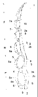
As shown in FIGS. 1 to 4, a sole assembly 1
according to an embodiment of the present invention is composed
of a heel portion H, a midfoot portion M, and a forefoot portion
F. The midfoot portion M is disposed in a region defined by
0.35L to 0.55L, measuring from a heel rear end edge of the
sole assembly 1 or a lower end edge of FIG.1, where L is the
entire length of the sole assembly 1. Also, a rear end of
the midfoot portion M or a boundary position relative to the
heel portion H, is disposed in a position defined by 0.35L
to 0.45L, measuring from the heel rear end edge of the sole
assembly 1. A front end of the midfoot portion M or a boundary
position relative to the forefoot portion F, is disposed in
a position defined by 0.45L to 0. 55L, measuring from the heel
CA 02661845 2011-06-07
- ''-
rear end edge of the sole assembly 1..
As shown in FIGS. 2 to 3, the sole assembly
1 includes an upper midsole 2 of a soft e Last i c member extend i op
from the heel portion H through the midfoot portion M to the
forefoot portion F, an upper plate 3 of a hard elastic member
attached on a bottom surface 2a of the upper midsole 2 and
extending from the heel portion H through the midfoot port ton
M to the forefoot portion F, a lower plate 4 of a hard c~latt= i c
member disposed below the upper plate 3, extending from th
heel portion H through the midfoot portion M to the forefoot
portion F, and having a downwardly convexedly curved shape
to form a void S with the upper plate 3, and outsoles 3, 6,
7 disposed on a bottom surface 4a of the lower plate 4.
The upper plate 3 has an upper surface 2b that
follows a contour of a sole of a shoe wearer's foot. A pa i-r
of upraised portions 2c are formed at laterally opposite side
edge portions of the upper surface 2b. The upraised lx rt. i or <;
2c are adapted to be fixedly attached to laterally t
sides of a bottom portion of an upper (not shown) of a shoe
when the upper is fitted to the upper midsole 2 during assembly
of the shoe. The bottom surface 2a of the upper midsole 2
is formed of a longitudinally advancing wavy surface with
laterally extending ridge lines at the heel portion H to the
forefoot portion F of the sole assembly 1. Preferably, the
bottom surface 2a of the upper midsole 2 at the midfoot port ion
CA 02661845 2009-02-25
- 12-
M is formed of an upwardly convexedly curved surface or a
longitudinally flat surface.
The upper midsole 2 is preferably formed of
a soft elastic member because it is disposed on the side close
S to the sole of the wearer's foot. For example, foamed
thermoplastic resin such as ethylene-vinyl acetate copolymer
(EVA) , foamed thermosetting resin such as polyurethane (PU)
and foamed rubber such as butadiene rubber or chloroprene
rubber may be used.
The upper plate 3 has a wavy surf ace that extends
from the heel portion H to the forefoot portion F of the sole
assembly 1 and that follows the contour of the wavy surface
of the bottom surface 2a of the upper midsole 2. A pair of
upraised wall portions 3a are formed at laterally opposite
side edge portions of the upper plate 3. The upraised wall
portions 3a are disposed outside the upraised portions 2c
of the upper midsole 2.
The upper plate 3 further has a laterally
advancing wavysurfacewiththelongitudinallyextending ridge
lines at the longitudinally central portion of the midfoot
portion M, as shown in FIG. 6. The bottom surface 2a of the
upper midsole 2 contacting the wavy surface of the upper plate
3 has a plurality of cushion holes 30.
The lower plate 4 has a wavy shape formed inverted
relative to the upper plate 3. That is, the lower plate 4
CA 02661845 2009-02-25
- 13-
has a downwardly convexedly curved shape at the position where
the lower plate 4 faces an upwardly convexedly curved shape
of the upper plate 3, and the lower plate 4 has an upwardly
convexedly curved shape at the position where the lower plate
4 faces a downwardly convexedly curved shape of the upper
plate 3. In addition, FIGS. 2 to 4 show the void S with no
fillers filled in, but a soft cushioning member such as sponge
may be filled in the void S.
The upper plate 3 and the lower plate 4 are
preferably formed of hard elastic plates in order to prevent
a loss in elasticity due to repetitive deformation to maintain
a shape of the void S between the upper and lower plates 3,
4 to some degree. For example, the upper and lower plates
3, 4maybeformedof thermoplastic resin such as thermoplastic
polyurethane (TPU) , polyamide elastomer (PAE) , ABS resin or
the like. Alternatively, the upper and lower plates 3, 4 may
be formed of thermosetting resin such as epoxy resin,
unsaturated polyester resin or the like. Also, the upper and
lower plates 3, 4 may be formed of fiber reinforced plastics
including carbon fibers, metal fibers or the like.
The hardness of the upper plate 3 is preferably
greater than the hardness of the lower plate 4. For example,
the hardness of the upper plate 3 is determined at a Shore
D hardness of 72 and the hardness of the lower plate 4 is
determined at a Shore D hardness of 55.
CA 02661845 2009-02-25
-14-
Of all the outsoles provided on the bottom
surface 4a of the lower plate 4, the outsole 5 is disposed
at the heel portion H of the sole assembly 1, the outsole
6 at the midfoot portion M, and the outsole 7 at the forefoot
portion F, respectively.
The outsoles 5, 7 at the heel portion H and
the forefoot portion F have ground contact surfaces 5a, 7a
to contact the ground and the outsole 6 at the midfoot portion
M also has a ground contact surface 6a as well to contact
the ground. As is clearly shown in FIG. 2, the ground contact
surface 6a of the outsole 6 is longitudinally separated from
the ground contact surfaces 5a, 7a of the outsoles 5, 7 at
the heel portion H and the forefoot portion F. In other words,
there is formed a clearance between the ground contact surface
6a of the outsole 6 and the ground contact surfaces 5a, -7a
of the outsoles 5, 7 that are longitudinally adjacent to the
outsole 6. As shown in FIGS. 1 and 3, the outsoles 5, 6, and
7 may be interconnected to each other at the base portions.
On the front and rear end sides of the midfoot
portionMof the sole assembly 1, there are provided connections
8 of an elastic member to interconnect the upper plate 3 with
the lower plate 4 in the vertical direction (see FIGS. 5 and
7) . Similarly, a connection 9 is provided at the heel portion
H and a connection 10 at the forefoot portion F. Each of the
connections 8, 9, 10 is preferably disposed at the position
CA 02661845 2009-02-25
- 15-
where the upper plate 3 and the lower plate 4 are vertically
closest to each other. That is, each of the connections 8,
9, 10 is provided at the position where the downwardly
convexedly curved portion of the upper plate 3 faces the
upwardly convexedly curved portion of the lower plate 4 in
the verticaldirection.Upper and lower ends of the connections
8, 9, 10 are fixedly attached to the upper and lower plates
3, 4, respectively. For example, each of the connections 8,
9, 10 is disposed at the laterally opposite end portions (and
the central portion) of the sole assembly 1.
In the example shown in FIG. 3, there are provided
a plurality of column-shaped reinforcement members 11 at the
positions where the upper and lower plates 3, 4 are located
farthest away from each other in the vertical direction on
the medial side of the sole assembly 1. These reinforcement
members 11 are provided in the light of preventing an excessive
downward sinking of themedial sideportionof the soleassembly
1 and securing the stability of the sole assembly 1 when a
load is applied to the medial side portion of the sole assembly
1. An upper end of each of the reinforcement members 11 is
fixed to the upper plate 3 but a lower end of each of the
reinforcement members 11 is not fixed to the lower plate 4
and has a gap (not shown) between the reinforcement member
11 and the lower plate 4. That is because when the load acts
on the sole assembly 1 the upper and lower plates 3, 4 are
CA 02661845 2009-02-25
-16-
allowed to deform to some degree without restricting a
deformation excessively and then by allowing the end of the
reinforcement member 11 to contact the lower plate 4 to prevent
an excessive downward sinking of the upper and lower plates
3, 4. In addition, when the cushioning properties are regarded
as an important factor in the sole assembly, then preferably
these reinforcement members 11 should be omitted.
In the above-mentioned sole assembly, since
the outsole 6 separated longitudinally from the outsoles 5,
7 of the heel portion H and the forefoot portion F is provided
at the midfoot portion M of the sole assembly, when the wearer
strikes onto the ground from the heel portion H of the sole
assembly and the load is transferred toward the forefoot
portion F the ground contact surface 6a of the outsole 6 at
the midfoot portion M comes into contact with the ground.
At this juncture, since the lower plate 4 disposed at the
lower position (i.e. the position close to the ground) in
the midfoot portion M has a downwardly convexedly curved shape
to form the void S with the upper plate 3, the lower plate
4 can deform upwardly thereby securing the cushioning
properties of the midfoot portion M. As a result, when the
load is transferred from the heel portion H through the midfoot
portion M to the forefoot portion F a smooth load transfer
is made possible and a ride feeling during running can be
improved.
CA 02661845 2009-02-25
-17-
Also, in this case, since the upper plate 3
disposed at the upper position (i.e. the position close to
the wearer's foot) in the midfoot portion M is formed of a
hard elastic member and also the upper plate 3 is coupled
to the lower plate 4 via the connections 8 on the front and
rear end sides of the midfoot portion M, at the time of applying
the load to the midfoot portion M deformation (i . e . bending
and torsional deformations) of the upper plate 3 can be more
securely prevented. Thereby, support rigidity relative to
an arch portion of the wearer's foot can be further improved
and the stability as the midfoot portion of the shoe can be
further enhanced.,
Moreover, in this case, since the upper plate
3 extends longitudinally in a generally flat shape or an
upwardly convexedly curved shape at the midfoot portion M,
at the time of applying the load to the midfoot portion M
a downward sinking of the upper plate 3 can be more effectively
prevented. Also, in this case, since the upper plate 3 can
be formed in a shape that follows a contour of the arch portion
of the foot of the wearer, fitting properties relative to
the arch portion can be enhanced.-
Furthermore, since the upper plate 3 has a
laterally advancing wavy shape with longitudinally extending
ridge lines, at the time of applying the load to the midfoot
portion M the crests and/or troughs of the wavyconfigurations
CA 02661845 2009-02-25
-1s-
of the upper plate 3 functions as ribs and the upper plate
3 is hard to bend in a V-shape. Thereby, a shank effect at
the midfoot portion M can be improved. Also, since the upper
midsole 2 is provided on the upper plate 3, a contact feeling
relative to the sole of the wearer's foot can be improved.
Moreover, when the hardness of the upper plate
3 is made greater than the hardness of the lower plate 4,
as the load acts on the midfoot portion M the lower plate
4 of a relatively low hardness easily deforms upwardly to
secure cushioning properties and the upper plate of a
relatively high hardness is hard to deform thus increasing
the support rigidity relative to the arch portion of the
wearer's foot.
In the above-mentioned embodiment, the example
was shown where the lower plate 4 is disposed opposite the
upper plate 3 and the outsoles 5, 6, 7 are provided on the
bottomsurface4aof the lowerplate 4 , but the present invention
is not limited to such an example.
FIG. 8 shows a side view of a sole assembly
according to another embodiment of the present invention.
In FIG. 8, like reference numbers indicate identical or
functionally similar elements. In a sole assembly 1' , a lower
midsole 15 of a soft elastic member is provided in lieu of
the lower plate 4 in the above-mentioned embodiment. The lower
midsole 15 extends from the heel portion H through the midfoot
CA 02661845 2011-06-07
-19-
portion M to the forefoot portion F under the upper plate
3 and has a downwardly convexedly curved upper surface 15a
to form a void S with the upper plate 3. The lower midsole
15 is in contact with the upper plate 3 on the front and rear
end sides of the midfoot portiori M. In this example, the dower
midsole15is in contact with the upper plate 3 at the heel
portion H and the forefoot portion F as well.
The upper surface 1.5a of the lower midsoic 1
has a wavy shape formed inverted relative to the upper plate
3. That is, the upper surface 15a of the lower midsole 15
has a downwardly convexedly curved surface at the position
opposite the position where the upper plate 3 has an upwardly
convexedly curved shape, and the upper surface 1.5a of the
lower midsole 15 has an upwardly convexedly curved surface
at the position opposite the position where the upper plate
3 has a downwardly convexedly curved shape.
The outsoles 5, 6, 7 are attached on the hot per:
surf acel5bofthel.owermidsole15.Aswiththeabove icre ~
embodiment, the outsole 5 is disposed at the bee' port :on
H of the sole assembly 1, the outsole 6 at the midfoot portion
M, and the outsole 7 at the forefoot portion F. The outsoles
5 of the heel portion I-1 and the outsoles 7 of the fore(=oot
portion F have ground contact surfaces 5a, 7a that contact
the ground. Similarly, the outsole 6 of the midfoot portion
M has a ground contact surface 6a as well that contacts the
CA 02661845 2009-02-25
-20-
ground. The outsole 6 is longitudinally separated from the
outsoles 5, 7 of the heel portion H and the forefoot portion
F. In other words, there is a gap formed between the outsole
6 and the longitudinally adjacent outsoles 5, 7.
In this case, because there is provided the
outsole 6 at the midfoot portion M of the sole assembly, which
is longitudinally separated from the outsoles 5, 7 at the
heel portion H and the forefoot portion F, when the wearer
impacts onto the ground from the heel portion H of the sole
assembly and the load travels toward the forefoot portion
F, the ground contact surface 6a of the outsole 6 comes into
contact with the ground. At this juncture, since the lower
midsole 15 disposed at the lower position (i . e . on the side
close to the ground) of the midfoot portion M has a downwardly
convexedly curved upper surface 15a to form the void S with
the upper plate 3, the lower midsole 15 can deform upwardly
thereby securing the cushioning properties of the midfoot
portion M. As a result of this, when the load is transferred
from the heel portion H through the midfoot portion M to the
forefootportionF, asmoothtraveloftheloadbecomespossible
and a ride feeling during running can be improved.
Moreover, in this case, since the upper plate
3 disposed at the upper position (i.e. on the side close to
the wearer's foot) of the midfoot portion M is formed of a
hard elastic member, deformation (i.e. bending and torsional
CA 02661845 2009-02-25
- 21-
deformations) of the upper plate 3 can be restrained at the
time of applying the load to the midfoot portion M. thereby,
the support rigidity relative to the arch portion of the
wearer's foot can be improved and the stability as the midfoot
portion of the shoe can be secured.
In addition, there may be provided a lower plate
of a hard elastic member on the upper surface 15a of the lower
midsole 15, which has a downwardly convexedly curved shape
to form a void S with the upper plate 3. In this case, the
bending rigidity as well as the torsional rigidity of the
entire midfoot portion can be enhanced.
INDUSTRIAL APPLICABILITY
As above-mentioned, the sole assembly according
to the present invention is useful for a sole structure for
a running shoe and the like.