Language selection

Search

Patent 2662455 Summary

Third-party information liability

Some of the information on this Web page has been provided by external sources. The Government of Canada is not responsible for the accuracy, reliability or currency of the information supplied by external sources. Users wishing to rely upon this information should consult directly with the source of the information. Content provided by external sources is not subject to official languages, privacy and accessibility requirements.

Claims and Abstract availability

Any discrepancies in the text and image of the Claims and Abstract are due to differing posting times. Text of the Claims and Abstract are posted:

  • At the time the application is open to public inspection;
  • At the time of issue of the patent (grant).
(12) Patent: (11) CA 2662455
(54) English Title: SUBSEA UMBILICAL
(54) French Title: OMBILICAL SOUS-MARIN
Status: Granted and Issued
Bibliographic Data
(51) International Patent Classification (IPC):
  • H01B 7/04 (2006.01)
(72) Inventors :
  • DEIGHTON, ALAN (United Kingdom)
  • WONG, JOE SIU KIT (United Kingdom)
(73) Owners :
  • TECHNIP FRANCE SA
(71) Applicants :
  • TECHNIP FRANCE SA (France)
(74) Agent: NORTON ROSE FULBRIGHT CANADA LLP/S.E.N.C.R.L., S.R.L.
(74) Associate agent:
(45) Issued: 2015-07-21
(86) PCT Filing Date: 2007-09-04
(87) Open to Public Inspection: 2008-03-20
Examination requested: 2012-08-14
Availability of licence: N/A
Dedicated to the Public: N/A
(25) Language of filing: English

Patent Cooperation Treaty (PCT): Yes
(86) PCT Filing Number: PCT/GB2007/003307
(87) International Publication Number: WO 2008032019
(85) National Entry: 2009-03-02

(30) Application Priority Data:
Application No. Country/Territory Date
0618108.5 (United Kingdom) 2006-09-14
0711859.9 (United Kingdom) 2007-06-20

Abstracts

English Abstract

An umbilical for use in the offshore production of hydrocarbons, the umbilical comprising a plurality of functional elements contained within an outer sheath, at least one of said functional elements comprising a multicore electric cable, said multicore electric cable comprising a plurality of insulated electric conductors electrically insulated from each other and assembled together in a helical or S/Z manner, said multicore electric cable further comprising a protective polymer sheath surrounding said plurality of insulated electric conductors, said multicore electric cable further comprising a tubular metallic layer located inside said protective polymer sheath and surrounding said plurality of insulated electric conductors.


French Abstract

La présente invention concerne un ombilical conçu pour être utilisé dans la production offshore d'hydrocarbures. Cet ombilical comprend plusieurs éléments fonctionnels contenus dans une gaine externe, au moins un de ces éléments fonctionnels comprenant un câble électrique multiconducteur qui comporte plusieurs conducteurs électriques isolés, lesquels conducteurs sont isolés les uns des autres et sont assemblés selon une configuration hélicoïdale ou S/Z, ainsi qu'une gaine protectrice en polymère qui entoure lesdits conducteurs électriques isolés et une couche métallique tubulaire qui se trouve à l'intérieur de la gaine protectrice en polymère et qui entoure lesdits conducteurs électriques isolés.

Claims

Note: Claims are shown in the official language in which they were submitted.

8
Claims
1. An umbilical for use in the offshore production of hydrocarbons, the
umbilical
comprising a plurality of functional elements contained within an outer
sheath, at least one of
said functional elements comprising a multicore electric cable, said multicore
electric cable
comprising a plurality of insulated electric conductors electrically insulated
from each other
and assembled together in a helical or S/Z manner, said multicore electric
cable further
comprising a protective polymer sheath surrounding said plurality of insulated
electric
conductors, said multicore electric cable further comprising a tubular
metallic layer located
inside said protective polymer sheath and surrounding said plurality of
insulated electric
conductors.
2. An umbilical as claimed in claim 1, wherein the multicore electric cable
comprises a
low voltage multicore electric cable.
3. An umbilical as claimed in claim 1 or claim 2, wherein the tubular
metallic layer is
made of copper.
4. An umbilical as claimed in claim 1 or claim 2, wherein the tubular
metallic layer is
made of aluminium.
5. An umbilical as claimed in any one of claims 1 to 4, wherein the tubular
metallic layer
is made of a metal strip helically wrapped with overlap around the plurality
of insulated electric
conductors.
6. An umbilical as claimed in any one of claims 1 to 4, wherein the tubular
metallic layer
is made of a metal strip longitudinally folded with overlap around the
plurality of insulated
electric conductors.
7. An umbilical as claimed in claim 5 or claim 6, wherein the metal strip
is bonded at the
overlap.
8. An umbilical as claimed in claim 5 or claim 6, wherein the metal strip
is welded at the
overlap.
9. An umbilical as claimed in any one of claims 5 to 8, wherein the
protective polymer
sheath is bonded to the tubular metallic layer.

9
10. An umbilical as claimed in any one of claims 1 to 9, wherein a hydrogen
absorbent
material is provided inside at least one of the insulated electric conductors.
11. An umbilical as claimed in any one of claims 1 to 10, wherein a
hydrogen absorbent
material is provided inside the interstitial voids between the plurality of
insulated electric
conductors and the tubular metallic layer.

Description

Note: Descriptions are shown in the official language in which they were submitted.


CA 02662455 2009-03-02
WO 2008/032019 PCT/GB2007/003307
1
SUBSEA UMBILICAL
The present invention relates to an umbilical for use in the offshore
production of hydrocarbons.
In subsea oil field operations, umbilicals are used to transport fluids,
power, signals or data to and from a subsea installation. An umbilical
comprises a group of one or more types of functional elements such as
multicore low voltage electric cables, optical fibre cables, or hoses for
fluid
transportation of, for example, gas, water or chemical products such as
methanol. These functional elements are assembled together in a helical
or S/Z manner and over-sheathed and/or over-armoured for mechanical
strength and ballast. It is desirable for a single umbilical to be able to
contain as many functional elements as are required for a particular
application, for example, as are required for a particular oil field where the
umbilical is intended for use.
In the present application, "low voltage" should be understood as rated for
a voltage smaller than 3000V, and typically smaller than 1000V. Low
voltage multicore cables of subsea umbilicals are generally used to carry
single phase power for control purposes and signal transmission. Typically
a low voltage multicore power cable used in a subsea umbilical is rated at
250V and 3A, so around 750W in power. Low voltage multicore signal
cables used in subsea umbilicals are operated at frequencies up to 20
kHz. These multicore low voltage cables typically have a very simple
construction. Indeed, because of their low voltage, such multicore cables
are not sensitive to moisture ingress, unlike medium and high voltage
coaxial power cables (respectively rated at 6kV to 30kV and at more than
30kV) which are known to be very sensitive to water ingress and may

CA 02662455 2009-03-02
WO 2008/032019 PCT/GB2007/003307
2
develop detrimental defects known as "water tree", and therefore require
additional protective sheaths to prevent moisture ingress.
A problem with known electric cables within subsea umbilicals is that, over
an extended period of time, in some circumstances related to the
presence of sea water, small quantities of hydrogen appear inside the
umbilical structure, and then diffuse inside the electric cables. The
presence and the circulation of hydrogen gas inside the electric cables
have several detrimental effects.
The object of the present invention is to minimise or overcome this
disadvantage.
According to the invention, there is provided an umbilical for use in the
offshore production of hydrocarbons, the umbilical comprising a plurality of
functional elements contained within an outer sheath, at least one of said
functional elements comprising a multicore electric cable, said multicore
electric cable comprising a plurality of insulated electric conductors
electrically insulated from each other and assembled together in a helical
or S/Z manner, said multicore electric cable further comprising a protective
polymer sheath surrounding said plurality of insulated electric conductors,
said multicore electric cable further comprising a tubular metallic layer
located inside said protective polymer sheath and surrounding said
plurality of insulated electric conductors.
The metallic layer acts as a barrier against the diffusion of hydrogen from
the outside to the inside of the cable. This solution greatly reduces the
amount of hydrogen gas diffusing inside the electric cable and inside the
different electric conductors thereof, thus greatly reducing the amount of
hydrogen gas circulating along the electric cable and conductors.

CA 02662455 2009-03-02
WO 2008/032019 PCT/GB2007/003307
3
Preferably the multicore electric cable comprises a low voltage multicore
electric cable.
Preferably, the tubular metallic layer is made of copper or aluminium.
Copper is preferred because it has a lower permeability to hydrogen than
aluminium.
According to a preferred embodiment of the invention, the tubular metallic
layer is made of a metal strip helically wrapped with overlap around the
plurality of insulated electric conductors.
According to another preferred embodiment of the invention, the tubular
metallic layer is made of a metal strip longitudinally folded with overlap
around the plurality of insulated electric conductors.
Preferably, the metal strip is also bonded or welded at the overlap, in order
to improve its hydrogen gas tightness.
More preferably, the protective polymer sheath is also bonded to the
tubular metallic layer. This prevents hydrogen gas from circulating along
the cable between the tubular metallic layer and the protective polymer
sheath.
Preferably, a hydrogen absorbent material is also provided inside at least
one of the insulated electric conductors, so as to maintain the electric
conductor in a substantially hydrogen free environment. Therefore, the
small amount of hydrogen which has not been stopped by the tubular
metallic layer is immediately suppressed by its chemical reaction with the
hydrogen absorbent material contained inside the electric conductor.

CA 02662455 2009-03-02
WO 2008/032019 PCT/GB2007/003307
4
Preferably, a hydrogen absorbent material is also provided inside the
interstitial voids between the plurality of insulated electric conductors and
the tubular metallic layer, and/or any filler material. This characteristic
has
a similar technical effect as the previous one.
Preferred embodiments of the present invention will now be described, by
way of example, with reference to the accompanying drawings, in which:-
Figure 1 is a cross section of a subsea umbilical according to an
embodiment of the present invention;
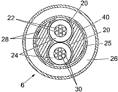
Figure 2 is a cross section of a low voltage multicore electric cable for use
in an umbilical according to a first embodiment of the present invention;
Figure 3 is a cross section of a low voltage multicore electric cable for use
in an umbilical according to a second embodiment of the present
invention.
As illustrated in Figure 1, a subsea umbilical 1 contains a plurality of
functional elements, including several hoses 2,3,4,5 and four multicore low
voltage electric cables 6,7,8,9 (although other numbers of cables and
functional elements are envisaged). These functional elements are
assembled in S/Z manner together with fillers 10 and over-sheathed 11
and armoured 12 to form the umbilical.
In a first embodiment of the present invention, as illustrated in Figure 2,
each multicore low voltage electric cable 6 comprises two electric
conductors 20. However, it is envisaged that the multicore low voltage
electric cable may comprise more than two conductors 20, typically three

CA 02662455 2009-03-02
WO 2008/032019 PCT/GB2007/003307
or four conductors. In the example shown, each conductor is made of
seven stranded circular copper wires 22. It could also be possible to used
solid conductors (according to the IEC 60228 International Standard)
without departing from the present invention. Each conductor 20 is
5 sheathed by an electrical insulation polymer sheath 24. Both insulated
conductors 20 are assembled in a helical or S/Z manner together with filler
material 25 to form a substantially cylindrical core. A copper tubular layer
40 surrounds this cylindrical core and thus both insulated conductors. The
copper tubular layer 40 acts as a barrier reducing the hydrogen diffusion
from the outside to the inside of the multicore low voltage electric cable 20.
As well as protecting the cable from hydrogen ingress, the copper tubular
layer 40 can also provide a further function, such as providing electrical
grounding or shielding. The copper tubular layer 40 is over sheathed by a
protective polymer sheath 26.
The copper tubular layer 40 may be made from a copper tape applied
longitudinally and folded around the cylindrical core just before the
extrusion of the protective polymer sheath 26. The copper tape has a
typical thickness of 100 micrometers and is coated with a 25 micrometers
thick copolymer which melts during the extrusion of the protective polymer
sheath 26. This copolymers bonds to the protective polymer sheath 26
and also bonds to the overlapping copper, thus ensuring in a single step
both the tightness of the tubular layer 40 at the overlap of the copper tape
and the bonding of the tubular layer 40 with the protective polymer sheath
26.
The copper tubular layer 40 may alternatively be formed from a copper
tape applied helically around the cylindrical core with continuous bonding
at the overlap in order to achieve good hydrogen gas tightness. This
solution improves the fatigue resistance of the cable under dynamic

CA 02662455 2009-03-02
WO 2008/032019 PCT/GB2007/003307
6
bending stresses. Preferably, glue is applied on the outside surface of the
copper tubular layer 40 before the extrusion of the protective polymer
sheath 26, thus bonding the copper tubular layer 40 with the protective
polymer sheath 26.
Preferably, the interstices 30 between the copper wires 22 of conductors
20 are filled with a hydrogen absorbent material. Optionally, the interstices
28 between the insulated conductors 20 and the filler material 25, and
between the filler material 25 and the copper tubular layer 40, are also
filled with a hydrogen absorbent material. The hydrogen absorbent
material may also be provided within the filler material 25. Thus, the
residual hydrogen that is not stopped by the copper tubular layer 40 is
suppressed by its reaction with the hydrogen absorbent material.
Suitable hydrogen absorbent materials comprise, for example, gels
comprising sodium aluminium silicates which are rendered hydrogen
absorbent by replacement of at least some of the sodium by an active
metal, typically silver. Such materials are commonly known as zeolite.
Figure 3 shows an electric cable for use in an umbilical according to a
second embodiment of the present invention. It differs from the previous
embodiment by the fact that it comprises armouring wires 50 within the
protective polymer sheath 26 for improving the mechanical resistance of
the cable 20
Various modifications and variations to the described embodiments of the
inventions will be apparent to those skilled in the art without departing from
the scope of the invention as defined in the appended claims. Although
the invention has been described in connection with specific preferred

CA 02662455 2009-03-02
WO 2008/032019 PCT/GB2007/003307
7
embodiments, it should be understood that the invention as claimed
should not be unduly limited to such specific embodiments.

Representative Drawing
A single figure which represents the drawing illustrating the invention.
Administrative Status

2024-08-01:As part of the Next Generation Patents (NGP) transition, the Canadian Patents Database (CPD) now contains a more detailed Event History, which replicates the Event Log of our new back-office solution.

Please note that "Inactive:" events refers to events no longer in use in our new back-office solution.

For a clearer understanding of the status of the application/patent presented on this page, the site Disclaimer , as well as the definitions for Patent , Event History , Maintenance Fee  and Payment History  should be consulted.

Event History

Description Date
Maintenance Fee Payment Determined Compliant 2024-08-26
Maintenance Request Received 2024-08-26
Common Representative Appointed 2019-10-30
Grant by Issuance 2015-07-21
Inactive: Cover page published 2015-07-20
Inactive: Final fee received 2015-04-28
Pre-grant 2015-04-28
Notice of Allowance is Issued 2014-10-29
Letter Sent 2014-10-29
Inactive: Approved for allowance (AFA) 2014-10-21
Inactive: Q2 passed 2014-10-21
Letter Sent 2014-10-03
Amendment Received - Voluntary Amendment 2014-10-02
Maintenance Request Received 2014-09-23
Reinstatement Request Received 2014-09-23
Reinstatement Requirements Deemed Compliant for All Abandonment Reasons 2014-09-23
Deemed Abandoned - Failure to Respond to Maintenance Fee Notice 2014-09-04
Inactive: S.30(2) Rules - Examiner requisition 2014-04-07
Inactive: Report - No QC 2014-03-26
Inactive: Office letter 2013-09-30
Inactive: Correspondence - Prosecution 2013-08-08
Letter Sent 2012-09-04
Request for Examination Received 2012-08-14
All Requirements for Examination Determined Compliant 2012-08-14
Request for Examination Requirements Determined Compliant 2012-08-14
Inactive: Cover page published 2009-07-03
Inactive: Notice - National entry - No RFE 2009-06-08
Inactive: First IPC assigned 2009-05-09
Application Received - PCT 2009-05-08
National Entry Requirements Determined Compliant 2009-03-02
Application Published (Open to Public Inspection) 2008-03-20

Abandonment History

Abandonment Date Reason Reinstatement Date
2014-09-23
2014-09-04

Maintenance Fee

The last payment was received on 2014-09-23

Note : If the full payment has not been received on or before the date indicated, a further fee may be required which may be one of the following

  • the reinstatement fee;
  • the late payment fee; or
  • additional fee to reverse deemed expiry.

Please refer to the CIPO Patent Fees web page to see all current fee amounts.

Owners on Record

Note: Records showing the ownership history in alphabetical order.

Current Owners on Record
TECHNIP FRANCE SA
Past Owners on Record
ALAN DEIGHTON
JOE SIU KIT WONG
Past Owners that do not appear in the "Owners on Record" listing will appear in other documentation within the application.
Documents

To view selected files, please enter reCAPTCHA code :


To view images, click a link in the Document Description column. To download the documents, select one or more checkboxes in the first column and then click the "Download Selected in PDF format (Zip Archive)" or the "Download Selected as Single PDF" button.

List of published and non-published patent-specific documents on the CPD .

If you have any difficulty accessing content, you can call the Client Service Centre at 1-866-997-1936 or send them an e-mail at CIPO Client Service Centre.


Document
Description 
Date
(yyyy-mm-dd) 
Number of pages   Size of Image (KB) 
Description 2009-03-02 7 272
Drawings 2009-03-02 2 81
Abstract 2009-03-02 2 73
Claims 2009-03-02 2 61
Representative drawing 2009-06-09 1 17
Cover Page 2009-07-03 1 49
Claims 2014-10-02 2 43
Cover Page 2015-07-07 1 50
Confirmation of electronic submission 2024-08-26 2 69
Reminder of maintenance fee due 2009-06-08 1 110
Notice of National Entry 2009-06-08 1 192
Reminder - Request for Examination 2012-05-07 1 118
Acknowledgement of Request for Examination 2012-09-04 1 177
Courtesy - Abandonment Letter (Maintenance Fee) 2014-10-03 1 174
Notice of Reinstatement 2014-10-03 1 164
Commissioner's Notice - Application Found Allowable 2014-10-29 1 162
PCT 2009-03-02 2 62
Correspondence 2013-09-30 1 20
Fees 2014-09-23 2 68
Correspondence 2015-04-28 2 65