Note: Descriptions are shown in the official language in which they were submitted.
CA 02662522 2009-02-27
WO 2008/028169
PCT/US2007/077465
1
DIRECT LIQUID-PHASE COLLECTION AND PROCESSING OF FULLERENIC
MATERIALS
GENERAL AREA OF TECHNOLOGY
[0001] The invention relates generally to an in-situ method of
collecting fullerenic
material, such as fullerenes and nanotubes, in a non-agglomerated state.
BACKGROUND
[0002] Fullerenic materials may be synthesized using a laser to
ablate graphite,
burning graphite in a furnace or by producing an arc across two graphite
electrodes in an inert
atmosphere. Combustion of a fullerenic-forming fuel under well-controlled
conditions has
evolved to be an attractive method particularly for high volume production. In
each method,
condensable matter comprising a mixture of soot, other insoluble condensed
matter, C60, C705
and higher as well as lower numbered fullerenes, and polycyclic aromatic
hydrocarbons
(PAH) in varying amounts is collected as a condensed solid, with the total
fullerene fraction
typically between 5 and 15% of the total material collected, and soot being
80% - 95% of the
remaining total material. Carbon nanotubes, also part of the class of
fullerenic materials, can
be synthesized in significant yields with the use of metal catalysts in
electric arc, combustion,
laser ablation or chemical vapor deposition systems. The relative abundance of
multi-walled
(MWCNT) or single-walled carbon nanotubes (SWCNT) depends strongly on the
catalyst
added. For instance, the addition of iron pentacarbonyl as a catalyst
precursor to premixed
hydrocarbon/oxygen allows for the selective formation of SWCNT. Between 25% to
greater
than 40% by weight of SWCNT in condensed material can be typically obtained,
with the
remainder the material being mainly iron and iron oxide.
[0003] Forming dispersions of fullerenic materials from condensed
solids gathered by
these synthetic routes can be difficult. Although techniques such as
exfoliation, dispersion
and debundling of nanotubes in solution have been reported, these techniques
require
selecting a specific surfactant and solvent to enhance the dispersion, in
addition to applying
some method of physical agitation, such as ultrasonification or
centrifugation. Dispersions
formed by this process, however, tend to readily agglomerate and in many
cases, do not
sufficiently disperse. Moreover, significant quantities of surfactant is
generally required for
the dispersion, which is not always compatible with later processing steps
that may be
required to utilize the fullerenic material. The presence of surfactants can
also reduce the
CA 02662522 2009-02-27
WO 2008/028169
PCT/US2007/077465
2
effectiveness or functionality of the fullerenic material. For instance, the
enhancement of
electric conductivity by nanotubes drops sharply when the necessary quantity
of surfactant to
disperse the nanotubes is present. In addition, sonication may induce defects
in the SWCNT
and introduce unwanted properties in the SWCNT. Thus, the formation of stable
solutions
having significant amounts of non-agglomerated nanotubes remains elusive.
[0004] The capture of aerosol combustion products, such as amorphous
carbonaceous
particles, has been performed to help assess their potential health hazardous
effect, as well as
to study the size distribution of particles at different locations within and
above a combustion
flame. An aerosol is composed of solid (or liquid) particles in a gas
suspension. For
purposes of studying particle size, the most important consideration is to
avoid altering the
particle mass concentration, number concentration, and size distributions by
the measuring
equipment so that the collected sample at the sampling position has same
properties as
particles made by an undisturbed flame. Particles made by combustion processes
are affected
by size-dependent forces such as gravity, diffusion and inertia. For small
particles, e.g., less
than about 500 nm, diffusion is by far the most important size-dependent
force. Diffusion is
the net transport of particles from a region of higher concentration to a
region of lower
concentration caused by the particles' Brownian motion. The relative motion
between
particles that is caused by diffusion is termed thermal coagulation. Depending
on the
strength of the intermolecular interactions between particles, thermal
coagulation can lead to
agglomeration of particles, e.g., clusters of particles. Whether particles
will agglomerate
depends strongly on collision efficiencies between the particles involved.
Because of strong
Van der Waals forces between fullerenic materials, particularly nanotubes,
thermal
coagulation can pose a major challenge for sampling combustion product that is
unaffected
by agglomeration.
SUMMARY
[0005] Liquid and gas-phase collection of fullerenic carbon material
is described,
which may be appropriate for production processes that produce fullerenic
material as a gas,
a condensable solid or as a solid suspended in a gaseous phase. The fullerenic
materials are
entrained, as gases or solids, in an entrainment medium such as an entrainment
gas, vapor, or
gas-borne liquid droplets. The fullerenic materials are transferred from the
entrainment
medium to a suspension liquid in a diluted state and are maintained in the
suspension liquid
in a non-agglomerated state. Methods to quench or minimize the extent of
chemical reactions
CA 02662522 2009-02-27
WO 2008/028169
PCT/US2007/077465
3
and physical processes such as agglomeration and to facilitate liquid-phase
product
processing are also provided.
[0006] In some aspects, the method and system entrains gas borne
particles of
fullerenic material in an entrainment medium, such as a vapor stream or
condensable gas.
The vapor stream or condensable gas may be in a vapor or gaseous state, which
is capable of
condensing or forming a liquid phase.
[0007] In one aspect, the method collects non-agglomerated fullerenic
material in a
process that includes creating a stream of entrainment medium, contacting the
stream of
entrainment medium to fullerenic material that is a gas or a solid in a
gaseous suspension so
as to entrain the fullerenic material in the stream, collecting the stream
containing fullerenic
material, and condensing the stream containing fullerenic material into a
liquid suspension.
[0008] In one or more embodiments, the fullerenic material is
generated in situ at a
synthesis site, and the fullerenic materials are entrained in the entrainment
medium in-situ.
By in-situ, it is meant that the fullerenic material is not collected as a
powder or other solid
prior to the liquid-phase collection process described herein. In other
embodiments, the
fullerenic materials are re-suspended as a particulate aerosol prior to
entrainment by the
entrainment medium. The entrainment medium containing the fullerenic material
is
condensed from a vapor or gas to a liquid and at least a portion of the
fullerenic material is
incorporated into the condensed liquid. Because the fullerenic material is
collected in a
liquid or gas in a highly dilute state, it is initially in a non-agglomerated
state. With
appropriate control of the nature of the solvent and the concentration of
fullerenic material in
the resultant liquid suspension, and the optional inclusion of surfactants,
the fullerenic
material can be maintained in a non-agglomerated state.
[0009] In some embodiments, the liquid forms finely dispersed liquid
droplets, such
as a liquid droplet aerosol. The liquid droplets are subsequently delivered to
a collection
zone, where the fullerenic material is collected and maintained in a liquid
suspension. In
another aspect, the method and system collects fullerenic material, such as
nanotubes, in
liquid suspension from a gaseous suspension of nanotubes. The gas comprising
the
suspension may originate from the combustion products generated during the
combustion
synthesis of the nanotubes. A carrier gas may be optionally introduced to the
suspended
nanotube particles after the production of the fullerenic product. The gaseous
suspension
containing the nanotubes is then contacted with a liquid that can capture the
nanotubes and
provide a nanotube liquid suspension in which the nanotubes are in a
substantially non-
agglomerated state. Depending on the chosen solvent, concentrations of up to
about 25 to 30
CA 02662522 2009-02-27
WO 2008/028169
PCT/US2007/077465
4
mg/mL of fullerenes and up to 5 mg/mL of nanotubes can be obtained and
maintained in a
non-agglomerated states. In some embodiments, an operator may increase the
concentration
of fullerenic material in the suspension liquid by recycling the collected
liquid suspension to
entrain additional fullerenic material.
[0010] In one embodiment, a method of collecting non-agglomerated
fullerenic
material is provided, comprising: contacting a gaseous suspension comprising
fullerenic
material with a suspension liquid, wherein the suspension liquid captures the
fullerenic
material; and collecting a liquid suspension comprising the suspension liquid
containing the
captured fullerenic material. In a further embodiment, the fullerenic material
used in the
method described herein is a condensable gas, a condensed solid, and/or solid
particulate. In
one or more preferred embodiments, the fullerenic material comprises
fullerenes and/or
nanotubes. The methods described herein may be applied to fullerenic material
produced in a
flame combustion process in the presence of a catalyst. In one or more
embodiments, the
fullerenic materials may be made by combusting an unsaturated hydrocarbon fuel
and oxygen
in a burner chamber at sub-atmospheric pressures.
[0011] In an alternative embodiment, the gaseous suspension of
fullerenic material
comprises a diluent gas. The diluent may be an inert gas, a reactive gas, gas
vapor, nitrogen,
a noble gas, carbon dioxide, steam, flue gases, or mixtures thereof.
[0012] In one or more embodiments, the suspension liquid comprises an
organic
solvent or an aqueous solution. The suspension liquid may optionally include
one or more
additives, such as oxidation agents, acids, bases, surfactants, radical
scavengers, chemical
quenching agents, and chemical stabilization agents. The organic solvent, in
one or more
embodiments, may be, for instance, substituted aromatic molecules, alkyl
substituted
aromatics, halogenated substituted molecules, halogenated alkanes, partially
hydrogenated
aromatics, alkylamines, cyclic ethers, ortho-dichlorobenzene, xylene, benzene,
dimethylformamide, ethylene chloride, chloroform, 1,2,4 trimethylbenzene,
1,2,3,4
tetramethylbenzene, tetrahydrofuran, 1,2 dibromobenzene, 1,1,2,2,
tetrachloroethane, 1,2,3,4
tetrahydronapthalene, octadecylamine, acetone, and mixtures thereof. The
aqueous solution,
in one or more embodiments, comprises surfactant, such as sodium cholate,
NaDDBS
(Ci2H25C6H4S03Na), sodium octylbenzene sulfonate (Na0BS; C8H17C6H4S03Na),
sodium
butylbenzene sulfonate (NaBBS; C4H9C6H4S03Na), sodium benzoate (C6H5CO2Na),
sodium
dodecyl sulfate (SDS; CH3(CH2)11-0S03Na) (TX100; C8Hi7C6H4(OCH2CH2)n-OH; n ¨
10),
dodecyltrimethylammonium bromide (DTAB; CH3(CH2)11N(CH3)3Br), dextrin, and
poly(styrene)-poly-(ethylene oxide) (PS-PEO) diblock copolymer. The method
described
CA 02662522 2009-02-27
WO 2008/028169
PCT/US2007/077465
may further include liquid-phase processing of the fullerenic material, such
as, extracting a
class of fullerenic material from the suspension, acid extraction of catalyst
particles,
oxidation treatment of catalyst particles, oxidative opening of fullerenic
materials; shortening
nanotubes, exfoliating and dispersing nanotube bundles, ropes and rafts,
dispersing
5 -- nanotubes, and derivatizing the fullerenic material.
[0013] In one or more alternative embodiments, the gaseous suspension
is contacted
with the suspension liquid by creating a stream of the suspension liquid, said
stream
comprising a gas, vapor, or liquid droplets of the suspension liquid;
contacting the stream of
the suspension liquid with the gaseous suspension of fullerenic material in an
entrainment
-- zone so as to entrain the fullerenic material in the stream of suspension
liquid; and collecting
the contacted liquid suspension by condensing to a bulk liquid the stream of
suspension
liquid. In a further alternative embodiment, the gaseous suspension is
contacted with the
suspension liquid in an entrainment zone having a temperature, wherein the
temperature of
the entrainment zone is controlled. In one or more embodiments, the
temperature is
-- controlled to be at a selected temperature to prevent the suspension liquid
from condensing in
the entrainment zone. In an alternative embodiment, contacting the stream of
suspension
liquid with the gaseous suspension of fullerenic material further comprises
injecting the
stream of suspension liquid to intersect with the gaseous suspension of
fullerenic material. In
one or more embodiments, the stream of suspension liquid comprises the bulk
liquid. In a
-- further alternative embodiment, a portion of the bulk liquid is directed
for use in providing a
subsequent stream of suspension liquid.
[0014] In one or more alternative embodiments, contacting the gaseous
suspension of
fullerenic material with the suspension liquid comprises bubbling the gaseous
suspension
through the suspension liquid.
[0015] In addition, a collection system for collecting non-agglomerated
fullerenic
material is described herein, comprising: a first chamber, said chamber
comprising a first
inlet to receive a gaseous suspension comprising fullerenic material, a second
inlet to deliver
a suspension liquid into the first chamber and an outlet; an injection
apparatus coupled to said
second inlet, said injection apparatus is configured and arranged to generate
a gas, liquid
-- vapor, or liquid droplets of a suspension liquid, and a liquid collector
that is in flow
communication with the first chamber through said outlet, said collector
comprising a
condenser capable of condensing the gas, liquid vapor or liquid droplets of
suspension liquid,
and a reservoir for receiving a condensed suspension liquid.
CA 02662522 2009-02-27
WO 2008/028169
PCT/US2007/077465
6
[0016] In or more embodiments, the first inlet on the collection
system is in flow
communication with a combustion reactor that is configured and arranged to
produce a
gaseous suspension of a fullerenic material. In a further alternative
embodiment, the system
comprises a third inlet that is in flow communication with the first chamber
to accept and mix
a diluent gas with the fullerenic material. In one or more embodiments, the
injection
apparatus is, for example, an eductor, porous plate, nebulizer,
electrosprayer, or sonicator.
The system described herein may further comprise a heater which is in thermal
contact with
the first chamber, and which has a temperature that can be controlled. In one
or more
embodiments, the heater is capable of generating a temperature gradient in the
first chamber.
[0017] In one or more alternative embodiments, the condenser in the
collection
system is a liquid disengagement column, wherein the reservoir is located
below the liquid
disengagement column. The collection system may optionally include in the
liquid
disengagement column a separation medium, to facilitate separating the
fullerenic material
from the gaseous suspension In one or more embodiments, the separation medium
may be,
for example, glass beads, shell-shaped articles, irregular shaped articles, or
sand.
[0018] In one or more alternative embodiments, the collection system
further
comprises a recycle conduit in flow communication with the reservoir and the
injection
apparatus so as to direct the condensed suspension liquid to the injection
apparatus. The
collection system may further include a dispersement device to disperse a
portion of the
liquid suspension at the top of the condenser. In a further alternative
embodiment, a portion
of the condensed suspension liquid in the recycle conduit is directed to the
dispersement
device.
[0019] These and other features will be apparent upon consideration
of the following
detailed description of preferred embodiments thereof, presented in connection
with the
following drawings in which like reference numerals identify like elements
throughout. The
invention is not limited to achieve the objects and advantages described
herein, and may
achieve other objects and advantages. In addition, the non-limiting
embodiments of the
invention may not achieve any of the stated objects or advantages herein.
CA 02662522 2009-02-27
WO 2008/028169
PCT/US2007/077465
7
DESCRIPTION OF THE DRAWINGS
[0020] A more complete appreciation of the invention and many of its
advantages
will be understood by reference to the description of the invention when
considered in
connection with the following drawings, which are presented for the purpose of
illustration
only and are not intended to be limiting and in which:
[0021] Figure 1 is a schematic illustration of liquid collection of
fullerenic material in
a suspension liquid according to one or more embodiments.
[0022] Figure 2 is a schematic illustration of a direct-liquid
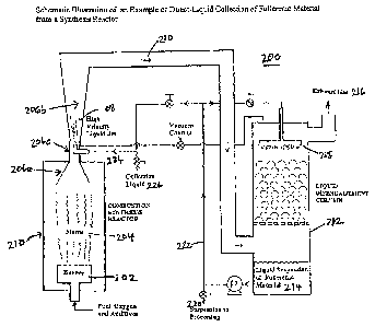
collection of fullerenic
material from a synthesis reactor.
DETAILED DESCRIPTION
[0023] The term "fullerenic material," as used herein, may include
fullerenes,
fullerenic black or soot, and fullerenic nanostructures of various shapes
including onions,
single-walled and multi-walled carbon nanotubes. The composition of the
material is usually
primarily carbon but other elements may be present. The nanostructures may
consist of one
or more concentric or approximately concentric walls. The different types of
fullerenic
material may be at different stages of growth and exhibit different degrees of
agglomeration,
and may occur with amorphous or other forms of carbon. When catalysts are
used, for
example as floating or entrained particles, the catalyst particles may be at
different stages of
growth and agglomeration. The methods described herein may be applied to
combustion,
chemical vapor deposition, or any other type of process that produces
fullerenic material in
the vapor phase, as particles suspended in a gas phase, or in any other state
in which the
material is amenable to entrainment by an entrainment medium or capture by a
suspension
liquid.
[0024] The term "entrainment medium" may be a liquid, vapor, or gas,
or any
combination thereof, which is capable of being condensed to a liquid.
[0025] "Fullerenes" is defined to include cagelike, hollow molecules
composed of
hexagonal and pentagonal groups of atoms, preferably carbon atoms.
[0026] "Nanotubes" is defined as an elongated cage or cylinder of
atoms such as
carbon. The nanotubes may comprise one or more concentric cylinders of carbon
atoms.
[0027] "Gaseous suspension" is defined to include gas molecules, liquid or
solid,
which is suspended in a gaseous medium.
CA 02662522 2015-01-21
8
[0028] In one or more embodiments, the fullerenic material is
generated from a
combustion reaction according to methods known in the art. Combustion
synthesis of
fullerenes and/or nanotubes have been described in U.S. Patent Nos. 5,273,729;
5,985,232,
and 6,162,411.
Figure 2 shows a
combustion chamber using a laminar flow system, which is an appropriate system
for small
scale set production. Larger scale production may benefit from the use of a
reactor that
invokes turbulent flow. Such a reactor is described in U.S. Patent Publication
No.
US 2005-0147552, published on July 7, 2005. The
same principles and methods
used to collect fullerenic material on a small-scale from a combustion chamber
may be
applied to a larger scale reactor.
[0029] The principles of fullerenic material production, aerosol
formation and liquid
collection are described herein with reference to the combustion synthesis of
fullerenic
materials. It is recognized, however, that fullerenic materials made by other
well-known
methods, e.g., electric arc, laser ablation and chemical vapor deposition,
that also result in
fullerenic products that can be generated as a gaseous suspension which are
suitable for use
in the methods disclosed herein.
[0030] In a combustion synthesis reaction, a fullerenic nanostructure
is prepared by
establishing a flame by combustion of an unsaturated hydrocarbon fuel and
oxygen in a
burner chamber at sub-atmospheric pressures. The fuel may be combusted in a
laminar flame
or in a turbulent flame. The combustion process may use a premixed or
diffusion flame. The
combustion process may use a one-dimensional flame. Exemplary combustion
conditions
include a burner chamber at pressures in the range of 20 to 300 ton, and more
preferably 80
to 200 torr; the diluent concentration is in the range of 0-50 vol %; the
carbon to oxygen ratio
(C/0) is in the range of 0.85 to 1.10; and the gas velocity is in the range of
25 to 50 cm/sec.
Preferred diluents include argon, nitrogen, carbon dioxide, steam, flue gases
and mixtures
thereof. If it is desired to prepare carbon nanotubes, a catalyst is
introduced into the flame to
promote the formation of single shell fullerenic nanotubes. Exemplary
catalysts include iron,
cobalt, nickel, calcium, magnesium, manganese, potassium, rubidium and
strontium. In one
or more embodiments, an iron, cobalt or nickel-based catalyst may be used.
Iron
pentacarbonyl is an example of a commonly used catalyst.
[0031] Flame combustion synthesis using the conditions described
above produces
fullerenic nanostructures, which are dispersed in the gas phase. If a catalyst
is included, the
flame may additionally include unreacted catalyst or catalyst by-products such
as iron metal
and iron oxide. When the reaction products exit the combustion reactor, the
chemical
CA 02662522 2009-02-27
WO 2008/028169
PCT/US2007/077465
9
reaction of the fuel and other new agents is substantially complete. The
products may,
however, continue to agglomerate. It has been observed, for example, that the
extent of
agglomeration of gas-borne nanotubes after exit from a reaction chamber
increases with time.
In other words, where combustion products exit the combustion reactor and
traverse through
an exit conduit, the bundling of fullerenic materials grows more pronounced
downstream of
the combustion reactor. Physical agglomeration of the nanotubes occurs even
after the
chemical transformations leading to the nanotubes and other fullerenic
materials have been
quenched.
[0032] Immediately after combustion, nanoparticles are generally
borne in a gas
phase that includes the combustion product of the fuel, such as hydrogen and
carbon
monoxide, as well as unreacted fuel and diluent gases (hereinafter "combustion
gases"). In
one embodiment, the gaseous dispersion of fullerenic material exits the
combustion synthesis
reactor into an entrainment chamber, such as an egress conduit, where the
fullerenic
nanoparticles form a gaseous suspension. The entrainment chamber may be a
channel, a
conduit, or any other kind of enclosure that can enclose a gaseous suspension
of fullerenic
material. The entrainment chamber may further include one or more inlets for
the
introduction of gases, vapors, or liquid droplets that may be used in the
liquid collection
process. The velocity of the gaseous dispersion along the length of
entrainment chamber, the
concentration of fullerenic material, and the dwell time in the chamber are
selected to provide
a dilute suspension of fullerenic material and to minimize agglomeration of
the
nanostructures. In one or more embodiments, a diluent gas may be introduced
into the
entrainment chamber. The diluent gas can be introduced at varying velocities
and in varying
amounts so as to help control or adjust the concentration of fullerenic
material in the
suspension. Suitable diluent gases include, nitrogen, noble gases, carbon
dioxide, steam, flue
gases and mixtures thereof The diluent gas can be introduced as a moving gas
stream. In
some embodiments, the diluent gas is preferably introduced to move in the same
flow
direction as the exhaust gas that comes from the combustion reactor. In one
embodiment, the
velocity of the diluent gas is the same or greater than the exhaust gas. The
entrainment
medium may be a suspension liquid that is introduced into the entrainment
chamber by any
suitable injection apparatus, such as an eductor, porous plate, nebulizer,
electrosprayer, or
sonicator. By introducing a diluent gas into the entrainment chamber with the
gaseous
suspension, the fullerenic material rapidly dilutes, which significantly helps
reduce
agglomeration of the nanotubes. Dilution factors of one hundred to one hundred
fifty fold are
possible with this method. In other embodiments, the distances and dwell time
in the
CA 02662522 2009-02-27
WO 2008/028169
PCT/US2007/077465
entrainment chamber are minimized to reduce opportunities for agglomeration of
the
nanostructures.
[0033] The suspension liquid and gaseous suspension is carried to an
exit location of
the entrainment chamber, where they enter a collector. The collector may
include a reservoir
5 that can hold a suspension liquid, and a tube, needle, conduit or feed
means to direct the
gaseous suspension of fullerenic materials into the suspension liquid. The
suspension liquid
is selected for its ability to interact with the fullerenic material and to
provide a suspending
medium for the material that does not promote agglomeration. Exemplary
solvents for the
suspension of nanotubes includes orthodichlorobenzene, dimethylformamide, or
water with
10 suitable surfactant. Suspension liquids are known in the art and any
suitable liquid may be
used.
[0034] Figure 1 is a schematic illustration of a combustion and
liquid separation
apparatus 100 for use in one or more embodiments of this invention. The system
includes a
combustion reactor 110. The combustion chamber may generate a laminar or a
turbulent
flow, however, a laminar flow chamber is illustrated here. The system includes
an
entrainment chamber 120, which is in flow communication with the combustion
chamber at a
location that is remote from the flame. The entrainment chamber 120 may
include an inlet jet
130, for introduction of additional gaseous, vaporous or aerosol components
into the
entrainment chamber. The entrainment chamber is in flow communication with a
liquid
collector 140 at a location remote from the combustion chamber. The liquid
collector can be
a reservoir or receptacle that is capable of holding a suspension liquid 150.
A gaseous
suspension of well separated fullerenic material is introduced into the liquid
collector via an
inlet port 160, which typically introduces the gaseous flow at a location that
is below the
surface of the suspension liquid. As the gas borne fullerenic nanostructures
bubbles through
the suspension liquid, the nanotubes 165 are taken up by the liquid to form a
suspension. In
one embodiment the nanotubes are introduced into the suspension liquid in a
substantially
non-agglomerated form, so that each nanotube is free to interact with the
liquid. The
resultant liquid provides a stable suspension of nanotubes or other fullerenic
material that is
well-dispersed throughout the suspension liquid in concentrations as high as
30mg/mL. The
exhaust gas 170 exits at the top of the column. Subsequent processing of the
fullerenic
material is greatly benefited by the rapid quenching of chemical reactions and
concentration
dilution by the rapid mixing of reactor product with suspension liquid. In
addition, these
benefits can be enhanced by the use of other reactants or additives in the
collecting liquid
150.
CA 02662522 2009-02-27
WO 2008/028169
PCT/US2007/077465
11
[0035] In another embodiment, the suspended fullerenic materials may
freely interact
with an entrainment medium, such as a moving stream of aerosol liquid or gas
that can be
condensed to a liquid. For nanotubes, orthodichlorobenzene, dimethylformamide,
or water
with suitable surfactant, maybe used as the entrainment medium. In some cases,
reactants or
additives, for example oxidation agents, acids, bases, surfactants, radical
scavengers or other
chemical quenching or stabilization agents, etc. may be advantageous or
necessary to process
the fullerenic material. The beneficial effects of reactants or additives may
be enhanced if
they are already present in the entrainment medium and/or the condensed liquid
after the
fullerenic material is entrained. Such operation is possible with this method.
[0036] The entrainment medium may be introduced into the entrainment
chamber by
any suitable injection apparatus, including, for example, an eductor, porous
plate, nebulizer,
electrosprayer, or sonicator. The entrainment medium may be contacted with the
combustion
products as a gas, aerosol, gas vapor, or as a spray of liquid, which
condenses to a liquid. As
an aerosol liquid, the entrainment medium is composed of small droplets of
liquid. In one
alternative embodiment, the entrainment medium can be a gaseous vapor of a
condensable
liquid, such as water. In a further alternative embodiment, the entrainment
medium is a gas.
In a preferred embodiment, the gas is inert, such as nitrogen or a noble gas.
[0037] In one embodiment, the stream of entrainment medium may be a
combination
of one or more aerosol liquids, gas vapors, and gases. By contacting a high-
velocity stream
of entrainment medium with the reaction products, the products rapidly dilute,
which
significantly helps reduce agglomeration of the fullerenic material. Dilution
factors of one
hundred to one hundred fifty fold are possible with this method. The
entrainment medium,
when exposed to the fullerenic material, entraps the material, which is a gas
or particulate
suspended in a gaseous medium. The entrainment medium is preferably contacted
with the
fullerenic material as a high-velocity stream so as to create the smallest
droplet size and
maximize the surface area by which the entrainment medium can capture the
fullerenic
material.
[0038] For fullerenic materials that condense into particulate solids
upon cooling, the
temperature of the entrainment chamber is preferably maintained so as to
prevent the gaseous
suspension of fullerenic material from condensing either in the entrainment
chamber or on
the surface of the chamber. Thus, for instance, the temperature of the
entrainment chamber,
in one embodiment, is preferably maintained high enough to prevent fullerenes
from
subliming into solid form. After the suspension liquid has contacted the
gaseous suspension
of fullerenes, the fullerenes, in one embodiment, will dissolve into the
suspension liquid. In
CA 02662522 2009-02-27
WO 2008/028169
PCT/US2007/077465
12
one embodiment, the temperature within the entrainment chamber is maintained
so that the
suspension liquid containing fullerenic material will preferably only condense
after it has
reached the liquid collection zone, e.g., bubbler or liquid disengagement
column
[0039] In one or more embodiments, a gas, vapor stream, or liquid
droplets from an
injection port is injected into the flight path of the emission from the gas
combustion process
so as to act as a carrier to move fullerenes and nanotubes along an egress
conduit. As the
entrained fullerenic material exits the entrainment chamber, it is collected
at a collection
zone. If a vapor stream is used as the entrainment medium, it is condensed
after contacting
the combustion products to provide a liquid suspension of fullerenic material
that is well
dispersed. Preferably, in one or more embodiments, the droplet size is
submicron sized, or
sized so as to limit the number of fullerenic nanostructures that may be
captured by each
droplet.
[0040] In one or more embodiments, if a gas is used, the gas stream
is contacted with
the gaseous suspension. For instance, in the case of nanotubes, an inert gas,
such as nitrogen,
may be used to help dilute the particle concentration of nanotubes and thereby
keep the
nanotubes non-agglomerated. The entrained nanotubes is suspended and
transported by the
gas to a collection zone, where the gas-nanotube mixture is contacted with a
liquid to extract
the nanotubes. In one embodiment, the gas is preferably bubbled through the
liquid to extract
the nanotubes. Preferably, the liquid is an organic solvent, such as
orthodichlorobenzene,
that is readily soluble with the nanotubes or other desired fullerenic
material. Any other
method to extract the nanotubes from the gas may be applied so long as the
concentration of
nanotubes remains sufficiently dilute to prevent their agglomeration.
[0041] In one embodiment, an injection port may generate, for
example, an aerosol or
vapor by injecting a high-velocity gas in close proximity to the liquid or the
liquid vapor. In
one or more embodiments, the droplets composing the liquid vapor are submicron
sized, and
preferably close in magnitude to the size of the fullerenic material being
collected so as to
prevent each fullerenic molecule from agglomerating with each other.
[0042] In one or more embodiments, the collection zone may
additionally include a
liquid disengagement column or other apparatus to enhance the condensation
and/or
collection of the liquid suspension of fullerenic materials. The collection
zone, in one
embodiment, may be a condensation chamber which has been chilled so as to
cause the
entrainment medium to condense to a liquid. In other embodiments, this system
may include
a liquid disengagement apparatus, which can provide high-surface area to
increase the
opportunities for fullerenic material to be absorbed into the suspension
liquid. The high-
CA 02662522 2009-02-27
WO 2008/028169
PCT/US2007/077465
13
surface area of the liquid disengagement column provides additional
opportunities for
fullerenic material to be absorbed into the liquid. Gravity may pull the
condensed suspended
fullerenic liquid to an area below the collection zone to be gathered. The
collection zone can
help to further concentrate fullerenic material into the liquid phase on the
theory that not all
the material has been absorbed into liquid droplets by the time they exit the
egress conduit.
The suspension liquid may be then collected as a stable suspension of
fullerenic materials for
various applications.
[0043] The liquid disengagement apparatus may be any high-surface
area column. In
one embodiment, the liquid disengagement apparatus is a chromatographic-type
or a
distillation-type column made out of glass or metal. The column may be
optionally packed
with glass beads, shell-shaped articles, or any other non-reactive objects,
which improves the
mixing between the gaseous fullerenic material and liquid suspension as it
condenses. In
other embodiments, the liquid disengagement apparatus includes a liquid
reservoir to permit
collection of the liquid suspension at the bottom of the disengagement column.
[0044] With fresh suspension liquid, concentrations between 0.5 and 5 mg/mL
of
fullerenic material may be collected by contacting the suspension liquid with
the gaseous
suspension of fullerenic material and subsequently condensing the contacted
suspension
liquid. Even higher concentrations are possible by using the collected liquid
suspension
containing the fullerenic material as the suspension liquid. By recycling the
suspension
liquid, high concentrations of nanotubes can be obtained without the need to
use sonication,
which, as discussed above, may affect the quality of the nanotubes. Further
efficiencies in
extracting the fullerenic material from the gaseous suspension may be gained
by spraying
suspension liquid over the separation medium which condenses the contacted
suspension
liquid into a bulk liquid.
[0045] In one or more embodiments, the velocity of the entraining medium
matches
the velocity of the exhaust gas from the combustion reactor. In one preferred
embodiment,
the entrainment medium is injected at a high velocity so as to create fine
droplets of
suspension liquid, which should help promote greater dilution of the
fullerenic material.
[0046] In some embodiments, a surfactant, such as sodium cholate,
NaDDBS
(Ci2H25C6H4S03Na), sodium octylbenzene sulfonate (Na0BS; C8H17C6H4S03Na),
sodium
butylbenzene sulfonate (NaBBS; C4H9C6H4S03Na), sodium benzoate (C6H5CO2Na),
sodium
dodecyl sulfate (SDS; CH3(CH2)11-0S03Na) (TX100; C8Hi7C6H4(OCH2CH2)n-OH; n ¨
10),
dodecyltrimethylammonium bromide (DTAB; CH3(CH2)11N(CH3)3Br), dextrin, and/or
poly(styrene)-poly-(ethylene oxide) (PS-PEO) diblock copolymer, can be added
to the
CA 02662522 2009-02-27
WO 2008/028169
PCT/US2007/077465
14
suspension to help maintain the dispersion. In alternative embodiments, the
combustion
reactor or a zone downstream of the egress conduit is the entrainment chamber.
In one or
more embodiments, the entrainment medium is preferably injected as early as
possible after
the desired fullerenic material has been synthesized to quench any further
chemical reactions
and to avoid or minimize agglomeration.
[0047] The liquid suspension of fullerenic material gathered by the
methods described
may also contain impurities and by-products from the combustion reactor. In
one
embodiment, a liquid suspension of nanotubes will often contain iron and iron
oxide as a
result of the catalyst used in the combustion reactor. Such impurities may be
removed by
contacting the liquid suspension with another suitable liquid, which is more
soluble with the
impurities and/or will destroy the impurities. For instance, acid treatment of
an organic liquid
suspension of nanotubes may be one method by which the metal catalyst and its
by-products
may be removed. In one embodiment, an aqueous hydrochloric acid or nitric acid
solution
may be contacted with a organic liquid suspension containing the nanotubes.
The acid will
solvate the catalyst in the aqueous phase, while the nanotubes remain in the
organic phase.
When a surfactant is used in an aqueous solution, the surfactant may be
removed by first
applying the fullerenic material in the liquid suspension to the desired
application, such as a
photovoltaic substrate, and subsequently, after the fullerenic material is set
in the substrate,
washing away the surfactant with an aqueous solution. Other purification
steps, such as
oxidative treatment and magnetic purification may also be applied to the
liquid suspension so
long as the concentration of nanotube remains sufficiently dilute to maintain
the non-
agglomerated state of the nanotubes.
[0048] In other embodiments, the system is provided with a recycle
loop, which
recycles the liquid suspension of fullerenic materials back into the
entrainment chamber to
further collect and concentrate the fullerenic material in the suspension
medium. As is shown
in Figure 2, the recycle loop returns a portion of the suspended fullerenic
materials to the
entrainment chamber through the injection port. By continually cycling back
this liquid
suspension into the liquid collection process, the liquid becomes increasingly
more
concentrated with suspended fullerenic particles. The concentration of the
suspended liquid
can be controlled by controlling the extent and duration of the recycle
process. When using
the recycle loop, the volume of liquid needs to be controlled, therefore it is
understood that a
small portion of the liquid suspension will be bled off prior to recycling so
as to maintain a
constant volume.
[0049] Example 1
CA 02662522 2009-02-27
WO 2008/028169
PCT/US2007/077465
[0050] An illustrative example of an application of the invented
method and
collection system is shown in Figure 2. Fullerenic material is synthesized by
means of a
premixed flame 204 which is stabilized on a burner 202 within a combustion
chamber 210.
Combustion products (CO, CO2, H20, H2, ...) loaded with fullerenic material,
which is either
5 gaseous (e.g., in the case of C60, C705 = = .5 C84, ...) or solid
(nanotubes, onions) fullerenic
material is collected by injecting a jet of a suitable collection liquid 208
(depending on the
specific type of the collected fullerenic material) in the direction of the
exhaust gas flow at or
close to the sampling point 206c. Cooling and dilution of the fullerenic
material by the liquid
jet quenches any ongoing chemical reactions, limits further physical
interactions (such as
10 coagulation) of the targeted products after leaving the reactor, and
helps prevent the adhesion
of fullerenic material to the walls of the egress conduit 210. It is believed
that the droplets
entrap the gaseous and/or particulate fullerenic material as it emerges from
the combustion
reactor, and thereby stops or minimizes the extent of on-going chemical
reactions and
physical processes that ordinarily ensues after synthesis of the fullerenic
material.
15 [0051] The droplets are channeled to a liquid disengagement
column 212, which
converts the entrained flow of droplets 210 into a liquid suspension 214 that
can be collected
at the bottom of the column. The column 212 may be filled with, for example,
glass beads in
order to increase residence time and to improve mixing of the fullerenic
material with the
liquid suspension. The exhaust gas 216 exits at the top of the column. The
collected liquid
suspension 114 can be dispersed by a shower-head-type device 218 at the top of
the
disengagement column and fed back into the collection system in a counter-flow
direction to
the exhaust gas, or used to help form the high-velocity liquid jet 208.
[0052] In one embodiment, the liquid suspension of fullerenic
material 114 can be
removed from the collection system 200 as a slip stream 220 from the recycle
loop 222, as
fresh collection liquid is introduced into the stream 224 feeding the high-
velocity jet. In
order to avoid saturation of the liquid suspension, a fraction of the liquid
suspension may be
removed continuously or when deemed necessary or desirable by the operator. In
order to
keep the volume of collection liquid 208 constant, a volume of fresh
collection liquid 226
equal to the amount of removed liquid suspension is injected.
[0053] In one embodiment of the startup procedure, the collection liquid is
injected at
both the sampling point 206c and via the showerhead 218 until the desired
volume of
collection liquid in the system is attained. In an alternative embodiment, the
bottom of the
disengagement column 212 is filled with the amount of collection liquid
desired to be present
CA 02662522 2009-02-27
WO 2008/028169
PCT/US2007/077465
16
in the system and the collection liquid is pumped via conduit 222 to both the
sampling point
206c and showerhead 218.
[0054] The collection liquid may be recycled through channel 222 from
the bottom of
the disengagement column, and reused at both the sampling point 206c and the
showerhead
218. In an alternative embodiment, depending on the rate at which the
collection liquid is
removed and fresh liquid added, the liquid jet at the sampling point 206c may
consist of
either only fresh collection liquid or a mixture of fresh collection liquid
and liquid suspension
containing fullerenic material. In a further alternative embodiment, depending
on the
partition of collection liquid to the sampling point 206c and showerhead 218,
exclusively
fresh collection liquid may be fed to the sampling point 206, while a mixture
of fresh and
recycled liquid is channeled to the showerhead 218.
[0055] Subsequent processing of the fullerenic material is greatly
benefited by the
rapid quenching of chemical reactions and physical agglomeration through the
rapid mixing
of reactor product with injected suspension liquid. In addition, these
benefits can be
enhanced by the use of reactants or additives in the collecting liquid 226 as
mentioned above.
[0056] The in-line liquid-phase processing carried out downstream of
collection, but
prepared for or initiated during collection, may include solvent extraction of
selected classes
of fullerenic materials, acid extraction of catalyst particles, acid and/or
oxidative opening of
fullerenic structures, cutting or shortening of nanotubes, exfoliation and
dispersion of
nanotube bundles, ropes and rafts, dispersion of nanotubes, and derivatization
of fullerenes,
nanotubes, or other fullerenic nanostructures.
[0057] The system and methods described with reference to Figures 1
and 2 are
contemplated as being appropriate for larger scale production.
Other Embodiments
[0058] It is to be understood that while the invention has been
described in
conjunction with the detailed description thereof, the foregoing description
is intended to
illustrate and not limit the scope of the invention, which is defined by the
scope of the
appended claims. Other aspects, advantages, and modifications are within the
scope of the
following claims.