Language selection

Search

Patent 2662590 Summary

Third-party information liability

Some of the information on this Web page has been provided by external sources. The Government of Canada is not responsible for the accuracy, reliability or currency of the information supplied by external sources. Users wishing to rely upon this information should consult directly with the source of the information. Content provided by external sources is not subject to official languages, privacy and accessibility requirements.

Claims and Abstract availability

Any discrepancies in the text and image of the Claims and Abstract are due to differing posting times. Text of the Claims and Abstract are posted:

  • At the time the application is open to public inspection;
  • At the time of issue of the patent (grant).
(12) Patent: (11) CA 2662590
(54) English Title: ACTUATOR FOR AN AEROSOL CONTAINER
(54) French Title: ACTIONNEUR POUR CONTENEUR AEROSOL
Status: Granted and Issued
Bibliographic Data
(51) International Patent Classification (IPC):
  • B65D 83/22 (2006.01)
  • B05B 11/06 (2006.01)
  • B65D 83/16 (2006.01)
(72) Inventors :
  • REEDY, MICHAEL HERSCHEL (United States of America)
  • CHOI, TAIWON (United States of America)
  • ITIRAVIVONG, RAVI (United States of America)
  • STODDART, DARREN (United States of America)
  • SPENCE, ROBIN (United States of America)
(73) Owners :
  • MASTERCHEM INDUSTRIES LLC
(71) Applicants :
  • MASTERCHEM INDUSTRIES LLC (United States of America)
(74) Agent:
(74) Associate agent:
(45) Issued: 2012-08-07
(86) PCT Filing Date: 2007-08-23
(87) Open to Public Inspection: 2008-03-20
Examination requested: 2010-07-21
Availability of licence: N/A
Dedicated to the Public: N/A
(25) Language of filing: English

Patent Cooperation Treaty (PCT): Yes
(86) PCT Filing Number: PCT/US2007/018638
(87) International Publication Number: US2007018638
(85) National Entry: 2009-03-05

(30) Application Priority Data:
Application No. Country/Territory Date
11/519,409 (United States of America) 2006-09-12

Abstracts

English Abstract

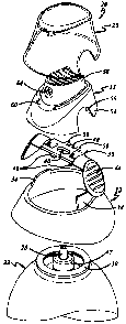
An actuator for an aerosol container (22) having a valve with a projecting valve stem (28) includes an actuator button (58) having an outlet (64) for coupling to the valve stem (28). A crossbar (36) is disposed between the container (22) and the actuator button (58). The crossbar (36) is movable with respect to the valve stem (28) between at least a center first position blocking depression of the actuator button (58) with respect to the valve stem (28) and spaced second positions on opposite sides of the first position permitting depression of the actuator button (58) with respect to the valve stem (28). The crossbar (36) preferably can be moved from either side of the actuator, and one or more springs (46) preferably are carried by the crossbar (36) for engaging the container (22) and biasing the crossbar (36) to the first or blocking position.


French Abstract

Un actionneur pour conteneur aérosol (22) disposant d'une soupape pourvue d'une tige de soupape saillante (28) comprend un bouton d'actionnement (58) muni d'un orifice de sortie (64) destiné à être couplé à la tige de la soupape (28). Une entretoise (36) est disposée entre le conteneur (22) et le bouton d'actionnement (58). L'entretoise (36) est mobile par rapport à la tige de soupape (28) et peut passer d'au moins une première position centrale empêchant d'abaisser le bouton d'actionnement (58) par rapport à la tige de soupape (28), à une deuxième position espacée sur les côtés opposés de la première position permettant d'abaisser le bouton d'actionnement (58) par rapport à la tige de la soupape (28). L'entretoise (36) peut de préférence être déplacée de chaque côté de l'actionneur et un ou plusieurs ressorts (46) sont de préférence portés par l'entretoise (36) pour venir en contact avec le conteneur (22) et pour polariser l'entretoise (36) sur la première position, à savoir sur la position de bloquage.

Claims

Note: Claims are shown in the official language in which they were submitted.


Claims
1.
An actuator for an aerosol container (22) having a valve with a projecting
valve stem
(28), said actuator including:
an actuator button (58) having an outlet (64) for coupling to the valve stem,
and
a crossbar (36) for disposition between the container and said actuator
button, said
crossbar being movable with respect to the valve stem between at least a
center first position
blocking depression of said actuator button with respect to said valve stem
and spaced second
positions on opposite sides of said first position permitting depression of
said actuator button with
respect to said valve stem,
characterized in that
said actuator button (58) has an internal rib (66) and said crossbar (36) has
a release
tab (48) that blocks said internal rib in said first position of said crossbar
and is spaced from said rib
in said second positions of said crossbar,
said rib (66) has a pair of side notches (68) facing in opposite directions,
said crossbar (36) has a pair of laterally spaced lock tabs (50) on opposite
sides of said
release tab, and
said crossbar is movable between said center first position, said spaced
second
positions, and spaced third positions on opposite sides of said second
positions at which one of said
lock tabs is received in a corresponding notch to lock said actuator button in
a depressed position.
7

2.
The actuator set forth in claim I wherein said crossbar (36) has a center
opening (40)
for receipt over the valve stem, and said release tab and said lock tabs
extend laterally with respect
to said center opening.
3.
The actuator set forth in claim 2 including springs (46) for engaging the
container and
biasing said crossbar to said center first position.
4.
The actuator set forth in claim 3 wherein said springs (46) are integrally
formed with
said crossbar (36).
5.
The actuator set forth in claim 4 wherein said crossbar includes integrally
formed
finger pads (44) on opposed ends of said crossbar.
6.
The actuator set forth in claim 1 including at least one spring (46) for
engaging the
container to bias said crossbar toward said center first position.
8

7.
The actuator set forth in.claim 6 wherein said at least one spring (46) is
integral with.
said crossbar (36).
8.
The actuator set forth in any preceding claim including a lower housing (32)
for
surrounding the valve stem and an upper housing (52) receivable on said lower
housing for enclosing
said crossbar (36), said crossbar extending through openings (56) on opposed
sides of said upper
housing.
9.
The -actuator set forth in claim 8 wherein said actuator button (58) is
integrally
coupled to said upper housing (52) by a pivot hinge (60).
10.
The actuator set forth in claim 9 wherein said lower housing (32) has
upstanding legs
(34) that partially block said openings in said upper housing.
9

Description

Note: Descriptions are shown in the official language in which they were submitted.


276-3080PCT
ACTUATOR FOR AN AEROSOL CONTAINER
The present disclosure relates to an'actuator for an aerosol container, such
as a spray paint can
for example, and more particularly to an aerosol actuator having a child-
resistance mechanism for releasably
blocking depression of the actuator button and/or a mechanism for releasably
locking the actuator button in
the depressed or activated position.
Background and Summary of the Disclosure
U. S. 4582228, 5282551 and 3828982, and DE 4400605 each disclose an actuator
for an
aerosol container having a valve with a projecting valve stem. An actuator
button has an outlet for coupling
to the valve stem. A crossbar is disposed between the container and the
actuator button, and is movable with
respect to the valve stem between a first position blocking depression of the
actuator button with respect to the
valve stem and a spaced second position permitting depression of the actuator
button with respect to the valve
stem.
A general-object of the present disclosure is to provide an actuator for an
aerosol container
that includes a child-resistance mechanism for=releasably blocking depression
of the actuator button and/or a
mechanism for releasably locking the actuator button in the depressed or
activated position.
The present disclosure embodies a numberofaspects that can be implemented
separately from
or in combination with each other.
An actuator for an aerosot, container having a valve with a projecting valve
stem, in
accordance with one aspect ofthe present disclosure, includes an actuator
button having an outlet for coupling
to the valve stem. A crossbar is disposed between the container and the
actuator button. The crossbar is
movable with respect to the valve stem between at least a.first position
blocking depression of the actuator
button with respect to the valve stem and a second position permitting
depression of the actuator button with
respect to the valve stem. The crossbar preferably can be moved from either
side of the actuator, and one or
more springs preferably are carried by the crossbar for engaging the container
and biasing the crossbar to the
first or blocking position. .
CA 02662590 2009-03-05

CA 02662590 2009-03-05
WO 2008/033207 PCT/US2007/018638
Brief Description of the Drawings
The disclosure, together with additional objects, features, advantages and
aspects
thereof, will best be understood from the following description, the appended
claims and the
accompanying drawings, in which:
FIG. l is a fragmentary perspective view of an aerosol container equipped with
an
actuator in accordance with an exemplary embodiment of the present disclosure;
FIG. 2 is a fragmentary exploded perspective view of the container and
actuator
illustrated in FIG. 1;
FIG. 3 is a perspective view of the package in FIGS. I and 2 with the cap and
upper
housing removed for purposes of illustration;
FIG. 4 is a perspective view of the upper housing in the package of FIGS. 1-3;
FIG. 5 is a perspective view of the interior of the upper housing in FIG. 4;
FIG. 6A is a perspective view of the actuator in a rest position, and FIG. 6B
i's a
fragmentary sectional view of the actuator in FIG. 6A;
FIG. 7A is a perspective view of the actuator with the actuator button being
released
for depression, and FIG. 7B is a fragmentary sectional view of the actuator in
FIG. 7A;
FIG. 8A is a fragmentary perspective view of the actuator with the actuator
button
released for depression, and FIG. 8B is a fragmentary sectional view of the
actuator in FIG. 8A; and
FIG. 9A is a fragmentary perspective view of the actuator in a depressed and
locked
position, and FIG. 9B is a fragmentary sectional view of the actuator in FIG.
9A.
2

CA 02662590 2009-03-05
WO 2008/033207 PCT/US2007/018638
Detailed Description of Preferred Embodiments
FIGS. 1-3 illustrate a package 20 in accordance with an exemplary embodiment
of
the present disclosure as including an aerosol container 22 with an actuator
24 and an overcap 26.
Aerosol container 22, which can be a spray paint container for example, has an
outlet valve with an
extending valve stem 28 surrounded by a collar 47 and a radially spaced ring
30. Actuator 24
preferably includes a lower housing 32 that is received over the end of
container 22 surrounding
valve stem 28. Lower housing 32 may be of molded plastic construction, for
example, and
preferably has a pair of diametrically opposed upstanding legs 34.
A crossbar or slide 36 is slidably disposed on and carried by collar 47 of
container
22. Crossbar 36 has a central body 38, which may be generally rectangular,
with an elongated or
slot-shaped center opening 40 received over valve stem 28. A leg 42 extends
from each opposed end
of center body 38 and a finger pad 44 is coupled to the remote end of each leg
42. A spring 46 is
carried by crossbar center body 38 inwardly adjacent to each leg 42,
preferably by being formed
integrally with center body 38 of crossbar 36. Springs 46 in the exemplary
embodiment internally
engage ring 30 on container 22 for biasing crossbar 36 to a center first
position illustrated in FIGS.
3 and 6B. As an alternative, the springs could engage collar 47 that surrounds
valve stem 28. The
springs could be made separately from crossbar 36 and assembled to the
crossbar. A release tab 48
is carried by center body 38 of crossbar 36, preferably in lateral alignment
with valve stem 28 at the
centered position of the crossbar illustrated in FIG. 3. Crossbar 36
preferably also includes a pair
of lock tabs 50 disposed on opposed sides of release tab 48. Lock tabs 50
preferably extend from
crossbar center body 38. Crossbar 36, including springs 46, preferably is of
one-piece integrally
molded plastic construction.
3

CA 02662590 2009-03-05
WO 2008/033207 PCT/US2007/018638
Actuator 24 also includes an upper housing 52, the details of which are best
seen in
FIGS. 4 and 5. Upper housing 52 includes a collar 54 having a pair of opposed
side openings 56.
Collar 54 may be secured by snap fit to lower housing 32 so as to enclose the
center portion of
crossbar 36, with the end portions of the crossbar extending through openings
56. Legs 34 on lower
housing 32 partially block openings 56 in assembly as shown for example in
FIG. 1. An actuator
button 58 is carried by collar 54, preferably by being integrally molded with
collar 54 and coupled
to collar 54 by an integral or living hinge 60. One or more outlet tubes 62 on
the underside of
actuator button 58 are coupled in assembly to valve stem 28 and feed the
contents of the container
to an outlet opening 64 when actuator button 58 depresses valve stem 28. A
boss or rib 66 extends
from the undersurface of actuator button 58. As best seen in FIG. 6B, the free
end of rib 66 overlies
the free end of release tab 48 on crossbar 36 when the crossbar is in the
first or centered position.
Rib 66 has a pair of oppositely facing side notches 68 disposed on respective
opposed sides of rib
66. When actuator button 58 is depressed, notches 68 are disposed to receive
lock tabs 50 on
crossbar 36, as will be described. Upper housing 52, including collar 54 and
actuator button 58;
preferably is of one-piece integrally molded plastic construction. Crossbar 36
is adapted to move
side-to-side with respect to the direction of outlet opening 64.
FIGS. 6A and 6B illustrate the neutral or rest position of actuator button 58
and
crossbar 36. Depression of actuator button 58 is inhibited by abutment of rib
66 against release tab
48, as shown in FIG. 6B. To release the actuator button, crossbar 36 is moved
longitudinally from
the center first position illustrated in FIGS. 3, 6A and 6B to a second
position offset from the first
position and illustrated in FIGS. 7A and 7B. (Inasmuch as crossbar 36
preferably is movable in both
directions, there will be two spaced second positions of the crossbar on
opposed sides of the center
4

CA 02662590 2009-03-05
WO 2008/033207 PCT/US2007/018638
first position.) In this second position, release tab 48 on crossbar 36 has
been moved out of the
blocking position with respect to rib 66 on actuator button 58, so that the
actuator button can now
be depressed to depress valve stem 28 and thereby activate the outlet valve of
aerosol container 22.
This depressed or activated position is illustrated in FIGS. 8A and 8B,
dispensing the contents of the
container.
In this depressed position of the actuator button illustrated in FIGS. 8A and
8B,
crossbar 36 can be moved to a third position illustrated in FIGS. 9A and 9B
spaced from the second
position illustrated in FIG. 7B. (Again, inasmuch as crossbar 36 preferably
can be moved
longitudinally in both directions, there preferably are two such third
positions of the crossbar
respectively spaced outwardly from the two second positions and the center
first position of the
crossbar.) In this third position of crossbar 36, one of the lock tabs 50 on
crossbar 36 moves into one
of the notches 68 on rib 66. Disposition of a lock tab 50 within a notch 68
prevents movement of
actuator pad 58, so that actuator pad 58 can be released by the user (FIG.
9A). (Again, there are
spaced lock tabs 50 on crossbar 36 and opposed notches 68 on rib 66 so that
actuator button 58 can
be locked by movement of crossbar 36 in either direction.) Actuator pad 58 can
then be released,
as illustrated in FIG. 9A, while holding crossbar 36 in the locked position,
which facilitates use by
an operator. However, if crossbar 36 is released, springs 46 on crossbar 36
will urge the crossbar
to the center first position, releasing finger pad 36 so that dispensing of
aerosol product is
terminated.
There thus has been disclosed an actuator for an aerosol container that fully
satisfies
all of the objects and aims previously set forth. The actuator has been
disclosed in connection with
an exemplary embodiment, and a number of modifications and variations have
been discussed.

CA 02662590 2009-03-05
WO 2008/033207 PCT/US2007/018638
Other modifications and variations readily will suggest themselves to persons
of ordinary skill in the
art in view of the foregoing description. The disclosure is intended to
embrace all such
modifications and variations as fall within the spirit and broad scope of the
appended claims.
6

Representative Drawing
A single figure which represents the drawing illustrating the invention.
Administrative Status

2024-08-01:As part of the Next Generation Patents (NGP) transition, the Canadian Patents Database (CPD) now contains a more detailed Event History, which replicates the Event Log of our new back-office solution.

Please note that "Inactive:" events refers to events no longer in use in our new back-office solution.

For a clearer understanding of the status of the application/patent presented on this page, the site Disclaimer , as well as the definitions for Patent , Event History , Maintenance Fee  and Payment History  should be consulted.

Event History

Description Date
Maintenance Fee Payment Determined Compliant 2024-08-06
Maintenance Request Received 2024-08-06
Inactive: IPC assigned 2023-10-20
Inactive: IPC expired 2023-01-01
Common Representative Appointed 2019-10-30
Inactive: Adhoc Request Documented 2014-08-06
Grant by Issuance 2012-08-07
Inactive: Cover page published 2012-08-06
Pre-grant 2012-05-23
Inactive: Final fee received 2012-05-23
Notice of Allowance is Issued 2012-05-03
Letter Sent 2012-05-03
Notice of Allowance is Issued 2012-05-03
Inactive: Approved for allowance (AFA) 2012-05-01
Letter Sent 2010-07-26
Request for Examination Received 2010-07-21
Request for Examination Requirements Determined Compliant 2010-07-21
All Requirements for Examination Determined Compliant 2010-07-21
Revocation of Agent Requirements Determined Compliant 2010-07-07
Inactive: Office letter 2010-07-07
Revocation of Agent Request 2010-03-05
Revocation of Agent Requirements Determined Compliant 2010-01-12
Inactive: Office letter 2010-01-12
Revocation of Agent Request 2009-12-08
Inactive: Cover page published 2009-07-08
Inactive: Notice - National entry - No RFE 2009-06-15
Inactive: First IPC assigned 2009-05-12
Application Received - PCT 2009-05-11
Inactive: IPRP received 2009-03-06
National Entry Requirements Determined Compliant 2009-03-05
Application Published (Open to Public Inspection) 2008-03-20

Abandonment History

There is no abandonment history.

Maintenance Fee

The last payment was received on 2011-07-28

Note : If the full payment has not been received on or before the date indicated, a further fee may be required which may be one of the following

  • the reinstatement fee;
  • the late payment fee; or
  • additional fee to reverse deemed expiry.

Patent fees are adjusted on the 1st of January every year. The amounts above are the current amounts if received by December 31 of the current year.
Please refer to the CIPO Patent Fees web page to see all current fee amounts.

Owners on Record

Note: Records showing the ownership history in alphabetical order.

Current Owners on Record
MASTERCHEM INDUSTRIES LLC
Past Owners on Record
DARREN STODDART
MICHAEL HERSCHEL REEDY
RAVI ITIRAVIVONG
ROBIN SPENCE
TAIWON CHOI
Past Owners that do not appear in the "Owners on Record" listing will appear in other documentation within the application.
Documents

To view selected files, please enter reCAPTCHA code :


To view images, click a link in the Document Description column. To download the documents, select one or more checkboxes in the first column and then click the "Download Selected in PDF format (Zip Archive)" or the "Download Selected as Single PDF" button.

List of published and non-published patent-specific documents on the CPD .

If you have any difficulty accessing content, you can call the Client Service Centre at 1-866-997-1936 or send them an e-mail at CIPO Client Service Centre.


Document
Description 
Date
(yyyy-mm-dd) 
Number of pages   Size of Image (KB) 
Description 2009-03-04 6 243
Drawings 2009-03-04 5 180
Abstract 2009-03-04 2 82
Representative drawing 2009-06-15 1 10
Claims 2009-03-04 5 128
Claims 2009-03-05 3 77
Confirmation of electronic submission 2024-08-05 2 70
Notice of National Entry 2009-06-14 1 192
Acknowledgement of Request for Examination 2010-07-25 1 178
Commissioner's Notice - Application Found Allowable 2012-05-02 1 163
Notice: Maintenance Fee Reminder 2015-05-25 1 121
Notice: Maintenance Fee Reminder 2016-05-24 1 120
Notice: Maintenance Fee Reminder 2017-05-23 1 121
Notice: Maintenance Fee Reminder 2018-05-23 1 119
Notice: Maintenance Fee Reminder 2019-05-26 1 120
PCT 2009-03-04 11 395
PCT 2009-03-05 2 74
Correspondence 2009-12-07 2 57
Correspondence 2010-01-11 1 15
Correspondence 2010-01-11 1 17
Correspondence 2010-03-04 3 65
Correspondence 2010-07-06 1 13
Correspondence 2010-07-06 1 16
PCT 2009-03-05 9 332
Correspondence 2012-05-22 3 75