Language selection

Search

Patent 2662861 Summary

Third-party information liability

Some of the information on this Web page has been provided by external sources. The Government of Canada is not responsible for the accuracy, reliability or currency of the information supplied by external sources. Users wishing to rely upon this information should consult directly with the source of the information. Content provided by external sources is not subject to official languages, privacy and accessibility requirements.

Claims and Abstract availability

Any discrepancies in the text and image of the Claims and Abstract are due to differing posting times. Text of the Claims and Abstract are posted:

  • At the time the application is open to public inspection;
  • At the time of issue of the patent (grant).
(12) Patent Application: (11) CA 2662861
(54) English Title: ROTARY PRODUCT ACCUMULATOR
(54) French Title: ACCUMULATEUR DE PRODUITS ROTATIF
Status: Deemed Abandoned and Beyond the Period of Reinstatement - Pending Response to Notice of Disregarded Communication
Bibliographic Data
(51) International Patent Classification (IPC):
  • B65G 29/00 (2006.01)
  • B65G 37/00 (2006.01)
  • B65G 47/00 (2006.01)
  • B65G 47/51 (2006.01)
(72) Inventors :
  • JONES, ARTHUR K. (United States of America)
(73) Owners :
  • CURRAN MANUFACTURING CORPORATION
(71) Applicants :
  • CURRAN MANUFACTURING CORPORATION (United States of America)
(74) Agent: SMART & BIGGAR LP
(74) Associate agent:
(45) Issued:
(86) PCT Filing Date: 2007-09-06
(87) Open to Public Inspection: 2008-03-13
Availability of licence: N/A
Dedicated to the Public: N/A
(25) Language of filing: English

Patent Cooperation Treaty (PCT): Yes
(86) PCT Filing Number: PCT/US2007/077729
(87) International Publication Number: US2007077729
(85) National Entry: 2009-03-05

(30) Application Priority Data:
Application No. Country/Territory Date
60/842,501 (United States of America) 2006-09-06

Abstracts

English Abstract

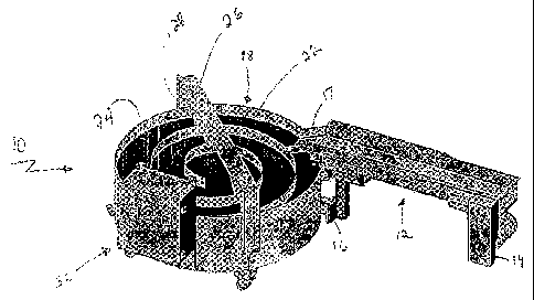
A stand-alone parts accumulator that can be retrofit as a unitary add-on to an existing production line. The parts accumulator includes: (a) a generally linear conveyor; (b) a rotary table comprising a spiral barrier guide defining a path from an outer region of the table to an inner region of the table; (c) a connector attaching the linear conveyor to the rotary table; (d) a motor connected to rotate the rotary table; (e) an adjustable controller connected to the motor to control rotation of the table. A single bracket can be used to support the conveyor in either a left-hand or a right-hand configuration. The conveyor motor is positioned substantially within the footprint of the conveyor. The conveyor is narrow (between about 2 inches and about 8 inches).


French Abstract

La présente invention concerne un accumulateur de pièces autonome qui peut être installé en tant qu'élément supplémentaire unitaire dans une ligne de fabrication existante. L'accumulateur de pièces comprend : (a) a convoyeur généralement linéaire ; (b) une table rotative comprenant un guide d'arrêt en spirale définissant une trajectoire d'une région externe de la table vers une région interne de la table ; (c) un connecteur fixant le convoyeur linéaire à la table rotative ; (d) un moteur raccordé afin de mettre en rotation la table rotative ; (e) un dispositif de commande réglable raccordé au moteur afin de commander la rotation de la table. Un seul support peut être utilisé pour supporter le convoyeur dans une configuration à gauche ou à droite. Le moteur du convoyeur est positionné sensiblement à l'intérieur de l'espace occupé au sol par le convoyeur. Le convoyeur est étroit (entre environ 5 cm (2 pouces) et environ 20 cm (8 pouces)).

Claims

Note: Claims are shown in the official language in which they were submitted.


WHAT IS CLAIMED IS:
1. A stand-alone unitary parts accumulator/conveyor assembly comprising
(a) a generally linear conveyor;
(b) a rotary table comprising a spiral barrier guide defining a path from an
outer region of
the table to an inner region of the table;
(c) a connector attaching the linear conveyor to the rotary table;
(d) a motor connected to rotate the rotary table;
(e) an adjustable controller connected to the motor to control rotation of the
table.
2. The parts accumulator/conveyor assembly of claim 1 in which the controller
is
independently powered.
3. The parts accumulator/conveyor assembly of claim 1 further comprising a
second motor
connected to more the generally linear conveyor.
4. The parts accumulator/conveyor assembly of claim 1 further comprising a
weir positioned
to meter movements of parts toward the center of the path.
5. The parts accumulator/conveyor assembly of claim l in which the weir
comprises a
stationary bar extending over the table with arms extending from the bar into
the path.
6. The parts accumulator/conveyor assembly of claim 1 comprising a bracket
supporting the
generally linear conveyor.
7. The parts accumulator/conveyor assembly of claim 1 in which the conveyor is
between 2"
and 8" wide.
8. A stand-alone unitary parts accumulator/conveyor assembly comprising
(a) a generally linear conveyor and a conveyor motor to drive the conveyor;
(b) a parts accumulator for capturing the parts transported by the conveyor;
6

(c) a reversible bracket mounting the conveyor, the bracket comprising:
(1) a plate for mounting the bracket,
(2) an support attached to the plate at an angle, the support including a
first surface
and a second surface generally opposite and spaced from the first surface
(3) a conveyor cradle attached to either the first support surface or the
second support
surface,
(d) wherein the first surface includes a first feature sized and shaped to
cooperate with a
fastener to position the cradle in a first position, parallel to, and facing
away from, the
first surface, and the second surface includes a second feature sized and
shaped to
cooperate with a fastener to position the cradle in a second position,
parallel to, and
facing away from, the second surface, whereby the cradle may be fastened
either to
the first surface in the first position or to the second surface in the second
position.
9. The parts accumulator conveyor assembly of claim 8 in which the parts
accumulator
comprises a rotary table comprising a spiral barrier guide defining a path
from an outer
region of the table to an inner region of the table; and the accumulator
comprises,
(a) a motor connected to rotate the rotary table;
(b) an adjustable controller connected to the motor to control rotation of the
table.
10. The parts accumulator conveyor assembly of claim 9 in which the conveyor
has a width of
between 2 inches and 8 inches.
11. A stand-alone unitary parts accumulator/conveyor assembly comprising
(a) a generally linear conveyor and a conveyor motor to drive the conveyor;
(b) a parts accumulator for capturing the parts transported by the conveyor;
a motor mounted to drive the conveyor, the conveyor having a width between 2
inches
and 8 inches.
12. The conveyor of claim 11 in which the a mount of dead space on each side
of the conveyor
is 1 inch or less.
7

13. The conveyor or claim 11 in which the ratio of the dead space to the
conveyor belt width is
greater than 8 inches.
14. A stand-alone unitary parts accumulator/conveyor assembly comprising
(a) a generally linear conveyor and a conveyor motor to drive the conveyor;
(b) a parts accumulator for capturing the parts transported by the conveyor;
(c) a motor mounted to drive the conveyor, the motor being positioned
substantially
within the footprint of the conveyor.
15. The parts accumulator conveyor assembly of claim 14 in which the conveyor
belt width is
less than 8 inches.
8

Description

Note: Descriptions are shown in the official language in which they were submitted.


CA 02662861 2009-03-05
WO 2008/030937 PCT/US2007/077729
Rotary Product Accumulator
CROSS-ItEFERENCE TO I2ELATED APPLICATIONS
This application claims priority to U.S. Application Serial No. 60/842,501,
filed on
Septeniber 6, 2006.
TECHNICAL FIELD
This invention is in the general field ofproduction lines, particularly
apparatus that
catches and stores parts on such lines.
BACKGROUND
Parts catchers or parts accumulators collect parts from production lines.
Typically the
parts are finished parts produced by fc;eding raw material, sucli as material
in bar form, to a
lathe. The lathe machines the raw material, shaping and cutting ofI'a
complete, or near
complete part, which is then stored in the parts catcher. Often the parts
catcher is simply a
bucket on some type of inovable ann that can extend at the proper time via the
machine control
so as to catch the work piece to be stored. After receiving the part from the
lathc, the parts
catcher retracts and deposits the work piece through an opening in the machine
guarding either
into a collection box on the front of the machine, or onto a straight
conveyor, typically 3-4 feet
in length. Then the machine can continue making the next piece.
Some parts catchers have very limited storage space, and hence they provide
only a
short amount of unmanned runtime, and/or they present a strong possibility of
dainaging the
tinishcd parts as they bang together. Such limitations presented by the parts
catcher undennine
one of the sil;nificant advantages of bar feeding - extended periods of
urunanned run time.
Parts accumulators can be large and the space they occupy can interfere with
efficiency.
SUMMARY
The invention generally features a stand-alone parts accumulator that can be
retrofit as a
unitary add-on to an existing production line. The parts accumulator includes:
(a) a generally
linear conveyor; (b) a rotary table comprising a spiral barrier guide defining
a path froin an
outer region of the table to an inner region of the table; (e) a connector
attaching the linear
1

CA 02662861 2009-03-05
WO 2008/030937 PCT/US2007/077729
conveyor to the rotary table; (d) a motor connected to rotate the rotary
table; (e) aii adjustable
controller connected to the motor to controlrotation of the table.
I'referred embodiments may include other features. For example, the controller
may be
independently powered. A second motor may be connected to more the generally
linear
conveyor. A weir (e.g., a stationary bar extending over the table with arms
extending from the
bar into the path) may be positioned to meter movements of parts toward the
center of the path.
A bracket supports the generally linear conveyor to attach it to the rotary
table.
A second aspect of the invention, which can be combined with the f rst aspect
or
cmployed independently, features a reversible bracket mounting the conveyor.
'I'he same
bracket can be uscxi for either left-hand or right-hand installations, and
there is no need to
disassemble (reconfigure) the drive when switching between left hand and right
hand drive; nor
is there any ncecl to reconfigure the drive or to reverse themotor when
switching between lelt;
hand aiid right hand drive. The bracket is positioned substantially within the
periphery of the
conveyor, so it does not obstruct access to the conveyor when the conveyor is
not being used.
When combined with the above-described rotary accumulator, the assembly
presents a coinpact
package.
A third aspect of the invention, which also can be used alone or combined
witli any one
or more of the other aspects, features positioning the conveyor motor within
the "footprint" of
the conveyor, meaning that the motor does not increase the effective width of
the overall
device. The advantages of this include:
a) better weight balance, reducing the degree of support required for tlie
conveyor and
therefore the complexity of the conveyor mounting;
b) improved belt life by use of a belt drive that pulls the belt rather than
pushing it;
c) improved ability to use the conveyor in tight spaces, by removal of
obstructions from
the working end of the conveyor; and
d) improved access to machine components such as foot pedals and oil fill
points.
The invention thus permits the use of a separate motor to drive the conveyor
without a
substantial sacrifice ofconvenience or access to the conveyor, and without
substantially
increasing the footprint of the entire assembly.
2

CA 02662861 2009-03-05
WO 2008/030937 PCT/US2007/077729
In a fourtli aspect of the invention, which also can be combiiled with eithcr
or botli of
the first two aspects,, the conveyor width is between about 2" and 8".
Preferably, the amount of
dead space on each side is I inch or less. This feature also tnakes access to
the machine easier.
"1'he details of one or more embod'unents of the invention are set forth in
the accompa-
nying drawings and the description below. Other features, objects, and
advantages of the
inventiort will be apparent from the description and drawings, and from the
claims.
DESCRIPTION OF DRAWINGS
FIG I is a perspective view of a rotary (spiral) accumulator according to the
invention.
I IG. 2 is a perspective view of a rotary (spiral) accumulator with sections
cut away to
show additional features.
FIGS. 3 and 4 respectively are views of the same conveyor mounting bracket,
showing
that it can be used in both left- and right-hand configurations.
FIG 5 is a view of a motor mounted for operatifln with a conveyor belt
FIG 6 is a view of the conveyor belt and inotor assembled witli the product
accumulator.
Like reference symbols in the various drawings indicate like elements.
DETAILED DESCTtIPTION
In Fig. 1, rotary accumulator 10 includes a linear conveyor 12, supported at
the front
etid by stand 14. At the other end, the conveyor is attached by bracket 16 to
a rotary table 18.
A ramp 17 provides a connecting path for parts to travel from conveyor 12 onto
table 18.
Table 18 includes a spiral wall 22 forming a path 24 on thetop of rotary table
18 in
wliich parts can accumulate in a relatively compact area. Weir 26 includes
triangular arins 28
extending downwardly into path 24 to control the movement of parts along path
24.
A controller 30 includes a. connection for power and electronic controls for
motor 32
whicli is connected to rotate table 18. The electronic controls manually
control the speed at
which table 18 rotates. Controller 30 also controls motor 33 which drives
linear conveyor 12
so that the speed of conveyor 12 matclies the speed at which table 18 rotates.
An adjustable
timer in controller 30 is set to match the machine tools cycle time. Conveyor
12 is an integral.
part or the accuinulator 10, simplifying the installation of the accumulator
onto the production
line.
3

CA 02662861 2009-03-05
WO 2008/030937 PCT/US2007/077729
In operation, a production line (e.g. having a lathe), deposits parts on
linear conveyor
12. Drivcn by motor 33, convcyor 12 moves the parts to ramp 17 and then onto
table 18. The
speed of rotation of table 18 and the speed of conveyor 12 are controlled by
controller 30, so
that parts are accumulated in the spiral path on table 18 at a desired rate.
The weir 26 is
stationary. As table 18 rotates, arms 28 contact the parts and move them
toward the center of
the spiral in an orderly way, with the parts added earlier being located at
the center of thc spiral
and the later added parts being located at the periphery. When the path is
loaded with parts,
accumulator 10 is emptied for the next machine tool cycle.
As noted, there are advantages to driving the product accumulator with a motor
that is
separate froni the conveyor motor. For example the stand-alone accumulator
with its own
motor can be more casily attached and detached.
Figs 3 and 4 show a conveyor-mounting bracket having 40 tliree parts: a
support 42
connecting a slanted plate 44 to a conveyor mounting cradlc 46. The same parts
are used in
both Figs 3 and 4. The only difference between the figures is that cradle 46
has been moved
from one side to thc other. In that way, the bracket holds the conveyor either
in a left-hand
configuration (Fig. 3) or a right-hand configuration (Fig. 4). To switch
bctween these
configurations, it is only necessary to remove bolts holding the cradle 46 to
support 42 and to
then move the cradle to the other side of support 42.
In Fig. 5, motor 48 is mounted to a plate 50 attached to a bridge 52 over the
conveyor
54. Motor 48 does not extend beyond the footprint of conveyor 54, so it does
not expand the
footprint of the conveyor/motor asseinbly. The accuinulator is not shown.
Fig. 6 is a view of the entire assembly: the conveyor; the inotor and
controller; and the
accumulator. The overall width of the conveyor is relatively narrow and its
footprint is not
substantially increased by the motor, enabling the operator to have easy
access to the conveyor
and motor. Even with the parts accumulator added, access to critical areas
around the assembly
are generally unobstructed.
Drive roller 56 is inboard (past) motor 48. As a result, the motor pulls the
conveyor
rather than pushes it, wliich is generally a inore efficient design as it
reduces the tendency for
the conveyor belt to buckle when parts of significant weight are being
conveyed. The invention
achieves this design while reniaining compact.
4

CA 02662861 2009-03-05
WO 2008/030937 PCT/US2007/077729
A nuinber of embodiments of the invention have been described. Nevertheless,
it will
be understood that various modifications may be made without departing from
the spirit and
scope of the invention.
s

Representative Drawing
A single figure which represents the drawing illustrating the invention.
Administrative Status

2024-08-01:As part of the Next Generation Patents (NGP) transition, the Canadian Patents Database (CPD) now contains a more detailed Event History, which replicates the Event Log of our new back-office solution.

Please note that "Inactive:" events refers to events no longer in use in our new back-office solution.

For a clearer understanding of the status of the application/patent presented on this page, the site Disclaimer , as well as the definitions for Patent , Event History , Maintenance Fee  and Payment History  should be consulted.

Event History

Description Date
Time Limit for Reversal Expired 2012-09-06
Application Not Reinstated by Deadline 2012-09-06
Deemed Abandoned - Failure to Respond to Maintenance Fee Notice 2011-09-06
Amendment Received - Voluntary Amendment 2010-01-22
Inactive: Office letter 2009-07-20
Letter Sent 2009-07-20
Inactive: Cover page published 2009-07-09
Inactive: Correspondence - PCT 2009-06-02
IInactive: Courtesy letter - PCT 2009-05-27
Inactive: Notice - National entry - No RFE 2009-05-27
Inactive: Declaration of entitlement - PCT 2009-05-26
Inactive: Single transfer 2009-05-26
Inactive: IPC assigned 2009-05-14
Application Received - PCT 2009-05-12
National Entry Requirements Determined Compliant 2009-03-05
Application Published (Open to Public Inspection) 2008-03-13

Abandonment History

Abandonment Date Reason Reinstatement Date
2011-09-06

Maintenance Fee

The last payment was received on 2010-08-19

Note : If the full payment has not been received on or before the date indicated, a further fee may be required which may be one of the following

  • the reinstatement fee;
  • the late payment fee; or
  • additional fee to reverse deemed expiry.

Patent fees are adjusted on the 1st of January every year. The amounts above are the current amounts if received by December 31 of the current year.
Please refer to the CIPO Patent Fees web page to see all current fee amounts.

Fee History

Fee Type Anniversary Year Due Date Paid Date
Basic national fee - standard 2009-03-05
Registration of a document 2009-05-26
MF (application, 2nd anniv.) - standard 02 2009-09-08 2009-09-08
MF (application, 3rd anniv.) - standard 03 2010-09-07 2010-08-19
Owners on Record

Note: Records showing the ownership history in alphabetical order.

Current Owners on Record
CURRAN MANUFACTURING CORPORATION
Past Owners on Record
ARTHUR K. JONES
Past Owners that do not appear in the "Owners on Record" listing will appear in other documentation within the application.
Documents

To view selected files, please enter reCAPTCHA code :


To view images, click a link in the Document Description column (Temporarily unavailable). To download the documents, select one or more checkboxes in the first column and then click the "Download Selected in PDF format (Zip Archive)" or the "Download Selected as Single PDF" button.

List of published and non-published patent-specific documents on the CPD .

If you have any difficulty accessing content, you can call the Client Service Centre at 1-866-997-1936 or send them an e-mail at CIPO Client Service Centre.

({010=All Documents, 020=As Filed, 030=As Open to Public Inspection, 040=At Issuance, 050=Examination, 060=Incoming Correspondence, 070=Miscellaneous, 080=Outgoing Correspondence, 090=Payment})


Document
Description 
Date
(yyyy-mm-dd) 
Number of pages   Size of Image (KB) 
Drawings 2009-03-04 5 1,401
Abstract 2009-03-04 1 111
Description 2009-03-04 5 240
Claims 2009-03-04 3 96
Representative drawing 2009-07-08 1 62
Reminder of maintenance fee due 2009-05-26 1 111
Notice of National Entry 2009-05-26 1 193
Courtesy - Certificate of registration (related document(s)) 2009-07-19 1 102
Courtesy - Abandonment Letter (Maintenance Fee) 2011-10-31 1 173
Reminder - Request for Examination 2012-05-07 1 118
PCT 2009-03-04 3 145
Correspondence 2009-05-26 1 17
Correspondence 2009-06-01 1 43
Correspondence 2009-05-25 4 117
Correspondence 2009-07-19 1 15
Fees 2009-09-07 1 35