Language selection

Search

Patent 2663355 Summary

Third-party information liability

Some of the information on this Web page has been provided by external sources. The Government of Canada is not responsible for the accuracy, reliability or currency of the information supplied by external sources. Users wishing to rely upon this information should consult directly with the source of the information. Content provided by external sources is not subject to official languages, privacy and accessibility requirements.

Claims and Abstract availability

Any discrepancies in the text and image of the Claims and Abstract are due to differing posting times. Text of the Claims and Abstract are posted:

  • At the time the application is open to public inspection;
  • At the time of issue of the patent (grant).
(12) Patent: (11) CA 2663355
(54) English Title: TAPERED ROLLER BEARING WITH IMPROVED CAGE
(54) French Title: PALIER A ROULEAUX CONIQUES AVEC CAGE AMELIOREE
Status: Granted
Bibliographic Data
(51) International Patent Classification (IPC):
  • F16C 33/46 (2006.01)
  • B61F 15/12 (2006.01)
  • F16C 19/38 (2006.01)
  • F16C 19/50 (2006.01)
  • F16C 33/56 (2006.01)
(72) Inventors :
  • MASON, MICHAEL (United States of America)
  • REED, MARTIN E. (United States of America)
(73) Owners :
  • AMSTED RAIL COMPANY, INC. (United States of America)
(71) Applicants :
  • AMSTED RAIL COMPANY, INC. (United States of America)
(74) Agent: GOWLING WLG (CANADA) LLP
(74) Associate agent:
(45) Issued: 2010-12-14
(22) Filed Date: 2009-04-20
(41) Open to Public Inspection: 2010-04-20
Examination requested: 2009-04-20
Availability of licence: N/A
(25) Language of filing: English

Patent Cooperation Treaty (PCT): No

(30) Application Priority Data:
Application No. Country/Territory Date
12/288296 United States of America 2008-10-20

Abstracts

English Abstract

A bearing assembly is provided having a roller bearing with an inner race fitted around the journal portion of an axle. An outer raceway combines with the inner raceway to receive roller elements. A backing ring is centered to the shaft fillet. Tapered roller elements are located between and contact the inner and outer raceways. A cage is comprised of an inner ring, and outer ring, and a plurality of pocket bars and support pocket bars extending between the inner and outer rings. The support pocket bars have an overall greater thickness than the pocket bars. The cage is a generally unitary structure comprised of a nylon resin material with a fiber fill.


French Abstract

Un élément d'assemblage est fourni et est doté d'un roulement à rouleaux avec une enveloppe interne ajustée autour de la partie tourillon d'un essieu. Un chemin de roulement externe se combine à un chemin de roulement interne pour recevoir les éléments à rouleaux. Une bague support est centrée sur le filet de l'arbre. Les éléments de roulement coniques se trouvent entre les chemins de roulement interne et externe et entrent en contact avec ces derniers. Une cage compte une bague intérieure et une bague extérieure, ainsi que plusieurs barres de poche et de barres de poche de soutien qui s'étendent entre les bagues intérieure et extérieure. Les barres de poche de soutien sont généralement plus épaisses que les barres de poche. La cage est habituellement une structure se composant d'une résine de nylon avec des fibres de rembourrage.

Claims

Note: Claims are shown in the official language in which they were submitted.


CLAIMS

What is claimed is:


1. A tapered roller bearing assembly comprising,

an inner race having an outwardly directed raceway thereon, an outer race
having an
inwardly directed raceway thereon, and tapered roller elements located between
and contacting
the inner and outer raceways,

and a cage to provide spacing and alignment for the roller elements,
the cage having a generally cylindrical structure,

and comprised of an inner ring and an outer ring,

and a plurality of pocket bars extending between the inner ring and the outer
ring, and a
plurality of support pocket bars extending between the inner ring and the
outer ring, wherein
each support pocket bar has an overall thickness greater than an overall
thickness of each pocket
bar.

2. The tapered roller bearing assembly of claim 1

wherein each pocket bar has a base section attached to the inner ring, and
wherein an
overall thickness of each pocket bar is less than a thickness of the base
section of the pocket
bar.


-7-


3. The tapered roller bearing assembly of claims 1,

wherein each support pocket bar has a base section attached to the inner ring,
wherein an
overall thickness of each support pocket bar is, for a majority of its length,
about the same as a
thickness of the base section of the support pocket bar base section.

4. The tapered roller bearing assembly of claim 1,

wherein each pocket bar has a base section attached to the inner ring, and
wherein an
overall thickness of each pocket bar is less than a thickness of the base
section of the base section
of the pocket bar,

and wherein each support pocket bar has a base section attached to the inner
ring,
wherein an overall thickness of each support pocket bar is, for a majority of
its length, about the
same as a thickness of the base section of the support pocket bar base
section.

5. The tapered roller bearing assembly of claim 1,

wherein each pocket bar has a base section attached to the inner ring, and
wherein each
pocket bar is tapered in its thickness from the base section such that the
overall thickness of each
pocket bar is less than a thickness of the base section of the pocket bar.

6. The tapered roller bearing assembly of claim1,

wherein the cage is a generally unitary structure comprised of a resin
material with a fill
of glass fibers.


-8-


7. The tapered roller bearing assembly of claim 6,

wherein the resin material is a nylon and glass fibers in the fill are
generally over 10mm
in length.

8. The tapered roller bearing assembly of claim 6,

wherein the glass fiber fill comprises at least 25% of the weight of the resin
material.
9. The tapered roller bearing of claim1,

wherein the case is injection molded with a nylon resin material filled with
at least 25%
by weight of glass fibers of at least 10mm in length.

10. A tapered roller bearing assembly comprising

an inner race having an outwardly directed raceway thereon,

an outer race having an inwardly directed raceway therein, and tapered roller
elements
located between and contacting the inner and outer raceways,

and a cage to provide spacing and alignment for the roller elements, the case
having a
generally cylindrical structure and comprised of an inner ring and an outer
ring and a plurality of
pocket bars extending between the inner ring and the outer ring,

and a plurality of support pocket bars extending between the inner ring and
the outer ring,
wherein each support pocket bar has an overall thickness greater than an
overall thickness
of each pocket bar,

and wherein the cage is a generally unitary structure comprised of a resin
material with a
fill of glass fibers.


-9-


11. The tapered roller bearing assembly of claim 10

wherein each pocket bar has a base section attached to the inner ring and
wherein an
overall thickness of each pocket bar is less than a thickness of the base
section of the pocket bar.
12. The tapered roller bearing assembly of claim 10

wherein each support pocket bar has a base section attached to the inner ring,
wherein an
overall thickness of each support pocket bar is, for a majority of its length,
about the same as a
thickness of the base section of the support pocket bar base section.

13. The tapered roller bearing assembly of claim 10

wherein each pocket bar has a base section attached to the inner ring, and
wherein an
overall thickness of each pocket bar is less than a thickness of the base
section of the base section
of the pocket bar,

and wherein each support pocket bar has a base section attached to the inner
ring,
wherein an overall thickness of each support pocket bar is, for a majority of
its length, about the
same as a thickness of the base section of the support pocket bar base
section.

14. The tapered roller bearing assembly of claim 10

wherein each pocket bar has a base section attached to the inner ring, and
wherein each
pocket bar is tapered in its thickness from the base section such that the
overall thickness of each
pocket bar is less than a thickness of the base section of the pocket bar.


-10-


15. The tapered roller bearing assembly of claim 10

wherein the resin material is a nylon and the glass fibers in the fill are
generally over
10mm in length.

16. The tapered roller bearing assembly of claim 10

wherein the glass fiber fill comprises at least 25% of the weight of the nylon
resin
material.

17. The tapered roller bearing of claim 10

wherein the cage is injection molded with a nylon resin material filled with
at least 25%
by weight of glass fibers of at least 10mm in length.

18. The tapered roller bearing assembly comprising

an inner race having an outwardly directed raceway thereon,
an outer race having an inwardly directed raceway thereon,

and tapered roller elements located between and contacting the inner and outer
raceways,
and a cage to provide spacing and alignment for the roller elements, the cage
having a
generally cylindrical structure and comprised of an inner ring and an outer
ring and a plurality of
pocket bars extending between the inner ring and the outer ring,

and a plurality of support pocket bars extending between the inner ring and
the outer ring,
wherein each support pocket bar has a thickness greater than a thickness of
each pocket
bar,


~11~


and wherein the cage is a generally unitary structure comprised of a nylon
resin material
with a fill of glass fibers,

wherein each pocket bar has a base section attached to the inner ring, and
wherein an
overall thickness of each pocket bar is less than thickness of the base
section of the base section
of the pocket bar,

and wherein each support pocket bar has a base section attached to the inner
ring,
wherein an overall thickness of each support pocket bar is, for a majority of
its length, about the
same as a thickness of the base section of the support pocket bar base
section.

19. The tapered roller bearing assembly of claim 18

wherein the potential cage vibration of less than 0.03 inch.
20. The tapered roller bearing assembly of claim 18

wherein the glass fiber fill comprises at least 25% of the weight of the nylon
resin
material and are generally over 10mm in length.


-12-

Description

Note: Descriptions are shown in the official language in which they were submitted.


CA 02663355 2009-04-20

Case: BRN024
TAPERED ROLLER BEARING WITH IMPROVED CAGE

BACKGROUND OF THE INVENTION

This invention relates to tapered roller bearings and more particularly to an
improved
cage for such tapered roller bearings for use in a railcar.

Roller bearing assemblies incorporating two rows of tapered roller bearings
preassembled
into a self-contained, pre-lubricated package for assembly onto journals at
the ends of axles or
shafts are known. Such bearing assemblies are used as rail car bearings
assembled onto journals
at the ends of the car axles. Bearings of this type typically employ two rows
of tapered roller
bearings fitted one into each end of a common bearing cup with their
respective bearing cones

having an inner diameter dimensioned to provide an interference fit with the
shaft journal and a
cylindrical sleeve or spacer positioned between the cones providing accurate
spacing on the
journal. A cage keeps the tapered roller bearings in each row spaced from each
other and
properly aligned. Seals mounted within each end of the bearing cup provide
sealing contact with
wear rings bearing against the outer ends of the respective bearing cones at
each end of the

assembly.

In a typical rail car installation, the axle journal is machined with a fillet
at the inboard
end, and a backing ring having a surface complementary to the contour of the
fillet and an
abutment surface for engaging the inboard end of the inner wear ring
accurately positions the
bearing assembly on the journal. An end cap mounted on the end of the axle by
bolts threaded

into bores in the end of the axle engages the outboard wear ring and clamps
the entire assembly
on the end of the axle. The wear rings typically have an inner diameter
dimensioned to provide
an interference fit with the journal over at least a portion of their length
so that the entire
assembly is pressed as a unit onto the end of the journal shaft.

- I-


CA 02663355 2009-04-20

Case: BRN024
25 SUMMARY OF THE INVENTION

The tapered roller bearing assembly includes an inner race or cone fitted
around the
journal portion of the axle or shaft. The inner race includes an outwardly
directed raceway. An
outer race or cup has an inwardly directed raceway. Roller elements are
located between and
contacting the inner and outer raceways. A cage is a unitary structure that
keeps the roller

30 elements spaced from each other and aligned. The cage is comprised of a
nylon or a polymer,
with fiber filler material and has an improved design with strengthened
support pocket bars.
A backing ring has a contoured surface complementary to and engaging the
contoured

surface of a fillet formed on the shaft. The fillet leads from the journal to
the shoulder of the
shaft. The contoured surfaces cooperate to fix the backing ring against axial
movement along the
35 shaft. An annular wear ring is interposed between and engages the inner
race and the backing
ring.

BRIEF DESCRIPTION OF THE DRAWINGS
In the drawings,

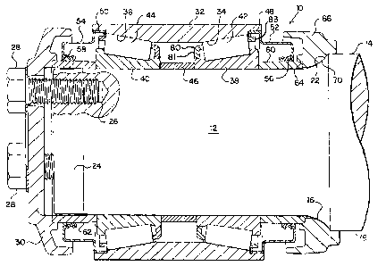
Fig. 1 is a sectional view of a shaft journal having mounted thereon a tapered
roller
40 bearing assembly in accordance with the present invention;

Fig. 2 is a perspective view of a cage for a tapered roller bearing assembly
in accordance
with an embodiment of the present invention, and

Fig. 3 is a partial, detailed view of a cage for a tapered roller bearing
assembly in
accordance with an embodiment of the present invention.


DESCRIPTION OF THE PREFERRED EMBODIMENTS
- 2-


CA 02663355 2009-04-20

Case: BRN024
Referring now to Fig. 1 of the drawings, a tapered roller bearing assembly
indicated
generally by the reference numeral 10 on Fig. 1 is shown mounted on a journal
12 on the free,
cantilevered end of a shaft or axle 14, typically a rail car axle. Journal 12
is machined to very

50 close tolerances and terminates at its inner end in a contoured fillet
221eading to a cylindrical
shoulder 18 of axle 14. At the free end of the axle, journal portion 12
terminates in a slightly
conical or tapered guide portion 24 dimensioned to facilitate installation of
the bearing assembly
onto the journal. A plurality of threaded bores 26 are formed in the end of
axle 14 for receiving
threaded cap screws, or bolts 28 for mounting a bearing retaining cap 30 on
the end of the shaft

55 to clamp the bearing in position as described more fully herein below.

The tapered roller bearing assembly 10 is preassembled before being mounted
and
clamped on journal 12 by cap 30. The tapered roller bearing assembly includes
a unitary bearing
cup or outer raceway 32 having a pair of raceways 34, 36 formed one adjacent
each end thereof
which cooperate with a pair of bearing cones 38, 40, respectively, to support
the two rows of

60 tapered rollers 42, 44, respectively, there between. A center spacer 46 is
positioned between
cones 38, 40 to maintain the cones in accurately spaced relation relative to
one another.

The bearing cup 32 is provided with cylindrical counterbores 48, 50 at its
opposite ends
outboard of the raceways 34, 36, and a pair of seal assemblies 52, 54 are
pressed one into each of
the cylindrical counterbores 48, 50. The seals 52, 54 include resilient
sealing elements 56, 58,

65 respectively, which rub upon and form a seal with a pair of seal wear ring
sleeves 60, 62,
respectively, having their inwardly directed ends in engagement with the
outwardly directed ends
of bearing cones 38, 40, respectively. The other end of wear ring sleeve 60 is
received in a
cylindrical counterbore 64 in the axially outwardly directed end of an annular
backing ring 66
which, in turn, has a counterbore 68 at its other end which is dimensioned to
be received in

- 3-


CA 02663355 2009-04-20

Case: BRN024
70 interference and non-interference relation on the cylindrical shoulder 18
of shaft 14. The

counterbore 64 and the outer diameter of wear ring sleeve 60 are also
dimensioned to provide an
interference fit so that the wear ring is pressed into the backing ring 66
which is accurately
machined to provide a contoured inner surface 70 complementary to and engaging
the contour of
fillet 22 when the bearing is mounted on the shaft. The outwardly directed end
of sleeve 62

75 bears against the retaining cap 30.

Cage 80 is typically a unitary structure comprised of a resin material such as
a polymer or
nylon resin. Cage 80 further comprises a fiber filler, usually of glass or
carbon fiber, usually of at
least 10mm or greater length and with the fiber filler usually comprising at
least 25 to 50% of the
weight of the resin cage itself.

80 Cage 80 can be made by an injection molding operation using a polymer or
nylon resin.
The glass or carbon fiber can be added in a pultrusion process to provide
added strength to the
resin.

Cage 80 also may be made by an injection molding process using a polymer or
nylon
resin. The glass or nylon fibers can be added in an in line compounding
operation to provide
85 added strength to the resin cage itself.

Cage 80 is seen to be a generally cylindrical structure. Cage 80 is comprised
of a
generally circular inner ring 81 and a generally circular larger diameter
outer ring 83. A plurality
of pocket bars 85 extend from inner ring 81 to outer ring 83 to provide
structural support
between inner ring 81 and outer ring 83.

90 A plurality of support pocket bars 87 also extend from inner ring 81 to
outer ring 83 to
provide structural support between inner ring 81 and outer ring 83.

- 4-


CA 02663355 2009-04-20

Case: BRN024
Each pocket bar 85 is seen to comprise a base section 86 of a radial thickness
of equal to
the radial thickness of inner ring 81. However, each pocket bar 85 has a
tapered area 89 wherein
the radial thickness decreases to a dimension A, which is less than the radial
thickness of base

95 section 86.

Each support pocket bar 87 is seen to comprise a base section 88 of a radial
thickness
equal to radial thickness of inner ring 81. However, each support pocket bar
87 continues with
radial thickness B, which is greater than radial thickness A of pocket bar 85,
for most of its
length.

100 In cage 80, it is seen from Fig. 2 that there are a number of pocket bars
85 and support
pocket bases 87. Due to the need to allow lubricants to move within tapered
roller bearing
assembly 10, it is not desirable to have all of the support between inner ring
81 and outer ring 83
in the form of support pocket bars 87. However, having a number of supports in
the form of the
more robust support pocket bar 87 form allows better alignment of tapered
rollers 42 and 44. In

105 the demanding service to which a railway freight car is subjected, tapered
rollers 42 and 44 can
become skewed or misaligned due to the vibration experienced by bearing 10 in
a typical railcar
service. Temperatures to which cage 80 are subjected due to the heating of
tapered rollers 42 and
44 can also contribute to the vibration rollers 42 and 44 and resulting
misalignment of tapered
rollers 42 and 44. Even in polymer cages currently in service, the cage pocket
bars can move and

110 allow tapered roller misalignment. The improved cage of the present
invention reduces the
possibilities of such cage vibration and tapered roller misalignment.

In fact, potential cage shake is limited to less than 0.03 inch, mainly due to
increased
stiffness of the supports. Further, reduced roller/cage clearances are
possible due to improved
design and material with lower coefficient of thermal expansion. The lower
coefficient of

- 5-


CA 02663355 2009-04-20

Case: BRN024
115 thermal expansion allows for tighter pocket clearances and therefore less
cage shake. Less cage
shake and tighter pocket clearance reduces the amount of possible roller
skewing.

Cage shake will result in less roller skewing caused by vibration of the
bearing system
assembly.

Cage "shake" is the amount of radial movement possible by a cage on a given
assembly
120 of rollers and a cone.

Shake is the range of motion allowed in the radial direction of the cage on
the inner
raceway components.

~6-

Representative Drawing
A single figure which represents the drawing illustrating the invention.
Administrative Status

For a clearer understanding of the status of the application/patent presented on this page, the site Disclaimer , as well as the definitions for Patent , Administrative Status , Maintenance Fee  and Payment History  should be consulted.

Administrative Status

Title Date
Forecasted Issue Date 2010-12-14
(22) Filed 2009-04-20
Examination Requested 2009-04-20
(41) Open to Public Inspection 2010-04-20
(45) Issued 2010-12-14

Abandonment History

There is no abandonment history.

Maintenance Fee

Last Payment of $624.00 was received on 2024-03-20


 Upcoming maintenance fee amounts

Description Date Amount
Next Payment if standard fee 2025-04-21 $624.00
Next Payment if small entity fee 2025-04-21 $253.00

Note : If the full payment has not been received on or before the date indicated, a further fee may be required which may be one of the following

  • the reinstatement fee;
  • the late payment fee; or
  • additional fee to reverse deemed expiry.

Patent fees are adjusted on the 1st of January every year. The amounts above are the current amounts if received by December 31 of the current year.
Please refer to the CIPO Patent Fees web page to see all current fee amounts.

Payment History

Fee Type Anniversary Year Due Date Amount Paid Paid Date
Request for Examination $800.00 2009-04-20
Registration of a document - section 124 $100.00 2009-04-20
Application Fee $400.00 2009-04-20
Final Fee $300.00 2010-09-27
Maintenance Fee - Patent - New Act 2 2011-04-20 $100.00 2011-03-30
Maintenance Fee - Patent - New Act 3 2012-04-20 $100.00 2012-03-30
Maintenance Fee - Patent - New Act 4 2013-04-22 $100.00 2013-04-01
Maintenance Fee - Patent - New Act 5 2014-04-22 $200.00 2014-04-14
Maintenance Fee - Patent - New Act 6 2015-04-20 $200.00 2015-04-13
Maintenance Fee - Patent - New Act 7 2016-04-20 $200.00 2016-04-18
Maintenance Fee - Patent - New Act 8 2017-04-20 $200.00 2017-04-17
Maintenance Fee - Patent - New Act 9 2018-04-20 $200.00 2018-04-16
Maintenance Fee - Patent - New Act 10 2019-04-23 $250.00 2019-03-26
Maintenance Fee - Patent - New Act 11 2020-04-20 $250.00 2020-04-01
Maintenance Fee - Patent - New Act 12 2021-04-20 $255.00 2021-03-23
Maintenance Fee - Patent - New Act 13 2022-04-20 $254.49 2022-03-23
Maintenance Fee - Patent - New Act 14 2023-04-20 $263.14 2023-03-23
Maintenance Fee - Patent - New Act 15 2024-04-22 $624.00 2024-03-20
Owners on Record

Note: Records showing the ownership history in alphabetical order.

Current Owners on Record
AMSTED RAIL COMPANY, INC.
Past Owners on Record
MASON, MICHAEL
REED, MARTIN E.
Past Owners that do not appear in the "Owners on Record" listing will appear in other documentation within the application.
Documents

To view selected files, please enter reCAPTCHA code :


To view images, click a link in the Document Description column. To download the documents, select one or more checkboxes in the first column and then click the "Download Selected in PDF format (Zip Archive)" or the "Download Selected as Single PDF" button.

List of published and non-published patent-specific documents on the CPD .

If you have any difficulty accessing content, you can call the Client Service Centre at 1-866-997-1936 or send them an e-mail at CIPO Client Service Centre.


Document
Description 
Date
(yyyy-mm-dd) 
Number of pages   Size of Image (KB) 
Representative Drawing 2010-03-24 1 21
Cover Page 2010-04-13 1 52
Abstract 2009-04-20 1 18
Description 2009-04-20 6 229
Claims 2009-04-20 6 166
Drawings 2009-04-20 2 61
Cover Page 2010-11-29 2 57
Correspondence 2009-05-15 1 25
Assignment 2009-04-20 6 140
Correspondence 2009-05-26 1 32
Correspondence 2010-05-20 1 15
Correspondence 2010-09-27 2 48
Prosecution Correspondence 2009-04-20 2 52