Note: Descriptions are shown in the official language in which they were submitted.
CA 02663430 2010-12-07
CA 02663430 2009-03-13
WO 2008/033397 PCT/US2007/019814
LOCKOUT DEVICE
[00011
Background
[0002] Many electrical devices are used in applications where it may be
desirable to restrict access to their use, for example, where such use may be
dangerous when involving unqualified individuals or where an electrical
device. is
not functioning properly. While access to some electrical devices may be
restricted by electronic safeguards, such as, for example, by electronic
passcode, a
simpler arrangement for preventing use of an electrical device involves use of
a
electrical plug lockout device, in which an enclosure or other obstruction is
lockably secured to one or more prongs of an electrical plug by which the
electrical
device is powered, thereby preventing electrical connection of the plug to a
power
source, such as a wall socket.
Summary
[0003] The present application describes lockout devices and methods which
may be utilized for preventing unauthorized or accidental use of an electrical
device by preventing the electrical device from being plugged into a power
source.
[00041 Accordingly, in one embodiment, a lockout device is provided for an
electrical plug having at least first and second prongs with corresponding
first and
second transverse apertures. The device includes a body and a retaining
member.
The retaining member is disposed within the body and axially movable with
respect to a first slot, sized to receive the first prong, between a prong
retaining
position and a prong releasing position. The retaining member includes a prong
engaging portion and a prong retaining portion. The prong engaging portion is
configured to engage at least one of the first and second prongs when the
first
prong is inserted in the first slot for movement of the retaining member from
the
prong releasing position to the prong retaining position. The prong retaining
. 1
CA 02663430 2009-03-13
WO 2008/033397 PCT/US2007/019814
portion is configured to extend through the first transverse aperture when the
first
prong is inserted in the first slot, and is configured to withdraw from the
first
transverse aperture when the first prong is pulled from the first slot.
Brief Description of the Drawings
[0005] Further features and advantages of the invention will become apparent
from the following detailed description made with reference to the
accompanying
drawings, wherein:
[0006] Figure 1 is a perspective view of a lockout device;
[0007] Figure 2 is an exploded perspective view of the lockout device of
Figure 1;
[0008] Figures 3A, 3B, and 3C illustrate cross-sectional views of the lockout
device of Figure 1, shown without the plunger, showing insertion of an
electrical
plug into the lockout device;
[0009] Figure 4A illustrates a front view of the retaining member of the
lockout device of Figure 1;
[0010] Figure 4B illustrates a rear perspective view of the retaining member
of
Figure 4A;
[0011] Figure 5A illustrates a front view of the plunger of the lockout device
of
Figure 1;
[0012] Figure 5B illustrates a side perspective view of the plunger of Figure
5A;
[0013] Figure 6A illustrates a perspective view of a body half of the lockout
device of Figure 1;
[0014] Figure 6B illustrates a perspective view of another body half of the
lockout device of Figure 1;
[0015] Figure 7 illustrates a cross sectional view of a lockout device having
a
lock opening in the body;
[0016] Figure 8A illustrates a perspective view of a lockout device, with one
body half removed to show additional features of the device;
[0017] Figure 8B illustrates a front view of the retainer clip of the lockout
device of Figure 8A; and
[0018] Figure 8C illustrates a bottom perspective view of the retainer clip of
Figure 8B.
2
CA 02663430 2009-03-13
WO 2008/033397 PCT/US2007/019814
Detailed Description
[0019] This Detailed Description describes embodiments including inventive
aspects of the present application and is not intended to limit the scope of
the
claims in any way. Indeed, the inventive aspects as described are broader than
and
unlimited by the preferred embodiments, and the terms used have their full
ordinary meaning. For example, while the embodiments described herein relate
to
a lockout device for a standard two or three pronged 110 volt AC electrical
plug,
the inventive features may be utilized in locks or lockout devices for many
different types of pronged connections or other types of mechanical
connectors.
[0020] The present application contemplates a lockout device that is
configured to impede or prevent access to a connector, such as, for example, a
two-
pronged 110 volt AC electrical plug, in order to prevent use of the device
associated with the connector. While many different configurations may be
provided to obstruct access to the connector, in one embodiment, a lockout
device
includes a body in which all or part of the connector may be received, and a
retaining member disposed within the body for securing the connector therein.
To
secure the connector within the body, the retaining member may be movable from
a releasing position to a retaining position.
[0021] Many different mechanisms may be utilized to move a retaining
member from a releasing position to a retaining position, including, for
example,
plungers, slides, rotatable cams, and buttons, any of which may, but need not,
be
spring loaded. According to an inventive aspect of the present application, a
lockout device may be configured such that insertion of all or part of the
connector
into the body moves a retaining member from a releasing position to a
retaining
position, in which the connector is retained by the retaining member. This
arrangement may eliminate the need for additional manipulation of the locking
device (e.g., a lever, button, or cam) to retain the connector. A locking
mechanism
or arrangement for securing the retaining member in the retaining position may
be
employed to prevent or impede subsequent withdrawal of the connector from the
body. When the retaining member is no longer secured in the retaining
position,
the retaining member may, but need not, be free to move back to the releasing
position, for example, by axially pulling the connector away from the body.
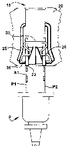
[0022] Figures 1-6 illustrate an exemplary embodiment of a lockout device 10
3
CA 02663430 2009-03-13
WO 2008/033397 PCT/US2007/019814
for a 110 volt AC electrical plug. As shown in Figures 1 and 2, the device 10
includes a body 20 with slots 22 in a first end sized to receive prongs P1, P2
of a
standard 110 volt AC electrical plug (see Figures 3A-3C). When the prongs P1,
P2
of the plug P are secured in the body 20, the plug P is prevented from being
coupled to a source of electrical power, such as a wall outlet. In another
embodiment (not shown), a lockout device could include only one slot to
lockably
retain only one of a plug's prongs, which may also effectively prevent use of
the
plug and its associated electrical device.
[0023] Many different types of retaining members may be utilized for many
different ways of retaining a connector within a body. In one embodiment, a
retaining member may include a prong retaining portion configured to extend
through a transverse aperture in one or more prongs of an electrical plug (as
conventionally provided with a 110 volt AC plug) when the retaining member is
moved from a releasing position to a retaining position. As the retaining
member
moves from the retaining position back to the releasing position, the prong
retaining portion withdraws from the transverse aperture or apertures to allow
the
electrical plug to be removed from the body. As shown in Figures 2 and 3A-3C,
the exemplary device 10 includes a retaining member 30 disposed within the
body
20. The exemplary retaining member 30, as more clearly shown in Figures 4A and
4B, is a single piece spring wire that includes at each end hooks or prong
retaining
portions 35 configured to extend laterally across the slots 22 and through the
prong
apertures Al, A2 when the retaining member 30 is moved to a prong retaining
position by insertion of the prongs P1, P2 (see Figure 3C).
[0024] Many different configurations may be used to axially move a retaining
member in response to insertion of an electrical plug into the body of a
lockout
device. In one embodiment, prong engaging portions extend across the slots,
such
that the ends of the prongs abut the prong engaging portions to axially push
the
retaining member from the releasing position to the retaining position during
plug
insertion. In the illustrated embodiment, laterally inward bends of the spring
wire
retaining member 30 form prong engaging portions 37 or "push feet," which are
axially pushed by the ends of the plug prongs P 1, P2 during plug insertion
(see
Figure 3B).
[0025] Many mechanisms may be utilized to direct the prong retaining portions
35 across the slots 22 and through the prong apertures Al, A2 as a result of
axial
4
CA 02663430 2009-03-13
WO 2008/033397 PCT/US2007/019814
movement of the retaining member 30. In one embodiment, a body includes guide
surfaces or walls positioned to direct one or more prong retaining portions
across
slots in the body for insertion through transverse apertures in one or more
prongs.
In the exemplary embodiment, as illustrated in Figures 3A-3C, the body 20
includes axially extending retaining guide walls 25 configured to squeeze
retaining
portions 35 of spring wire retaining member 30 inward as the prongs P1, P2 are
inserted into the body 20. As shown, the guide walls 25 may be angled inward
to
gradually squeeze or extend the retaining portions 35 during plug insertion,
which
may facilitate alignment with the prong apertures Al, A2, and ease of plug
insertion.
[0026] The retaining member 30 may be resiliently biased outward, such that
as the retaining member 30 is axially pulled from the prong retaining
position, the
prong retaining portions 35 are permitted to spring outward to retract out of
the
slots 22 and withdraw from the prong apertures Al, A2 (see Figure 3A).
Additionally or alternatively, the body 20 may include axially extending
releasing
guide walls 26, which may engage laterally inner surfaces of the retaining
member
30 to push retaining portions 35 outward and withdraw them from the prong
apertures Al, A2.
[0027] In another embodiment (not shown), retaining guide walls may be
disposed laterally inward of an inwardly biased retaining member, such that
axial
movement of the retaining member forces outward facing hooks or retaining
portions outward through prong apertures. As the retaining member is axially
pulled from the prong retaining position, the prong retaining portions are
permitted
to spring inward to retract out of the slots and withdraw from the prong
apertures.
Additionally or alternatively, the body may include axially extending
releasing
guide walls laterally outward of the retaining member, which may engage
laterally
outer surfaces of the retaining member to push retaining portions inward and
withdraw them from the prong apertures.
[0028] Many different mechanisms may be used to lock or secure a retaining
member of a lockout device in a connector retaining position, including, for
example, locking key cylinders, combination lock arrangements, and other such
mechanisms. In one embodiment, a lock opening may be provided with the
lockout device, the lock opening being positioned or configured to accept a
locking
member, such as, for example, a cable or the shackle of a padlock. When a
locking
CA 02663430 2009-03-13
WO 2008/033397 PCT/US2007/019814
member is secured in the lock opening, movement of the retaining member from
the retaining position to the releasing position is prevented. In one example,
shown in Figure 7, a lockout device 10' includes a lock opening 29' positioned
in
front and rear walls of the body 20' such that insertion of a lock member (not
shown) through the opening 29' would prevent movement of the retaining member
30 back to the prong releasing position.
[0029] In the illustrated embodiment of Figures 1-6, as most clearly shown in
Figures 2, 5A, and 5B, a plunger 40 is assembled with the retaining member 30
for
mutual axial movement of the plunger 40 and retaining member 30. When the
retaining member 30 is axially moved from the prong releasing position to the
prong retaining position, the plunger 40 extends through an opening 29 in a
second
end of the body 20 to expose a lock opening 49 of the plunger 40. When a
locking
member is secured in the lock opening 49 of the plunger 40, axial movement of
the
plunger 40 and retaining member 30 is prevented, and the retaining member is
held
in the prong retaining position. While many different configurations may be
used
to connect the plunger 40 with the retaining member 30, in the illustrated
embodiment, the plunger 40 includes a grooved portion 46 sized to receive a
loop
portion 36 of the retaining member 30.
[0030] In another embodiment, as shown in Figure 8A, a lockout device 110
includes a plastic (for example, molded nylon) retainer clip 130 including
prong
retaining portions 135 and prong engaging portions 137. Angled guide walls 125
force the retaining portions 135 inward into a prong retaining position when
the
prongs P1, P2 are inserted into the slots 122 and pressed against the prong
engaging portions 137. Axial movement of the retainer clip 130 and connected
plunger 140 exposes a lock opening 149, allowing it to receive a locking
member
(not shown) for securing the retainer clip 130 in the prong retaining
position. As
shown, the device 110 may, but need not, include a spring 150 disposed between
an inner surface of the body 120 and an outer surface of the plunger 140 to
bias the
retainer clip 130 back to the prong releasing position. As more clearly shown
in
Figures 8B and 8C, the retainer clip 130 may include a slot 136 for connecting
with a grooved portion 146 (Figure 8A) of the plunger 140.
[0031] While many different materials may be used to form the body and
plunger, in one embodiment, the body and plunger may be made from a non-
conductive, insulating material, such as a polymer, to provide a dielectric
lockout
6
CA 02663430 2009-03-13
WO 2008/033397 PCT/US2007/019814
device which insulates the electrical cord plug from being accidentally
energized.
The body may be produced from two body halves joined, for example, by
adhesives, fasteners, or welding. In one embodiment, the body may be produced
from two body halves that are substantially identical, which may facilitate
improved efficiencies in manufacturing, inventory storage, and assembly. In
the
illustrated embodiment, as shown in Figures 6A and 6B, the body 20 is formed
from two identical body halves 20a. Each body half 20a includes an outer
retaining guide wall 25 and a slot 27 for aligning with and receiving the
retaining
guide wall 25 of the other body half. Further, each body half 20a includes an
inner
wedge shaped releasing guide wall 26 and a recess 28 for aligning with and
receiving the releasing guide wall 26 of the other body half. The body halves
20a
may further be provided with complementary bead 21 and groove 23 weld
features,
to facilitate with ultrasonic welding of the polymer body halves 20a.
Additionally
or alternatively, the body halves 20a may be provided with complementary
shaped
pins 28a and bores 28b, for example, to facilitate alignment of the body
halves 20a
or to provide a snap-fit assembly of the body 20.
[00321 Other features may be provided with the lockout device 10. For
example, as shown in Figure 1, gripping surfaces 24 may be provided in the
sides
of the body 20 to intuitively guide the user to hold the device in the most
practical
position when using the device, also providing a gripping surface to hold onto
when removing the plug from the device. Similar gripping surfaces 44 may be
provided on the plunger 40 (see Figures 5A and 5B). Flat, recessed surfaces
may
be provided on the front and back sides of the body 20 to facilitate adhesion
of
rewritable or permanent labels (see Figure 1).
[00331 While various inventive aspects, concepts and features of the
inventions
may be described and illustrated herein as embodied in combination in the
exemplary embodiments, these various aspects, concepts and features may be
used
in many alternative embodiments, either individually or in various
combinations
and sub-combinations thereof. Unless expressly excluded herein all such
combinations and sub-combinations are intended to be within the scope of the
present inventions. Still further, while various alternative embodiments as to
the
various aspects, concepts and features of the inventions--such as alternative
materials, structures, configurations, methods, circuits, devices and
components,
software, hardware, control logic, alternatives as to form, fit and function,
and so
7
CA 02663430 2009-03-13
WO 2008/033397 PCT/US2007/019814
on--may be described herein, such descriptions are not intended to be a
complete
or exhaustive list of available alternative embodiments, whether presently
known
or later developed. Those skilled in the art may readily adopt one or more of
the
inventive aspects, concepts or features into additional embodiments and uses
within the scope of the present inventions even if such embodiments are not
expressly disclosed herein. Additionally, even though some features, concepts
or
aspects of the inventions may be described herein as being a preferred
arrangement
or method, such description is not intended to suggest that such feature is
required
or necessary unless expressly so stated. Still further, exemplary or
representative
values and ranges may be included to assist in understanding the present
disclosure; however, such values and ranges are not to be construed in a
limiting
sense and are intended to be critical values or ranges only if so expressly
stated.
Moreover, while various aspects, features and concepts may be expressly
identified
herein as being inventive or forming part of an invention, such identification
is not
intended to be exclusive, but rather there may be inventive aspects, concepts
and
features that are fully described herein without being expressly identified as
such
or as part of a specific invention. Descriptions of exemplary methods or
processes
are not limited to inclusion of all steps as being required in all cases, nor
is the
order that the steps are presented to be construed as required or necessary
unless
expressly so stated.
8