Note: Descriptions are shown in the official language in which they were submitted.
CA 02663631 2009-03-16
WO 2007/031743 PCT/GB2006/003387
WHEEL RIM COVER
Field of the Invention
The invention relates to wheel rim covers and kits of wheel rim covers.
Background to the Invention and Prior Art Known to the Applicant
2o Automatic tyre changing machines so called "tyre changers" are often used
to remove
tyres from alloy rims. Many such devices exist in the market place such as
those sold
under the brands Ravaglioli and Oma. These essentially have a rotatable table
onto which
the wheel as a tyre and alloy rim combination is placed and secured in
position. An arm
is then lowered with a D-shaped head onto the edge of the rim and the tyre and
rim are
rotated whilst the head causes the outer ply to be separated from the alloy
rim edge. The
head enters into contact with the edge of the rim. Tyre fitters who change a
large number
of tyres per day submit the apparatus to rigorous use whereby the heads become
worn and
tend to occasionally and if the head is not replaced which is often the case,
frequent alloy
rim damage occurs which is not desirable in the eyes of the customer. The only
way to
3o remove the scratches is then often to submit the alloy rim to a form of re-
coating or other
repair routine which will then cause the treated rim to stand out when
compared with the
set of other vehicle wheels of a particular user. The re-coating of alloys or
the repair of
CA 02663631 2009-03-16
WO 2007/031743 PCT/GB2006/003387
2
alloys ainounts to considerable costs as well as generating badwill for those
responsible of
fitting tyres. In practice, the vehicle will have to be fitted with spare
wheels whilst the
alloy repair takes place. In order to reduce the risk of scratching the
automatic tyre
changers' manufacturers recommend frequent replacements of the heads or at
least
replacing the rubber pads which are sometimes used on the D shaped heads.
With the increasing number of alloy wheels available, an immediately
deployable system
without requiring the replacement of these conventional tyre changers is
required.
1 o Summary of the Invention
In its broadest independent aspect, the invention provides a wheel rim cover
comprising:
an arc shaped member sized and shaped to fit at least over a portion of the
outer rim edge,
the cover extending at least from the edge over an outermost portion of the
rim which, in
use, is exposed; and the cover further comprises a bend around the edge to
secure the
cover onto the rim edge.
This combination of features is particularly advantageous because it protects
the edge of
the rim from scratching during the operation of removing the tyre from the
rim. It also
2o does not interfere with the removal of the tyre so that conventional
automatic tyre
changers may be used. This cover may also be used for the manual removal of
tyres from
the rim, if necessary, as it will offer improved protection of the outer rim.
It will avoid
having to recoat rims which are damaged during the conventional tyre removal
process.
In a subsidiary aspect in accordance with the invention's broadest independent
aspect, the
wheel rim cover further comprises clamping means to clamp the cover onto the
rim. In
this configuration, the wheel rim cover can be prevented from rotating about
the rim
which could otherwise cause undue wear and tear to the cover itself as well as
to the
protected rim.
In a further subsidiary aspect, the arc forms a circle where the circle has a
gap between
two circle end pieces and the cover incorporates a mechanism for immobilising
the two
end pieces relative to one another, thereby clamping the cover onto the rim.
This method
CA 02663631 2009-03-16
WO 2007/031743 PCT/GB2006/003387
3
of clamping is particularly advantageous because it removes any requirement
for
clamping to, for example, external surfaces such as the tyre changing
machinery or the
wheel itself.
In a further subsidiary aspect, the inner surface of the cover is a layer with
low abrasion
properties compared to conventional steel. This configuration will provide the
inner
surface with sufficiently low abrasion to avoid any scratching of the edge
whilst the cover
is in place.
io In a further subsidiary aspect, the inner surface of the cover has
relatively high friction
properties and the outside of the cover has relatively low friction
properties. This may,
for example, be achieved by employing rubber in the inside surface and steel
on the
outside surface so that the removing head of a tyre changer may be freely
displaced
against the cover on the outside whilst the cover itself is immobilised due to
the high
friction of an inside layer against the rim edge.
In a further subsidiary aspect, the invention provides a kit of wheel rim
covers according
to any of the preceding aspects.
2o The provision of a kit will allow a particular fitter to employ a range of
covers to
correspond with a range of rim sizes.
In a further subsidiary aspect, the covers are of varying sizes and are colour-
coded
according to their sizes. This will allow the tyre fitter to immediately find
which wheel
cover to employ for a given rim. These features will be particularly
beneficial when
considering that in the field of wheel fitters any improvement to the rapidity
of a fitter
being able to find the appropriate tool will allow greater efficiencies to be
achieved.
In a further subsidiaiy aspect, end portions of the arc are drawn together by
a mechanism
which is supported on two plates located within the arc and separated by a
gap.
In a further subsidiary aspect, both the arc and the plates incorporate inner
surfaces with
low abrasion properties.
CA 02663631 2009-03-16
WO 2007/031743 PCT/GB2006/003387
4
In a further subsidiary aspect, a tongue located on one of the plates
cooperates with a loop
located on the other plate in order to align the end portions of the arc.
Brief Description of the Figures
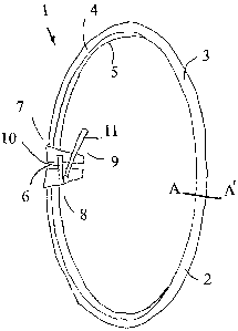
Figure 1 shows a wheel rim cover in perspective view.
Figure 2 shows a cross-sectional view along line AA'.
Figure 3 shows an alternative einbodiment of the invention using a 3/4 arc.
The figure
shows a plan view of the embodiment.
Figure 4 shows a further embodiment of the invention with a cover in plan view
Detailed Description of the Figures
Figure 1 shows a wheel rim cover generally referenced 1 with an arc shaped
member in
the form of a circle 2. The cover has an approximate C-shaped cross section.
The ring or,
circle shaped member incorporates a peripherally extending bend 3 with an
upper portion
4 and a lower portion 5 on either side of the bend. The upper portion 4 is
such that it
covers an outer most portion of the rim when the cover is placed on the rim.
The lower
portion 5 is such that it protects the outer edge of the rim as well as the
immediate
underneath of the outer edge. This configuration also effectively allows the
cover to be
snugly fitted onto the edge.
The cover may be made of steel or any other appropriately hard material. On
the inside of
the cover, between upper and lower portions 4 and 5, a layer of low abrasion
and high
friction material may be provided such as a layer of rubber-like material so
that the cover
grips the edge of the rim without the cover tending to rotate about the rim
edge.
CA 02663631 2009-03-16
WO 2007/031743 PCT/GB2006/003387
A gap 6 is provided between end extremities 7 and 8 of the cover allowing the
cover to be
adjusted for fine variations in rim diameter. Gap 6 also provides the cover
with sufficient
resilience so as to be more readily fitted onto the rim edge. In addition a
closing member
9 may be provided to clamp the cover onto the rim once the cover is placed
into position.
5 The closing mechanism may be selected from known alternatives by the person
skilled in
the art. The configuration presented incorporates a bar 10 for limiting the
amount by
which the gap 6 may be opened. A lever 11 may be secured against extremity 9
so as to
prevent the rim cover loosening during use.
lo Figure 2 shows cover, portion 12 with a bend 13 and an upper portion 14 and
a lower
portion 15. The upper portion 14 is of greater length than the lower portion
15 in order to
cover a greater outer most portion of the rim. The inside of the cover is
provided with a
rubber-like layer 16.
The invention also envisages the use of an entirely resilient rim cover so
that the cover
may be sized and shaped to allow a stretch fit onto the edge of a rim. Any
appropriate
elastic material may be selected from known alternatives by the person skilled
in the art.
Figure 3 shows a cover with an arc covering only 3/4 of the periphery of the
edge of the
2o rim. Arms 17 and 18 located at arc extremities 19 and 20 incorporate end
clamps 21 and
22 for securing the cover onto a neighbouring support structure. Whilst the
arm 17 is
shown as extending radially outwards, the invention also envisages the ann
extending
radially inwards so as to be attached to the wheel rim with a fitting which
will avoid any
abrasion of the rim occurring.
The above wheel covers may be packaged and iused as a kit of for example ten
ring-
shaped covers ranging from 13 inches to 22 inches to accommodate wide
variations in rim
sizes.
Once the rim cover is in place a conventional head of an automatic tyre
changing inachine
may be employed to run against the cover as it removes the tyre from the rim.
It is
understood that the cover is of the kind which is tough enough to resist the
force of a
conventional head of an automatic tyre changing machine running against the
cover
CA 02663631 2009-03-16
WO 2007/031743 PCT/GB2006/003387
6
without the head perforating the cover. The cover may receive surface damage
during use
whilst fulfilling its protective duty instead of the alloy wheel but the outer
surface of the
cover may be of relatively low friction to reduce wear and tear so that the
wheel cover
may be used for several tyre removal operations.
Figure 4 shows a further embodiment of the invention where the cover 24 has a
single
opening 25 in its ring. In cross-section the ring is C-shaped as shown in
cross-sectional
view 34. Plates 26 and 27 project from an upper portion 35 of the cover. These
are L-
shaped in plan view with optional cut-out portions 28 and 29 between the
plates and the
io cover's outer portion. A tongue 30 is attached or part of plate 27 and
projects across gap
25 in order to insert into loop 31 which acts as a guide for tongue 30. The
plates 26 and 27
may be drawn together and secured tightly on a wheel rim by locating the edge
of the rim
into receiving portion 36 and tightening spring loaded latch which uses a
spring 33 to
resiliently shut the latch and draw the plates together. Both the inside of
the ring and the
underside of the plates may be covered with low abrasive material with high
frictional
properties relative to the surface of an alloy wheel.
25
CA 02663631 2009-03-16
WO 2007/031743 PCT/GB2006/003387
7
CLAIMS
1. A wheel rim cover comprising: an are shaped member sized and shaped to fit
at least
over a portion of the outer rim edge, the cover extending at least from the
edge over an
outer inost portion of the rim which, in use, is exposed; and the cover
further comprises a
bend around the edge to secure the cover onto the rim edge.
2. A wheel rim cover according to the preceding claim further comprising
clamping
io means to clamp the cover onto the rim.
3. A wheel rim cover according to claim 2, wherein the circle has a gap
between two
circle end pieces and the cover incorporates a mechanism for immobilising the
two end
pieces relative to one another, thereby clamping the cover onto the rim.
4. A wheel rim cover according to any of the preceding claims, wherein the
inner surface
of the cover is a layer with low abrasion properties compared to conventional
steel.
5. A wheel rim cover according to any of the preceding claims, wherein the
inner surface
of the cover has relatively high friction properties and the outside of the
cover has
relatively low friction properties.
6. A wheel rim cover according to any of the preceding claims, wherein end
portions of
the arc are drawn together by a mechanism which is supported on two plates
located
within the arc and separated by a gap.
7. A wheel rim cover according to claim 6, wherein both the arc and the plates
incorporate
inner surfaces with low abrasion properties.
8. A wheel rim cover according to either of the preceding claims, wlierein a
tongue
located on one of the plates cooperates with a loop located on the other plate
in order to
align the end portions of the arc.