Note: Descriptions are shown in the official language in which they were submitted.
CA 02664470 2009-03-24
WO 2008/040542 PCT/EP2007/008616
CLOSURE APPARATUS FOR A PRESSURE CONTAINER, WHICH CAN
BE FILLED WITH COMPRESSED GAS, OF A COLD GAS GENERATOR
The invention relates to a closure apparatus for a
pressure container, which can be filled with compressed
gas, of a cold gas generator as claimed in the pre-
characterizing part of claim 1.
US patent specification 6,068,288 discloses a closure
apparatus for a pressure container, which can be filled
with compressed gas, of a cold gas generator. Cold gas
t generators of this type are used for vehicle air bag
systems. The closure apparatus comprises a valve body
which, in a rest position, closes a container opening
communicating with the environment. An electromagnetic
drive apparatus, by way of which the valve body can be
transferred into a working position, is provided for
outflow of the compressed gas. The closure body is
embodied as a slide. A movement of displacement can
release different flow paths to allow outflow of the
compressed gas. Furthermore, the movement of
displacement of the slide also causes the closure
apparatus to be reclosed. This apparatus has the
drawback that high forces are required for activating
the slide. In addition, these elevated forces impede
the activation of a slide of this type, above all the
closing movement of the closure device. This is often
associated with incomplete tightness, so that a leakage
flow is provided and the cold gas generator can be used
only to a limited extent or no longer at all for
further applications.
The invention is therefore based on the object of
providing a closure apparatus for a pressure container,
which can be filled with compressed gas, of a cold gas
generator and allows metered emission of the compressed
gas, which is under high pressure, and secure closing
after the emission of the compressed gas.
CA 02664470 2009-03-24
WO 2008/040542 PCT/EP2007/008616
- 2 -
According to the invention, this object is achieved by
the features of the main claim. Further advantageous
configurations and developments are disclosed in
further claims.
According to the invention, the closure apparatus has,
between the valve seat of an ejection opening and the
drive apparatus for actuating at least one valve body,
a device which is to be applied to the valve body,
which reduces the closing force and activates the valve
body between a working position and a rest position. As
a xesult of the reduction in closing force, a metered
and exactly controllable emission of the compressed
gas, which. is under high pressure and is to be emitted,
from the pressure container is facilitated. At the same
time, the force for opening the closure apparatus can
also be reduced. In a pressure container of this type,
the compressed gas will be present at an operating
pressure of from, for example, 600 to 1,000 bar. The
opening and closing movement of the closure apparatus
must take place within a few milliseconds and work
against these high operating pressures. Both abrupt
opening of the closure device and rapid blocking of the
container opening can be facilitated by a device
reducing the closing force to be applied to the valve
body. The electrical activation of the closure
apparatus allows the amount of compressed gas required
for an air bag to be adapted as a function of the
severity of an accident, such as for example the impact
speed. Furthermore, the filling speed and also
refilling of a pressure bag can be facilitated in the
event of a secondary impact.
According to a preferred embodiment of the invention,
provision is made for the device to have a pressure
element having at an end pointing toward the valve body
at least one pressure surface, by which at least one
CA 02664470 2009-03-24
wo 2008/040542 PCT/EP2007/008616
- 3 -
valve body can be transferred for abutment against an
opening of a valve seat. This allows the generation,
via the pressure surface which is embodied in
particular in a conical manner, of leverage forces
which reduce the closing force which is actually
required. At the same time, a low release force is also
facilitated, thus allowing simple activation via an
electric drive.
According to a preferred embodiment, there are provided
on a valve insert a plurality of radially oriented
~i openings with each of which a valve body is associated.
The preferably conical pressure surface of the pressure
element acts preferably jointly on the valve bodies.
The valve bodies can for example be embodied as sealing
balls or sealing segments which are arranged relative
to one another in the circumferential direction by a
cage. As a result of the conical surface on the
pressure element, all valve bodies can preferably be
acted on uniformly and simultaneously, so that a rapid
closing movement is also facilitated. Alternatively, a
successive closing movement of individual valve bodies
can also be provided.
Furthermore, provision is preferably made for the
pressure element to be able to be activated by the
drive apparatus so as to be displaceable to at least
one valve body and the pressure surface on the pressure
element to be embodied at an acute angle to the
direction of displacement. As a result, a very high
contact force can be brought about in order to position
the valve bodies for opening on the valve insert in the
direction of radial movement and to close the
respective opening. The stroke distance and the
inclination of the conical surface can be adapted to
the shape of the valve bodies and the required opening
cross section. The pressure surface can also have a
curved or hyperbolic course.
CA 02664470 2009-03-24
WO 2008/040542 PCT/EP2007/008616
- 4 -
The pressure element and the valve insert form
preferably a receiving space for the valve bodies,
which is delimited by a radially oriented abutment
surface. This abutment surface directly adjoins a
radial opening on the valve insert. As a result, the
valve bodies, in particular the sealing balls, remain
in this receiving space. At the same time, this
abutment surface acts as a counter bearing during the
closing movement of the pressure element in order to
move the valve bodies toward the opening in the valve
~ insert via the slant.
According to this first advantageous embodiment, the
pressure element comprises a cup-shaped portion which
surrounds the at least one valve body. In this case,
the cup-shaped portion receives at an internal free end
the pressure surface, in particular a conical surface,
and through-openings are provided between the base and
the pressure surface on the cup-shaped portion. Thus,
there can take place not only an outflow between the
valve bodies, but rather an additional outflow of the
compressed gas via the through-opening, thus
t facilitating a rapid supply of the compressed gas in a
pressure bag or air bag.
The pressure element has furthermore in the cup-shaped
portion a guide acting on the outer circumference of
the valve insert. As a result, the pressure element is
guided in direct proximity to the valve bodies, thus
facilitating exact guidance of the conical surfaces for
positioning the valve bodies relative to the openings
in the valve insert.
Preferably, a force storage element, in particular a
compression spring which exerts a force on the pressure
element in the closing direction of the valve bodies,
is provided between the drive apparatus and the
CA 02664470 2009-03-24
WO 2008/040542 PCT/EP2007/008616
- 5 -
pressure element. As a result, it is possible, owing to
the compression spring, for the closure apparatus to be
transferred into and held in a rest position in a
currentless state. This currentless rest position is
required as a safety measure, so that there is no
accidental outflow of the compressed gas in the event
of failure of a control current. As a result of the
device according to the invention for reducing the
closing force, a compression spring having reduced
compressive force can be provided, thus facilitating a
reduction in overall space.
The force storage element is preferably provided in a
chamber in the housing of the drive apparatus, which is
embodied so as to be open toward the valve body and has
lateral through-openings. As a result, a compact design
can be attained in that the housing is fixed to the
connecting edge of a cover of the pressure container
and a flow path for the compressed gas from the
pressure container to the air bag is released to allow
rapid filling.
According to a preferred embodiment, the valve insert
~ is fastened in an ejection opening in the cover for the
pressure container. This cover can be a part of the
closure apparatus or, already as a component, be
securely pressed onto or connected to the pressure
container. The valve insert is arranged in a central
ejection opening in the cover, preferably so as to be
releasable by a screw thread.
The drive apparatus has preferably a fastening portion
which acts on a connecting edge of the cover, so that
the drive apparatus can be mounted to the pressure
container. Thus, the pressure container can also be
provided separately to the closure apparatus and allows
simple mounting and subsequent filling.
CA 02664470 2009-03-24
WO 2008/040542 PCT/EP2007/008616
- 6 -
Furthermore, an excess pressure limiting valve, which
can be inserted in a hole connecting the ejection
opening to the environment, is preferably provided in
the cover. As a result, a maximum high pressure for the
container interior can be set.
Furthermore, provision is preferably made for the cover
to have on the connecting edge a further fastening
portion on which the bag or air bag, which can be
filled with compressed gas, is arranged. This allows
simple mounting. This fastening portion can be
standardized, so that various embodiments of compressed
gas bags can be fastened thereto.
A second preferred embodiment of the invention provides
for a device which reduces the closing force to be
applied to have a valve body which is embodied as a
piston, abuts with an end face against a valve seat on
the ejection opening and comprises a first pressure
surface and for the valve body to be arranged opposite
in a prechamber in which a restrictor valve can be used
to set a prechamber pressure which is reduced compared
to the operating pressure of the compressed gas and
acts on a second pressure surface of the valve body in
the prechamber. As a result of this configuration, a
reduction of the closing forces is attained owing to a
pressure compensation of the at least two pressure
surfaces. Facilitated closing can be attained as a
result.
For adjusting the prechamber pressure according to the
second embodiment, the restrictor valve is provided in
a channel connecting the prechamber to the pressure
container. This provides a simple design in order to
build up in the prechamber a pressure which can
preferably be adjusted by the restrictor valve.
CA 02664470 2009-03-24
WO 2008/040542 PCT/EP2007/008616
- 7 -
Furthermore, provision is preferably made for the
piston to be held by a holding sleeve which can be
arranged on the drive apparatus and for the holding
sleeve to comprise a guide portion. As a result, the
pressure element can be guided in a tilt-free manner.
The holding sleeve can be embodied as a separate
component or be integrated in one piece with the cover.
In order to reduce the forces by a pressure
compensation in the device, provision is furthermore
made for the valve body to have, between the first
t^ valve seat and a further valve seat formed by the
holding sleeve, a third pressure surface to which
atmospheric pressure is applied. This third pressure
surface is preferably annular in its embodiment.
Furthermore, this facilitates a reduction in force, as
the forces from the pressure of the prechamber and the
annular cross section of the third pressure surface and
also of the first pressure surface add up. If the cross
sections and the pressure difference are selected in a
suitable manner, the resulting force can even be equal
to zero.
Advantageously, sealing elements are provided between
the holding sleeve and the housing of the drive
apparatus and preferably between the guide portion of
the holding sleeve and the valve body. As a result,
stable prechamber pressures are maintained. At an
operating pressure of the compressed gas in the
pressure container of for example 800 bar, a prechamber
pressure of for example 400 bar is preferably set via
the restrictor valve.
According to a further advantageous configuration of
the invention, a force storage element, in particular a
compression spring which exerts a force in the closing
direction, is provided in the prechamber. As a result
of the pressure compensation attained via the pressure
CA 02664470 2009-03-24
WO 2008/040542 PCT/EP2007/008616
- 8 -
surfaces, a force storage element having a low force
can be used to apply the necessary sealing pressure or
the required sealing force, so that the closure
apparatus securely closes the pressure container in the
currentless state. At the same time, simple activation
is facilitated, preferably via an electromagnet which
works against the spring force during opening of the
closure apparatus.
According to a preferred third alternative embodiment
of the invention, provision is made for an opening
~ movement of the valve body for opening the ejection
opening in the cover not to be activated directly by
the drive apparatus, but rather to be able to be
activated via the prechamber pressure prevailing in the
prechamber. For this purpose, provision is preferably
made for the prechamber pressure to be able to be
varied by a control valve which opens and closes a
through-opening between the prechamber and a transverse
hole to which atmospheric pressure is applied. The
valve body is provided in the prechamber so as to be
able to move freely. Owing to the pressure compensation
between the container internal pressure and the
prechamber pressure and also the conditions of the
pressure surfaces, the piston remains in a closed
position when the control valve is closed. As soon as
the control valve opens and the compressed gas flows
outward from the prechamber, the resulting excess
pressure of the compressed gas in the pressure
container will lift the valve body from the valve seat,
and the compressed gas can escape.
Preferably, provision is made for the control valve to
be able to be activated by the drive apparatus. As a
result, the valve body is activated directly via the
drive apparatus, i.e. the valve body is indirectly
activated in order to transfer the valve body into a
working position and to open the ejection opening.
CA 02664470 2009-03-24
WO 2008/040542 PCT/EP2007/008616
- 9 -
Preferably, a force storage element, which applies a
force to the control valve in the closing direction, is
in turn provided. This in turn provides the safety
function that the compressed gas container is kept
closed in the currentless state of the closure
apparatus.
According to a further advantageous configuration of
the third embodiment, provision is made for the control
valve to have a valve seat in an intermediate flange
{ which receives the drive apparatus and can be arranged
on the cover. This provides a modular construction,
individual components being provided so as to be able
to be exchanged in a simple manner. At the same time, a
seal can be provided at the individual interfaces, so
that the prechambers are in turn pressure-resistant.
According to a further alternative embodiment of the
invention, provision is made for, between a guide
portion of the valve body, which at least partly
surrounds the valve body of the control valve, and a
valve body of the control valve, a forced activation to
be provided in such a way that during an opening
movement of the valve body from the control valve, the
valve body is raised from the at least one valve seat
of the ejection opening. This forced control in a
direction of movement allows very high gas volumes to
be controlled at high pressures without particularly
high forces having to be applied for this purpose. At
the same time, opening is ensured.
The embodiments having a prechamber all have the
advantage that simple filling of the pressure
containers is facilitated without what is known as a
bell, such as is required in pyrotechnically opened
hybrid or cold gas generators.
CA 02664470 2009-03-24
WO 2008/040542 PCT/EP2007/008616
- 10 -
Furthermore, this alternative embodiment has the
advantage that the drive apparatus for activating the
control valve can be designed as an electromagnetic
drive. Owing to the low forces and the low stroke
distance, piezoceramic plate stack drives or
piezoceramic bending plate drives can for example also
be provided.
According to a further preferred configuration of the
invention, provision is made for the activation of the
drive apparatus and/or the pressure containers to be
monitored by a pressure sensor. As a result, single or
multiple brief opening and closing of the valve can be
carried out. The outflowing volume can also be
determined by the activatable valve strokes. The use of
pressure sensors of this type allows a closed control
circuit, thus providing information about the amount of
gas which has flowed out. The pressure sensor also
allows the operativeness and the filling amount of the
gas generator to be constantly checked. This
facilitates maintenance in particular.
The invention and also further advantageous embodiments
and developments thereof will be described and
commented on in greater detail hereinafter based on the
examples illustrated in the drawings. According to the
invention, the features which may be inferred from the
description and the drawings can be applied
individually per se or jointly in any desired
combination. In the drawings:
figure 1 is a schematic sectional view of a cold gas
generator with a first embodiment according to the
invention of a closure apparatus;
figure 2 is an enlarged schematic sectional view of the
closure apparatus according to figure 1 in the closed
state;
CA 02664470 2009-03-24
WO 2008/040542 PCT/EP2007/008616
- 11 -
figure 3 is a schematically enlarged sectional view of
the closure apparatus according to figure 1 in the
opened state;
figure 4 is a schematic sectional view of an embodiment
of a closure apparatus as an alternative to figure 1;
figure 5 is a schematic sectional view of the closure
apparatus according to figure 4 in the opened state;
figure 6 is a schematic sectional view of a further
embodiment of a closure apparatus;
figures 7a and b are a schematic sectional view of a
further alternative embodiment of a closure apparatus
according to figure 1;
figure 8 is a schematic sectional view of an embodiment
of a closure apparatus as an alternative to figure 1;
figure 9 is a schematic sectional view of the closure
apparatus according to figure 8 in the opened state;
figure 10 is a schematic sectional view of an
embodiment of a closure apparatus as an alternative to
figure 1; and
figure 11 is a schematic sectional view of the closure
apparatus according to figure 10 in the opened state.
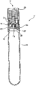
Figure 1 is a schematic sectional view of a cold gas
generator 11 with a first embodiment of a closure
apparatus 12 which is provided on a pressure container
14. The pressure container 14 has at the upper end a
container opening 16 which is closed by a cover 17.
Alternatively, this cover 17 can also be embodied in
one piece on the pressure container 14 or as a
CA 02664470 2009-03-24
WO 2008/040542 PCT/EP2007/008616
- 12 -
component of the closure apparatus 12. The cover 17
has, preferably centrally, an ejection opening 18 which
can be activated by the closure apparatus 12. The cover
17 comprises a connecting edge 19 to which the closure
apparatus 12 is releasably fastened. Furthermore, the
connecting edge 19 can have a fastening portion 21,
preferably a thread, to which a pressure bag 22 or an
air bag attachment or a filling device is fastened in a
medium-tight manner.
In this embodiment, provision is made for the closure
apparatus 12 to be arranged outside the pressure
container 14. Alternatively, the closure apparatus can
also be provided in the pressure container 14.
An excess pressure limiting valve 24, which opens if
the internal pressure rises above the admissible
bursting pressure of the pressure container 14 and
allows the compressed gas to be blown off, is provided
in the cover 17. Preferably, provision is made for the
excess pressure limiting valve 24 to comprise a
pressure sensor 27 which is likewise arranged in a hole
26 connecting the container interior to an atmospheric
pressure outside the pressure container 14. This
{ 25 pressure sensor 27 can be embodied as part of a
pressure plate to detect the pressure applied. As a
result, the filling amount of the compressed gas in the
pressure container 14 can be detected.
Figure 2 is an enlarged view of the closure apparatus
12 according to the invention. The closure apparatus 12
consists of a drive apparatus 31 which is preferably
embodied as an electromagnetic drive. This drive
apparatus 31 acts on a device 33 which reduces the
closing force and is provided between a valve seat 51
of an ejection opening 18 and the drive apparatus 31.
CA 02664470 2009-03-24
WO 2008/040542 PCT/EP2007/008616
- 13 -
The device 33, which reduces the closing force to be
applied, comprises a pressure element 41 which is
connected to an anchor 42 of the drive apparatus 31,
which can be moved via an actuator 43 or electromagnet.
The pressure element 41 has, at its end pointing toward
the ejection opening 18, a cup-shaped portion 46, on
the inside of which a preferably conical pressure
surface 47 is provided. This conical surface 47 acts on
at least one valve body 48 which is embodied for
example as a pressure or sealing ball. This valve body
48 closes at least one opening 49 on a valve inside 50
which can be inserted into the ejection opening 18. The
valve insert 50 has preferably a plurality of radially
oriented openings 49 which are connected to an entry
region 52 which merges with the ejection opening 18.
Provided adjoining the opening 49 of the valve insert
50 is an abutment surface 54 which delimits a receiving
space 56 formed between the valve insert 50 and the
inner circumference of the cup-shaped portion 46 of the
pressure element 41. The abutment surface 54 is
embodied as an annular surface which can dip at least
partly into the cup-shaped portion 46. The valve bodies
48 rest on the abutment surface 54.
The opening and closing movement of the pressure
element 41 takes place along a longitudinal axis 58
which is preferably congruent with the axis of the
ejection opening 18. The pressure element 41 can move
upward against a force storage element 59 which is
preferably embodied as a compression spring. The force
storage element 59 is provided in a chamber 61 which is
a part of a housing 62 of the drive apparatus 31 with
which this housing is fastened to the connecting edge
19. Radially oriented openings 63 are in turn provided
in the chamber 62 to allow the compressed gas to flow
out.
CA 02664470 2009-03-24
WO 2008/040542 PCT/EP2007/008616
- 14 -
The conical pressure surfaces 47 of the pressure
element 41 are adjoined by a cylindrical wall surface
66 in which through-holes 67 are provided, so that the
compressed gas entering the receiving space 56 can flow
outward. A guide 68, which acts on an outer
circumference of the valve insert 51, is provided on
the base of the cup-shaped portion 46.
Figure 2 shows the closure device 12 in a closed
position. In this case, the drive apparatus 31 is
currentless and the ejection opening 18 closed. The
closing force is applied via the force storage element
59, wherein, owing to the device 33, the closing force
of a force storage element 59, in particular a
compression spring, is sufficient. Owing to the conical
surface 47 or a control cam, the holding forces are
greatly reduced. This arrangement according to the
invention includes a gain factor corresponding to the
tangent of the angle of the conical pressure surface 47
relative to the longitudinal axis 58.
Figure 3 shows the closure apparatus according to
figure 2 in a working position. The ejection opening 18
~ is opened, so that the compressed gas can pass from the
pressure container 14 into the pressure bag 22 as
indicated by the arrows 69. For opening the ejection
opening 18, the actuator 43 of the drive apparatus 31
is supplied with current. The anchor 42 is drawn upward
and works against the force storage element 59, so that
the pressure element 41 is moved upward. In this case,
the contact pressure acting on the valve bodies 48 is
reduced by the conical surface 47 and, owing to the
increasing angle or free space, the valve bodies
release the openings 49 of the valve insert 50. The
compressed gas can enter the receiving space 56 and
from there pass via the transverse holes 67 to the
chamber 61 and through the openings 63 into the
pressure bag 22. For closing the closure apparatus, the
CA 02664470 2009-03-24
WO 2008/040542 PCT/EP2007/008616
- 15 -
drive apparatus 31 is switched to the currentless
state. The stored force of the compression spring 59
leads the pressure element 41 toward the valve body 51.
The valve bodies 51 are pressed toward the respective
openings 49 via the conical pressure surfaces 47, so
that the openings are closed.
Figure 4 shows an alternative embodiment of the closure
apparatus 12 according to figures 1 to 3 in a closed
position. Figure 5 shows this alternative embodiment
with an opened closure apparatus 12. This alternative
embodiment has a closing force-reducing device 33 which
differs from figures 1 to 3. This device 33 will be
described hereinafter in greater detail. Moreover,
reference is made to the foregoing description.
The device 33 comprises a valve body 71 having an end
face 72. Opposite, the valve body 71 comprises an
annular surface 73 which points into a prechamber 74.
The valve body 71 passes through the prechamber 74 with
a ram or plunger and is connected to the anchor 42 of
the drive apparatus 31. A force storage element 59,
which acts on the annular surface 73 and in the chamber
61 of the housing 62, is in turn arranged in the
prechamber 74. Furthermore, a holding sleeve 76, which
holds the piston 71 in the prechamber 74, is provided
on the housing 62. This holding sleeve 76 has a guide
78 which receives a circumferential wall portion of the
piston 71 in a longitudinally displaceable manner in
the prechamber 74. Preferably, the guide 78 can be
provided by seals 79.
A valve seat 51, which is for example molded in one
piece onto the cover 17, surrounds the ejection opening
18. The valve body 71 rests with the end face 72
against a first valve seat 51. The region of the end
face 72 that covers the ejection opening 18 forms a
first pressure surface 81. The internal pressure of the
CA 02664470 2009-03-24
WO 2008/040542 PCT/EP2007/008616
- 16 -
compressed gas acts on this pressure surface 81. A
channel 82, which leads to the prechamber 74, is
provided in the first pressure surface 81. A restrictor
valve 83, which can be constructed in a similar manner
to the excess pressure limiting valve 24, is provided
in the channel 82. Compressed gas passes from the
pressure container 14 into the prechamber 74 via the
channel 82 as a function of the preset pressure of the
restrictor valve 83. This compressed gas acts on the
annular surface 73 which acts at least partly as the
second pressure surface 84. An annular portion, to
{ which atmospheric pressure is applied, is formed on the
valve body 71 between the valve seat 51 and a valve
seat 77 of the holding sleeve 76. This annular surface
forms a third pressure surface 86.
The force-reducing device 33 is determined by the
extent of the pressure difference between the operating
pressure, the prechamber pressure of the compressed gas
and the atmospheric pressure. The extent of the
pressure difference thus forms the yardstick for the
force with which the valve body 71 must be pressed
against the valve seat 51. An example will illustrate
this most clearly: The operating pressure of the
compressed gas generates on the first pressure surface
81 a force which might raise the valve body 71. The
pressure of the prechamber 74 presses against the first
pressure surface 81 and also against the third pressure
surface 86 with the force of the second pressure
surface 84. As the third pressure surface 86 displays
ambient pressure, the force is intensified as a result
of the pressure of the prechamber 74 against the valve
body 71 and the valve seats 51, 77.
The restrictor valve 83 can now be adjusted in such a
way that the forces of the first to third pressure
surfaces 81, 84, 86 are compensated for. In such a
case, the force storage element 59 ensures the required
CA 02664470 2009-03-24
WO 2008/040542 PCT/EP2007/008616
- 17 -
sealing pressure and the actuator 43 has, during the
opening of the ejection opening 18, to overcome merely
the force of the force storage element 59. Preferably,
the restrictor valve 83 is adjusted in such a way that
the force acting on the valve body 71 on the prechamber
side is slightly higher than the force which the gas
pressure exerts on the end face 72 of the valve body
71. The force of the force storage element 59 and the
pressure ratio between the pressure of the prechamber
74 and the compressed gas and also the cross-sectional
ratios between the ejection opening 18 and the third
pressure surface 86 are adapted in such a way that a
sufficient reserve force is present for the drive
apparatus 31 in order if appropriate to compensate for
thermally induced pressure tolerances, so that the
closure apparatus 12 can always be securely opened.
Figure 6 shows a further embodiment of a closure
apparatus 12. With regard to points of correspondence
to the embodiment according to figures 4 and 5,
reference is made to the description concerning the
embodiment according to figures 4 and 5. In contrast
thereto, the holding sleeve 76 is for example molded in
~ one piece onto the cover 17. Transverse holes 85, which
allow during raising of the valve body 71 from the
valve seat 51 the compressed gas to flow out from the
outlet opening 18 into the pressure bag 22 via the
transverse hole 85, are provided in this holding sleeve
76.
A pressure channel B2, which completely penetrates the
valve body 71 and the anchor 42 which is preferably
molded thereon in one piece, is provided in the valve
body 71. Upstream of the pressure channel 82, a
restrictor 83 is embodied as a fixed restrictor which
acts during an opening movement. Owing to the passage
via the restrictor 83, the same pressure is applied in
the prechamber 74 as in the pressure container 16.
CA 02664470 2009-03-24
WO 2008/040542 PCT/EP2007/008616
- 18 -
Atmospheric pressure is applied in the pressure bag 22,
meaning that atmospheric pressure is applied via the
transverse holes 85 and an annular peripheral groove
87. The valve seat 51 seals the pressure volume in the
pressure container 16, the size or the width of the
valve seat 51 being determined by the arrangement of a
groove 87 in the cover 17 and an oblique surface 88 on
the valve body 71. The second valve seat 77 is embodied
as a sealing surface and seals the prechamber 74
against the atmospheric pressure. This seal or sealing
surface is provided as an alternative to the annular
seals on the guide 78 according to figures 4 and 5. In
addition, a sliding seal can be provided for guiding
the piston or the valve body 71 and also for sealing
the prechamber 74.
In order to attain sealing pressures which are as high
as possible for the closure device 12, the annular
surface of the valve body 71, which rests against the
valve seat 51, is kept as small as possible in relation
to the end face 81 of the outlet opening 18. This can
be assisted by the design measure via the groove 87 and
the oblique surface 88. The difference in the size of
the sealing surface on the valve seat 77 relative to
the outer circumference of the valve seat surface 51
should also be kept as small as possible. Preferably, a
phase or an oblique surface 88 is provided on the outer
circumference of the valve seat 77 or the sealing
surface and also on the outer circumference of the
valve body 71, pointing in each case toward the valve
seat surface, in order to reduce the size of the
surface of the valve seat 77. This configuration or
geometrical design of the closure apparatus 12 allows
the piston 71, which seals the pressure space in the
pressure container 14 against the environment via
sealing seats, to float in compressed gas and thus to
be free from compressive forces. The sealing force is
applied exclusively or almost exclusively by the
CA 02664470 2009-03-24
WO 2008/040542 PCT/EP2007/008616
- 19 -
compression spring 59. Good adaptation to the seals
used, which allow even long-term sealing, is thus
possible. Control becomes very effective and can be
carried out in an exact manner. For the outflow of the
compressed gas, the compressed gas requires merely a
slight deflection in order to flow into the pressure
bag 22 through the radially arranged transverse holes
85.
Additionally or alternatively, the sealing surface of
the valve seat 77 or an opposing installation can
~. comprise a ring seal 79. The same applies to the end
side 81 of the valve body 71 or the opposing abutment
surface which forms the valve seat 51. In this case,
the positioning of the seals 79, which are embodied in
particular as a seat seal, are adapted in diameter in
such a way that the prechamber pressure in the
prechamber 74 and the pressure, acting on the valve
body 71, of the force storage element 59 is greater
than the internal pressure in the pressure container 14
and the atmospheric pressure which both act on the
valve body 71. The closing force results therefrom.
Figures 7a and b show a further alternative embodiment
of the force-reducing device 33 for a closure apparatus
12. This embodiment is a modification of the embodiment
according to figure 6. With regard to the points of
correspondence, reference is made to the description
concerning figure 6. Figure 7a shows the closure
apparatus 12 in a closed position and figure 7b shows
it in an open or outflow position. The valve body 71
comprises a valve body 95 of a second control valve 93
which is embodied as a servo control valve or as a
force-reducing control valve for reducing the opening
forces. The valve body 95 of the control valve 93 is
provided in the valve body 71 in a longitudinally
movable manner. This valve body 95 is connected to the
anchor 42. Via a spring ring 97, the valve body 95 is
CA 02664470 2009-03-24
WO 2008/040542 PCT/EP2007/008616
- 20 -
secured relative to the valve body 71 and delimited
with regard to the opening movement thereof. The
internal pressure of the pressure container 16 enters
the channel 82 via the restrictor valve 83 and acts on
a conical surface of the valve body 95. The conical
surface of the valve body 95 closes a through-hole 92
through which the medium in the pressure container 14
can enter the pressure bag 22 via the transverse
channels 85 after the raising of the valve body 95.
The force storage elements 59 shown in figure 7a can
both be provided. Alternatively, it is also possible
for only one of the two force storage elements 59 to be
provided. Also shown in this embodiment is a sealing
sleeve 79 which separates the actuator 43 from the
high-pressure space with regard to the prevailing
pressures.
The closing force in this embodiment results from the
fact that there acts on the cross section of the
conical tip of the valve body 95 of the control valve
93, which closes the opening 92, a container internal
pressure and a closing force of the force storage
( element 59, which is opposed by an atmospheric pressure
which is determined by the cross-sectional area of the
hole diameter of the opening 92. Owing to the reduction
of the pressure areas acting on the diameter of the
opening 92, extremely low closing forces are required.
This allows an activation of the actuator 43 to cause
rapid opening of the control valve 73, so that the
pressure acting firstly in the prechamber 74 can flow
out to the environment or into the pressure bag 22.
Subsequently, the container internal pressure acts on
the first pressure surface 81 of the valve body 71 and
raises from the valve seat surface 51, so that the
medium can flow from the container interior into the
pressure bag 22 directly via the transverse channels
85. This position is shown in figure 7b.
CA 02664470 2009-03-24
WO 2008/040542 PCT/EP2007/008616
- 21 -
Figures 8 and 9 show a further alternative embodiment
of the force-reducing device 33 for a closure apparatus
12. In this embodiment, the holding sleeve 76 is for
example integrally connected to the cover 17. The valve
body 71 is provided in the prechamber 74 so as to be
able to move freely. The prechamber 74 is delimited by
an intermediate flange 91 which, opposite this,
receives the housing 62 of the drive apparatus 31 and
is fastened, in particular by a screw connection, to
the holding sleeve 76, a seal 79 preferably being
t interposed. The intermediate flange 91 comprises an
opening 92 connecting the prechamber 74 to the
environment via a transverse hole 94. This opening 92
can be activated by a valve body 95 of the control
valve 93.
The closing force-reducing device 33 comprises in turn
the components between the valve seat 51 of the
ejection opening 18 and the drive apparatus 31. The
drive apparatus 31 comprises an anchor 42 which can be
connected to the valve body 95 integrally or by a
releasable connection, the valve body being in turn a
component of the control valve 93 and a part of the
closing force-reducing device 33. The force storage
element 59 is in turn mounted by the drive apparatus in
a chamber 61 of the housing 62 and moves the valve body
95 into a closed position relative to the opening 92.
The following activation results from this arrangement.
As in the preceding embodiment, the valve body 71 is
pressed downward with ambient pressure by the pressure
of the prechamber 74 against the forces in the region
of the first pressure surface 81 and the force of the
third pressure surface 86. The pressure difference
between the compressed gas and the prechamber volume is
adjusted via the restrictor valve 83. In this
embodiment, the control valve 93, which operates merely
CA 02664470 2009-03-24
WO 2008/040542 PCT/EP2007/008616
- 22 -
against ambient pressure and the spring force of the
force storage element 59, is activated for opening the
valve body 71. As soon as the control valve 93 opens
the opening 92, the pressure prevailing in the
prechamber 74 can flow out to the environment, as a
result of which in the prechamber 74 the pressure
decreases and becomes less than that acting on the
first pressure surface 81. This causes opening of the
valve body 71, so that the compressed gas can flow out
of the interior of the pressure container 41, as is
illustrated in figure 7. The compressed gas flows out
of the pressure container 14 via the ejection opening
18, is deflected on the end face 72 and passes via an
annular space 80, a large number of holes or hole
segments into one or more transverse channels 85 which
guide the compressed gas into the interior of a
pressure bag 22.
The force storage element 59 is designed in such a way
as to provide a sufficient force which, in the
currentless state of the drive apparatus 31, closes the
control valve 93 and which is preferably greater than
the force resulting from the pressure of the prechamber
74 and the cross section, lying in the first pressure
t,
surface 82, of the channel 82. During closing of the
control valve 93, the restrictor valve 83 is opened
owing to the excess pressure, which is still present,
of the compressed gas, so that the pressure, which can
be preset by the restrictor valve 83, in the prechamber
74 is re-established. As a result, the valve body 71 is
moved downward and closes the ejection opening 18. In
this case, the end side 72 of the valve body 71 rests
against the first valve seat 51. At the same time, the
end face 72 abuts against the second valve seat 77
which is provided on the holding sleeve 76. This
causes, in turn, the ambient pressure to act on the
third pressure surface 86 and also the container
internal pressure to act on the first pressure surface
CA 02664470 2009-03-24
WO 2008/040542 PCT/EP2007/008616
- 23 -
81. The compressed gas can thus be emitted into the
pressure bag 22 in a metered manner by way of rapid,
successive opening and closing processes of the control
valve 93. This arrangement allows a gentle activation
with a short activation time to be attained.
Figure 10 shows a further embodiment of a closure
apparatus 12 as an alternative to figures 8 and 9 in a
closed position. Figure 11 shows the alternative
embodiment according to figure 10 in a working
position.
The closure apparatus 12 has been modified compared to
those in figures 8 and 9 in that a forced activation is
provided for the opening movement of the valve body 71.
For this purpose, the valve body 71 is preferably
embodied in two parts. The valve body 71 comprises a
lower or first region which has an end face 72 and
receives, opposite this, the opening 92. This opening
92 is displaced by the intermediate flange 91 into the
valve body 71. The intermediate flange 91 receives the
valve body 71 in a displaceable manner. As a result,
the entire control valve 93 is movable relative to the
~ intermediate flange 91. The opening 92 merges via a
connecting hole 98 with a transverse hole 94 provided
in the intermediate flange 91. The guide portion 96 is
fastened by a screw connection to the lower part of the
valve body 71 in order to allow simple mounting. The
valve body 95 of the control valve 93 is guided
substantially in the lower part of the piston in order
to open the opening 92 which is connected to the
prechamber 74 by channels 99. The valve body 95 has
additional guide portions 101 by which the valve body
can be guided in a wall portion in the guide portion
96. Furthermore, a spring ring 97 or the like, which
forms an undercut for the further guide portion 101 on
the valve body 95, is inserted in the guide portion 96.
The valve body 95 is in turn connected to the anchor 42
CA 02664470 2009-03-24
WO 2008/040542 PCT/EP2007/008616
- 24 -
of the drive apparatus 31, a force storage element 59
being provided in the chamber 61 of the housing 62 of
the drive apparatus 31 and transferring the valve body
95 of the control valve 93 into a closed position.
This device 33, which reduces the closing force,
functions firstly like that according to the embodiment
in figures 7 and 8. On activation of the control valve
93 for opening the opening 92, a free movement of the
valve body 95 of the control valve 93 first takes
place. Subsequently, the entire valve body 71 is
forcibly raised via the additional guide portion 101
which rests against or reaches behind the spring ring
97. As soon as the drive apparatus 31 is switched to
the currentless state or is switched off, the force
storage element 59 presses in turn the valve body 95
downward against the opening 92. As the prechamber
volume is substantially pressureless, the restrictor
valve 83 opens, and the set pressure difference between
the gas pressure in the pressure container 14 and the
prechamber pressure is re-established. The closing
movement of the valve body 71 is initiated and if
appropriate assisted by the force storage element 59
~ which presses the valve body 71 against the first and
second valve seat 51, 77.
The closure apparatuses 12 according to figures 8 to 11
thus have a pneumatic servo mechanism. The closure
apparatus 12 according to figures 1 to 3 has, on the
other hand, a mechanical servo mechanism. The device 33
thus reduces the actuating force for opening and/or
closing of the ejection opening by at least one valve
body.
All features described hereinbefore are each per se
essential to the invention and can be combined with one
another in any desired manner.