Note: Descriptions are shown in the official language in which they were submitted.
CA 02664574 2009-03-25
WO 2008/039516 PCT/US2007/020855
SPLASH BAR APPARATUS AND METHOD
FIELD OF THE TNVENTION
[0001] This invention relates generally to an improved heat exchange splash
bar
apparatus and method for use in fill assemblies of evaporative water cooling
towers or the like.
More particularly, the present invention relates, for example, to an apparatus
and method
whereby a splash bar having a generally trapezoid cross-sectional shape, is
provided that offers
improved heat exchange performance.
BACKGROUND OF THE INVENTION
[0002] Generally, evaporative water cooling towers include an upper hot water
distribution system, for example, a system comprising a series or water
distribution nozzles or an
apertured distribution basin or the like, and an opposing cold water
collection basin positioned at
the base or bottom of the cooling tower. Commonly, a splash-type water
dispersing fill structure
is disposed in the space between the hot water distribution system and the
underlying cold water
collection basin. The aforementioned fill structure oftentimes includes either
a plurality of
elongated, horizontally arranged and staggered splash bars supported at spaced
intervals by an
upright grid structure or frame assembly, or a series of fill packs composed
of a number of film
fill sheets. During operation of the evaporative cooling towers as previously
described,
typically, hot water is distributed or disposed onto the fill structure, e.g.,
the bars or packs,
wherein the water disperses onto the bars or packs, forming droplets. This
forming of droplets
helps to facilitate the heat exchange process. At the same time, cooling air
currents are drawn
through the fill structure, either by means of a motor driven fan or through
use of a natural draft-
inducing hyperbolic tower.
[0003] The fill structure of a given tower functions to promote interactive
thermal
interchange between the water and air. As water droplets are discharged from
the distribution
CA 02664574 2009-03-25
WO 2008/039516 PCT/US2007/020855
system as previously described, the temperature difference between the
relatively warm water
and the cooling air causes evaporation on the surface of the droplets.
Therefore, the cooling of
the water typically occurs at a rapid rate. However, as the surface
temperature of individual
droplets approaches the wet bulb temperature of the surrounding air, the
cooling process is
diminished and is dependent iu.pon the rate of heat transfer from the inside
of the droplet to the
outside of the surface thereof. As such, it is desirable to interrupt the fall
of individual droplets
by splashing the drops on a fill bar or the like. This interruption can cause
additional, new water
surfaces to be exposed and, in some cases, subdivide the droplets into smaller
droplets,
increasing the total water surface area available exposed to the passing air.
[0004] Splash bars utilized in evaporative cooling towers must meet several
criteria
in order for the evaporative cooling towers in which they are employed, to
operate and perform
correctly. First, it is desirable for the splash bar to provide consistent,
predictable dispersal and
breakup of the water droplets over a range of water loadings typically
encountered during
operation of the evaporative cooling tower. Second, it is desired that the
descending droplets be
uniformly broken into relatively fine particles in a widely divergent pattern
to facilitate
enhancement of the heat exchange process. Third, it is desired that the splash
bar design cause
minimum air pressure drop in order to keep fan horsepower requirements and
operating costs at
relatively low levels. Fourth, the splash bar design should have sufficient
structural strength to
span large distances between adjacent upright grid supports, since deflection
of the bars can
enable the water to channel toward the low part of the bar, thereby causing
coalescence of water
and unequal water dispersal throughout the passing air streams. And finally,
cost is an important
consideration in the selection and fabrication of splash bars as large
evaporative cooling towers
employ a veiy large volume of splash bars for heat exchange purposes. Thus, it
is desirable to
manufacture splash bars from materials that are both structurally sound and
economically
reasonable.
2
CA 02664574 2009-03-25
WO 2008/039516 PCT/US2007/020855
[0005] Accordingly, there is a need in the art to provide an improved splash
bar
apparatus that provides increased heat exchange performance. Furthermore,
there is a need in the
art to provide a an inexpensive splash bar that has sufficient structural
strength to resist
deflection, while providing increased heat exchange performance.
SUMMARY OF THE INVENTION
[0006] The foregoing needs are met, to a great extent, by the present
invention,
wherein aspects of a splash bar apparatus and method are provided.
[0007] In accordance with one embodiment of the present invention, a heat
exchange
bar for evaporative cooling, comprising: a first serrated base, wherein said
first serrated base lies
in a plane; a second serrated base, wherein said second serrated base lies in
the plane; a first side
wall connected to said first serrated base that extends at an angle away from
said first serrated
base, wherein said first side wall includes a plurality of apertures disposed
thereon; a second side
wall connected to said second serrated base that extends at an angle away from
said second
serrated base, wherein said second side wall includes a plurality of apertures
disposed thereon;
and a top wall that extends between said first side wall and said second side
wall generally
parallel to the plane, wherein said top wall includes a plurality of openings,
wherein said plurality
of openings each comprise a first finger that extends therein.
[0008] In accordance with another embodiment of the present invention, a heat
exchange bar for evaporative cooling that extends generally normal to a
longitudinal axis,
comprising: a first side wall that extends at an angle to the longitudinal
axis, wherein said first
side wall includes a plurality of apertures disposed thereon; a second side
wall that extends at an
angle to the longitudinal axis, wherein said second side wall includes a
plurality of apertures
disposed thereon; and a top wall that extends between said first side wall and
said second side
wall generally parallel to the plane, wherein said top wall includes a
plurality of openings, said
3
CA 02664574 2009-03-25
WO 2008/039516 PCT/US2007/020855
plurality of openings each comprising: first and second opposing side walls;
and a first finger
that extends from said first side wall.
[0009] In accordance with yet another.embodiment of the present invention a
heat
exchange splash bar, comprising: means for passing a liquid to be cooled over
the heat exchange
splash bar, wherein the heat exchange splash bar comprises: a first serrated
base, wherein said
first serrated base lies in a plane; a second serrated base, wherein said
second serrated base lies in
the plane; a first side wall connected to said first serrated base that
extends at an angle away from
said first serrated base, wherein said first side wall includes a plurality of
apertures disposed
thereon; a second side wall connected to said second serrated base that
extends at an angle away
from said second serrated base, wherein said second side wall includes a
plurality of apertures
disposed thereon; and a top wall that extends between said first side wall and
said second side
wall generally parallel to the plane, wherein said top wall includes a
plurality of openings,
wherein said plurality of openings each comprise a first finger extending
therein; means
contacting the liquid to be cooled to the splash bar, wherein said means for
contacting breaks the
liquid to be cooled into liquid droplets; means for drawing an air current
over and through the
heat exchange splash bar; and means for withdrawing the heat from the liquid
to be cooled.
[0010] There has thus been outlined, rather broadly, certain embodiments of
the
invention in order that the detailed description thereof herein may be better
understood, and in
order that the present contribution to the art may be better appreciated.
There are, of course,
additional embodiments of the invention that will be described below and which
will form the
subject matter of the claims appended hereto.
[0011] In this respect, before explaining at least one embodiment of the
invention in
detail, it is to be understood that the invention is not limited in its
application to the details of
construction and to the arrangements of the components set forth in the
following description or
illustrated in the drawings. The invention is capable of embodiments in
addition to those
4
CA 02664574 2009-03-25
WO 2008/039516 PCT/US2007/020855
described and of being practiced and carried out in various ways. Also, it is
to be understood that
the phraseology and terminology employed herein, as well as the abstract, are
for the purpose of
description and should not be regarded as limiting.
[0012] As such, those skilled in the art will appreciate that the conception
upon which
this disclosure is based may readily be utilized as a basis for the designing
of other structures,
methods and systems for carrying out the several purposes of the present
invention. It is
important, therefore, that the claims be regarded as including such equivalent
constructions
insofar as they do not depart from the spirit and scope of the present
invention.
BRIEF DESCRIPTION OF THE DRAWINGS
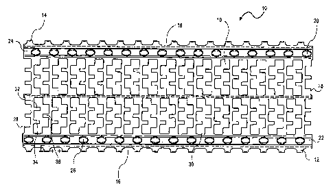
[0013] FIG. 1 is a plan view of a heat exchange splash bar in accordance with
an
embodiment of the present invention.
[0014] FIG. 2 is a sectional, plan view of the heat exchange splash bar
embodiment
depicted in FIG. 1, in accordance with an embodiment of the present invention.
[0015] FIG. 3 is a cross-sectional end view of the heat exchange splash bar
illustrated
in FIG. 1, in accordance with another embodiment of the present invention.
DETAILED DESCRIPTION
[0016] Various preferred embodiments of the present invention provide for an
improved splash bar apparatus and method for use for evaporative heat exchange
processes and
methods. In some arrangements, the heat exchange splash bar apparatus is
utilized in
evaporative cooling towers or the like. It should be understood, however, that
the present
invention is not limited in its application to evaporative cooling towers,
but, for example, can be
used with other systems and/or other processes that require heat exchange.
Preferred
embodiments of the invention will now be further described with reference to
the drawing
figures, in which like reference numerals refer to like parts throughout.
CA 02664574 2009-03-25
WO 2008/039516 PCT/US2007/020855
[0017] Turning now to the drawings, and particularly FIGS. 1-3, a heat
exchange
splash bar, generally designated 10, is depicted in accordance with an
embodiment of the present
invention. The heat exchange splash bar 10 includes a first base flange wall
or portion 12 that
generally lies in a plane A and a second base flange wall or portion 14 that
generally lies in plane
A. As illustrated in the plan view of FIG. 1, each of the first and second
flange walls 12, 14 have
a serrated edge, generally designated 16. As illustrated in FIG. 1, the
serrated edge 16 has a
semi-oval geometry, however the serrated edge 16 may alternatively have
varying geometries
including angled serrations. Referring specifically to FIG. 3, the heat
exchange bar 10 includes
an extension 18, 20, that extends from each of the flange walls 12, 14,
respectively. Each of the
extensions 18, 20 extend from their respective flange walls 12, 14, downward,
away from the
flange walls 12, 14, generally parallel to the longitudinal axis B.
[0018] As depicted in FIGS. 1 and 3, the heat exchange bar 10 includes
opposing first
and second side walls 22, 24 that extend at an angle to the longitudinal axis
B. As illustrated in
detail in FIG. 3, the first side wall 22 extends upwardly away from the first
flange wall 12 at an
angle to the longitudinal axis B. Similarly, as also illustrated in FIG 3, the
second side wall 24
extends upwardly away from the second flange wall 14, at an angle to the
longitudinal axis B in
opposing relationship to the first side wall 22.
[0019] Referring now to FIG. 1, each of the side walls 22, 24 is apertured. As
depicted, each of the side walls 22, 24 is perforated having a series of
apertures, generally
designated 26. While the apertures 26 depicted in FIG. 1 are circular in
geometry, the present
invention includes and provides for apertures 26 of varying shapes and
geometries such as
apertures having elliptical, rectangular, square and/or oval geometries.
[0020] Referring to FIGS. 1-3, the heat exchange splash bar 10 also includes a
top
wall or top portion 28 that extends between the first side wall 22 and the
second side wall 24.
The top wall 28 extends between the first and second side walls 22, 24
generally parallel to plane
6
CA 02664574 2009-03-25
WO 2008/039516 PCT/US2007/020855
A. As illustrated in FIGS. 1 and 2, the top wall 28 is perforated and includes
a plurality of
openings or windows 30. Each of the openings 30 includes a series of finger
portions 32, 34, 36
extending therein.
[0021] Referring .now specifically to FIGS. 1 and 2, the top wall 28 comprises
a
plurality of openings 30, wherein the openings 30 have fingers 32, 34, 36
extending inwardly
into the opening 30. A single opening 30 will be described in detail only as
the openings 30 are
similar in design and geometry. As illustrated in FIGS. 1 and 2, the opening
30 comprises a first
wall, generally designated 38 and an opposing second wall generally designated
40. The first
wall 38 extends between a pair of side walls 42 whereas the second wall 40
extends between a
pair of protrusions 44 that each extend from the side walls 42.
[0022] Fingers 32, 34 extend from the opening 30 side wall 38 generally
parallel to
one another whereas finger 36 extends from side wall 40 in opposing
relationship to fingers 32,
34. As illustrated in the figures, each of the fingers 32 and 34 is generally
square or rectangular
in shape and geometry, however the fingers 32, 34 may alternatively have
circular and round
geometries. As depicted in FIGS. 1 and 2, fingers 32, 34 are positioned
adjacent one another
and extend generally parallel to one another, away from the side wall 38, and
inward into the
opening 30. The fingers 32, 34 also extend generally parallel to the plane A
(as illustrated in
FIG. 3) and normal to the longitudinal axis B (also as illustrated in FIG. 3).
[0023] The finger 36 located and extending for the opposing side wall 40 of
the
opening 30, and like previously described fingers 32, 34, the finger 36 is
generally square or
rectangular in shape and geometry. It, however, may alternatively have
ciicular and round
geometries. Also, like the previously described fingers 32, 34, the finger 36
extends into the
opening 30 from the opposing side wall 40. The finger 36 also extends
generally parallel to the
plane A (as illustrated in FIG. 3) and normal to the longitudinal axis B (also
as illustrated in FIG.
7
CA 02664574 2009-03-25
WO 2008/039516 PCT/US2007/020855
3). As depicted in FIGS. 1 and 2, the finger 36 extends into the opening 30 at
a position
generally between the fingers 32 and 34.
[0024] The heat exchange splash bars illustrated in FIGS. 1-3 may be formed
from
any sort of material that allows for heat exchange such as plastics, metals
and/or synthetic resins
and may have geometries alternative from those illustrated. For example, in
one embodiment of
the present invention, the heat exchange bar 10 may be formed from a synthetic
resin material
such as polyvinylchloride. For example, in another embodiment of the present
invention, the
splash bar 10 may not utilize or employ the serrated base portions 12, 14 and
alternatively utilize
solid edge bases. Moreover, other embodiments of the present invention may not
employ a total
of three fingers 32, 34, 36 that extend into the openings 30. To the contrary,
these embodiments
may utilize a greater number of fingers or a less number.
[0025] The heat exchange bars depicted in FIGS. 1-3 and described above, may
be
used in mechanical draft crossflow cooling towers or the like. The towers
oftentimes include an
upright central plenum with a venturi-type fan stack. The fan stack typically
includes a
mechanically powered fan that is disposed therein. The cooling towers in which
the heat
exchange splash bars are typically used may include water distribution basins
for receiving hot
water to be cooled and distributing the same via an apertured bottom wall
forming a part of each
basin. Alternatively, the cooling towers may employ a water distribution
system which utilizes
spray nozzles to distribute the water to be cooled. The cooling towers also
include a cold water
collection basin which is positioned beneath the water distribution system or
assembly and the
plenum. The cooling tower in which the heat exchange splash bars 10 may be
utilized also
include a grid assembly or similar support structure, which functions to
support a plurality of
heat exchange splash bars, similar to embodiments described above. As
previously discussed,
the heat exchange splash bars serve to break up hot water distributed by the
hot water distribution
system or basin.
8
CA 02664574 2009-03-25
WO 2008/039516 PCT/US2007/020855
[0026] During operation of cooling towers similar to those previously
described
above, hot water is initially delivered to the hot water distribution system
or basins. The hot
water is then distributed onto the heat exchange splash bars which serve to
break up the water
into small droplets. Simultaneously, the fan functions to draw incoming, air
currents into and
through the cooling tower such that the air comes into intersecting, thermal
interchange
relationship with the water droplets. The air proceeds to pass through and
heat exchange splash
bars and then is exhausted to the atmosphere through the fan stack.
[0027] Although the heat exchange splash bars of the present invention are
described
for use with crossflow cooling towers, the present invention is not limited to
crossflow cooling
towers only. Specifically, the heat exchange splash bars described in
accordance with the present
invention may alternatively be utilized with counterflow towers.
[0028] The many features and advantages of the invention are apparent from the
detailed specification, and thus, it is intended by the appended claims to
cover all such features
and advantages of the invention which fall within the true spirit and scope of
the invention.
Further, since numerous modifications and variations will readily occur to
those skilled in the art,
it is not desired to limit the invention to the exact construction and
operation illustrated and
described, and accordingly, all suitable modifications and equivalents may be
resorted to, falling
within the scope of the invention.
9