Note: Descriptions are shown in the official language in which they were submitted.
CA 02664758 2009-03-26
WO 2008/048122 PCT/NZ2007/000312
- 1 -
FLUID RELEASE VALVE USING FLEXIBLE FLUID PERMEABLE
MEMBRANE
The present invention relates to a fluid release device and in particular but
not
solely to an ethylene release device and to related methods for conditioning
plant
material.
BACKGROUND TO THE INVENTION
Ethylene is a well known fruit ripening agent (Kays, S. and Beaudry, R. Acta
Horticulturae 201: 77-115 (1987)). It has been widely used in gas form for
post-
harvest fruit ripening. Ethylene-containing conditioning rooms are used for
ripening fruit and vegetables in bulk.
As well as ethylene per se, a large number of ethylene releasing compounds
have also been used in ripening processes (Kays, S. and Beaudry supra.). These
ethylene releasing compounds generally include a haloethyl group attached to a
sulphur, phosphorus, or silicon atom. Their operation may be pH dependent and
toxic breakdown products may be produced when used. Such compounds are
primarily employed for pre-harvest plant conditioning applications.
Packaging and devices useful in post harvest fruit ripening are also known.
For example, US Patent No. 3,069,274 describes a foam protector for fruit,
impregnated with ethylene halides such as ethylene dichloride for fruit
ripening.
The use of ethylene halides in packaging is contraindicated where they produce
irritating vapours that can blister skin and cause serious pulmonary damage,
corneal
clouding, and liver and kidney damage to people.
US 5,525,130 describes a label device consisting of a two compartment
capsule. The compartments are separated by a rupturable membrane and contain
compositions that when combined release ethylene. For example, (2-chloroethyl)
phosphoric acid and a base. The device is expensive and the compartment
components are known skin and eye irritants.
Capsules containing ethylene gas for fruit ripening are also described in Ma
et
al., Journal of Fruit Quality: 23 (200) 245-259. These are impractical, large
volume,
CA 02664758 2014-12-11
- 2 -
plugged capsules which require plug or cap removal to allow ethylene release
in
packaging. Moreover, gas release is relatively rapid and non-linear.
Accordingly, there is a need for an ethylene release device that is capable of
releasing ethylene without production of undesirable products. There is also a
need for
an ethylene release device that is of a size and type suited to inclusion in
packaging.
There is also a need for an ethylene release device that can appropriately
control the
desired rate of release of ethylene.
Embodiments described herein may provide a fluid release device and related
methods suitable for use in conditioning plant material which addresses at
least one of
the abovementioned limitations, or which may at least provide the public with
a useful
choice.
Embodiments described herein may provide a fluid release device that addresses
at
least some of the abovementioned limitations or which may at least provide the
public
with a useful choice.
SUMMARY OF THE INVENTION
The disclosure may provide a fluid flow control valve, suitable for
controlling the
flow rate of fluid to the surrounding environment from a fluid storage
reservoir that
CA 02664758 2014-12-11
- 3 -
includes a fluid outflow passage for fluid that is at a higher pressure inside
of the
reservoir than the surrounding environment. The fluid flow control valve
includes an
elastic fluid permeable membrane to control the flow of fluid through the
passage, the
membrane including an absorption surface to absorb fluid from the reservoir
into the
membrane, and a desorption surface to desorb fluid from the membrane to the
surrounding environment. The membrane is subjected to pressure proportional to
the
pressure differential between the reservoir and the surrounding environment,
which
causes the membrane to deform to vary the effective fluid flow path between
the
reservoir and the surrounding environment.
The membrane may be configured to passively transition between a more
pressurised condition -where a pressure is applied by the fluid in the
reservoir to the
membrane to bias the membrane against a first flow path restrictor in a manner
to define
an effective fluid flow path through the membrane that is of greater
resistance to the
flow of fluid from the reservoir and a less pressurised condition where a
reduced
pressure is applied by the fluid in the reservoir to the membrane to bias the
membrane
against a second flow path restrictor in a manner to define an effective fluid
flow path
through the membrane that is of a of lower resistance to the flow of fluid
from the
reservoir.
CA 02664758 2014-12-11
- 4 -
The pressure of the fluid in the reservoir may communicate with the membrane
via a piston having a displacement controlled by the pressure differential
between the
reservoir and the surrounding environment.
The effective fluid flow path may be defined by the surface area of the
membrane
available for the absorption of fluid from the fluid reservoir and/or the
surface area of
the membrane available for the desorption of fluid to the surrounding
environment.
In use, a biasing of the membrane may occur to bring the desorptive surface of
the membrane into contact with at least one of the flow path restrictors to
reduce the
effective fluid flow path defined by the orifice.
The fluid flow control valve may provide a substantially linear fluid flow
rate
profile over a substantial portion of time of discharge of fluid from the
reservoir.
The fluid flow control valve may provide a final rapid release of residual
fluid in
the reservoir at a predetermined pressure differential.
The disclosure may provide a fluid release valve suitable for regulating a
flow of
fluid from a fluid reservoir. The fluid release valve includes a body member
including an
inlet, an outlet in fluid communication with the inlet via a flow passage, an
elastic fluid
permeable membrane extending across the flow passage to restrict the flow of
fluid
between the inlet and outlet, and an impermeable flow path restrictor. The
flow path
restrictor and the membrane are
CA 02664758 2014-06-16
- 5 -
configured and adapted operationally to interact with each other to allow the
flow of
fluid along the flow path as a function of the quantity of fluid in the fluid
reservoir.
The valve may include a closure member for closing the flow passage so that no
fluid may flow through the passage.
The membrane may be displaceable between a restricted barrier position in
which
the membrane engages more with the flow path restrictor whereby the fluid
passage is
more restricted, and a less restricted barrier position in which the membrane
is engaged
less with the flow path restrictor whereby the fluid flow passage is less
restricted.
The fluid reservoir may be pressurised in relation to the surrounding
environment
and the membrane and flow path restrictor interact with each other to vary the
effective
flow path through the passage by virtue of the pressurised fluid.
The interaction of the flow path restrictor and the membrane may be such that
the flow path is more restricted when the pressure in the fluid reservoir may
be high, and
the flow path may be less restricted when the pressure in the fluid reservoir
may be
relatively lower.
The flow path restrictor may be located adjacent the membrane to allow a
variable
amount of contact therebetween to vary the permeation of fluid through the
membrane.
CA 02664758 2014-06-16
- 6 -
The flow path restrictor may be disposed either proximal more the inlet of the
passage relative the membrane, the flow path restrictor presented to interact
with the
membrane to influence the absorbtion of fluid into the membrane, or proximal
more the
outlet of the passage relative the membrane to interact with the membrane to
influence
the desorption of fluid from the membrane.
The flow path restrictor and the membrane may be moveable relative to each
other and may come into a variable degree of contact to deform the membrane so
as to
restrict permeation of the fluid through the membrane.
The flow path restrictor may be composed of an inelastically resilient
material.
The membrane may be in the form of a planar film.
The membrane may be a hollow sheath.
The flow path restrictor may be defined by a body having a cavity that may be
in
fluid communication with the surrounding environment and having at least one
opening
to the cavity that may be in fluid communication with the fluid in the
reservoir via the
membrane.
The body may include a hollow cylindrical portion.
CA 02664758 2014-06-16
- 7 -
The membrane may include a hollow sheath configured and dimensioned to fit
snugly around at least part of the hollow cylindrical portion and fluid
pressure may act on
the sheath to bias the sheath against the hollow body having a cavity.
Formed at the cylindrical region may be at least one annular channel into
which
the membrane, under pressure from the fluid may be forced yet be resiliently
biased in a
direction out of the channel.
The cylindrical region may include a plurality of annular channels.
The fluid pressure may act against the sheath's elasticity to encourage the
sheath
to conform to the channel or channels at higher reservoir fluid pressures,
thereby
restricting the flow of fluid through the at least one opening that is in
fluid
communication with the body having a cavity and may retract at least partially
from
contact with the channel or channels at lower pressures thereby reducing the
restriction
on the fluid flow.
The body may include a pressure release passage formed into an outer surface
of
the body and with which a membrane provided as a hollow sheath may interact to
become compliant therewith under higher fluid pressure thereby closing the
passage and
which enables unrestricted fluid communication of the fluid reservoir with the
surrounding environment at a predetermined lower fluid threshold pressure.
CA 02664758 2014-12-11
- 8 -
The disclosure may provide a gas release device including a reservoir of
pressurised gas to be released, a passageway from the reservoir to an outlet,
an elastic gas
permeable membrane in the passageway and/or at the outlet that allows gas
release only
via the membrane to, or from, the outlet, and a gas impermeable member in the
passageway that includes a gas permeable member interface positioned to
contact the gas
permeable membrane. The displacement of the gas permeable membrane is
responsive
to the pressure of the gas in the reservoir such that there is a greater
interfacial contact
between the gas impermeable member and the gas permeable membrane at a higher
gas
pressure than at lower pressure to thereby vary the exposed cross sectional
area of the
permeable membrane available to the flow in an inverse relationship to
pressure.
The gas impermeable member may be rigid.
The disclosure may provide a self contained gas release device that can
release a
gas at a constant flow rate over a period of time. The gas release device
includes a
pressure vessel that contains a gas to be discharged therefrom and a valve for
the
pressure vessel to control the discharge of gas from the pressure vessel. The
valve
includes a body that defines an aperture for discharging gas to pass through
to the
environment surrounding the device. The body also defines a control surface.
The valve
also includes an elastic gas permeable membrane interposing direct gas flow
from the
pressure vessel to the aperture so that gas must permeate through the membrane
in order
to discharge from the pressure vessel. The membrane is located adjacent the
control
CA 02664758 2014-12-11
- 9 -
surface to, at lower gas pressure of the gas, form a passage between the
control surface
and the aperture that is of a greater size than at higher gas pressure where
the membrane
is more compliant to the shape of the control surface by virtue of a higher
gas pressure
biasing the membrane against the control surface.
The membrane may be composed of an elastically resilient material, optionally
such a material may be selected from the group of elastomeric polymers
including
silicone, synthetic hydrocarbons and natural rubber and any combinations
thereof.
The fluid in the fluid reservoir may be a gas or a gas mixture comprising one
or
more of the following ingredients or properties selected from: ethylene,
propylene,
methyl, cyclopropene, pyrethin or synthetic pyrethroids, ethylene oxide methyl
bromide,
pheromones, fumigants, pesticides, carbon dioxide, sulphur dioxide, or
anaesthetic,
propulsion, fragrance, aroma, flavour, or corrosive properties.
The disclosure may provide a self contained gas release device that can
release a
gas at a constant flow rate over a certain period of time. The device includes
a pressure
vessel that contains a gas to be discharged therefrom and a valve for the
pressure vessel
to control the discharge of gas from the pressure vessel. The valve includes a
body that
includes a cylindrical body portion that has at least one circumferential
groove formed
into it. Within the groove there is at least one aperture that makes a fluid
connection
between the groove and the environment surrounding the device for discharging
gas to
pass through. The valve also includes an elastic gas permeable membrane that
is located
CA 02664758 2014-12-11
- 10 -
over the groove to interpose direct gas flow from the pressure vessel to the
aperture so
that gas must permeate through the membrane in order to discharge from the
pressure
vessel, the groove being of a profile to allow variable compliance of the
membrane
against at least part of the groove as a result of variation in pressure of
the gas acting on
the membrane wherein as the gas discharges and the gas pressure in the vessel
decreases,
the membrane releases from the groove to make available more surface area for
the
desorption of gas permeating through the membrane to increase the effective
flow path
for gas, and wherein by virtue of the decrease in pressure the gas discharge
rate can
remain substantially constant over a period of time.
The disclosure may provide a method for conditioning plant material. The
method involves the steps of providing a fluid release valve or the device as
claimed
above that is associated with a pressurised fluid reservoir in an environment
that is at
least partially fluid-tight and that contains plant material and exposing the
plant material
to fluid from the fluid release valve over a time period.
The fluid released by the fluid release valve may be ethylene.
CA 02664758 2014-06-16
- 11 -
The plant material may be retained in the environment with a concentration of
ethylene gas of between about 1 ppm to about 250 ppm for a time period of
between
half a day to 7 days.
In the case of the plant material being pears or bananas, the plant material
may be
retained in the environment with a concentration of ethylene gas maintained
between 100
ppm and 200 ppm for 2 to 5 days.
In this specification, where reference has been made to external sources of
information, including patent specifications and other documents, this is
generally for the
purpose of providing a context for discussing the features of the present
invention.
Unless stated otherwise, reference to such sources of information is not to be
construed,
in any jurisdiction, as an admission that such sources of information are
prior art or form
part of the common general knowledge in the art.
As used herein the term "and/or" means "and" or "or", or both.
As used herein "(s)" following a noun means the plural and/or singular forms
of
the noun.
CA 02664758 2014-06-16
12
The term "comprising" as used in this specification means "consisting at least
in
part of". When interpreting statements in this specification which include
that term, the
features prefaced by that term in each statement all need to be present but
CA 02664758 2014-12-11
- 13 ¨
other features can also be present. Related terms such as "comprise" and
"comprised" are to be interpreted in the same manner.
It is intended that reference to a range of numbers disclosed herein (for
example, 1 to 10) also incorporates reference to all rational numbers within
that
range (for example, 1, 1.1, 2, 3, 3.9, 4, 5, 6, 6.5, 7, 8, 9 and 10) and also
any range of
rational numbers within that range (for example, 2 to 8, 1.5 to 5.5 and 3.1 to
4.7).
The disclosure may be said broadly to consist in the parts, elements and
features referred to or indicated in the specification of the application,
individually
or collectively, and any or all combinations of any two or more of said parts,
elements or features, and where specific integers are mentioned herein which
have
known equivalents in the art to which this invention relates, such known
equivalents
are deemed to be incorporated herein as if individually set forth.
BRIEF DESCRIPTION OF THE DRAWINGS
Embodiments will now be described by way of example only and with
reference to the drawings in which:
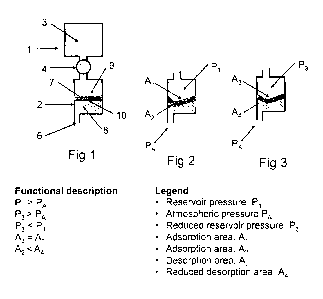
Figure 1 is a simplified cross section of a fluid release device having a
fluid
flow control valve with a dynamic membrane in a less restricted effective
fluid flow
path defining condition,
Figure 2 is a simplified cross section of part of a fluid release device
having a
fluid flow control valve with a dynamic membrane in a more restricted
effective
fluid flow path defining condition,
Figure 3 is a simplified cross section of part of a fluid release device
having a
fluid flow control valve with a dynamic membrane in an intermediately
restricted
effective fluid flow path defining condition,
Figure 4 is a graph of the ethylene gas transmission rate of a range of rubber
and resin membranes, showing the comparatively high rate of silicone,
Figure 5 is a cross-section view of a fluid release device having a fluid flow
control valve with an 0-ring shaped membrane,
Figure 5 b is an end view of the cap in the fluid flow control valve,
CA 02664758 2009-03-26
WO 2008/048122 PCT/NZ2007/000312
- 14 ¨
Figures 6a-c show cross7section views of part of the valve of Figure 5
illustrating the effect of a decreasing pressure differential on the piston
and
membrane,
Figure 7 is a cross-section view of a fluid release device having a fluid flow
control valve with twenty 0-ring shaped membranes connected to a separate
ethylene reservoir,
'Figure 8 is a cross-sectional perspective view of part of the valve of Figure
7,
Figure 9 is a cross section of a fluid release device that includes a "push-
in"
fluid flow control valve,
Figure 9a is a perspective view of a variation of Figure 9,
Figure 9b is a sectioned perspective view of Figure 9a,
Figure 9c illustrates the fluid release device in perspective, in section,
associated with a reservoir,
Figure 9d is a front view of the fluid release device of Figure 9a, showing a
7
groove embodiment,
Figure 9e is a sectional view of the fluid release device shown in Figure 9d,
Figure 10 is a cross section of a fluid release device that includes a "push-
out"
fluid flow control valve,
Figures 11a-c are schematic diagrams of a part of a fluid release device that
is
of a "push-out" or "push-in" type, that show different parts of the membrane
producing different release profiles contributing to a flow linear release
profile,
Figure 12 is a graph of the flow rate of a fluid from a fluid release device
with
a "push-in" fluid flow control valve as the pressure of the fluid within the
device
decreases,
Figure 13 is a graph of the mass data for a fluid release device with a "push-
in" fluid flow control valve during release of ethylene gas,
Figure 14 is a graph of the firmness of pears contained in Euro-boxes and
standard cartons with and without exposure to ethylene released from a fluid
release
device,
Figure 15 is a graph of the effect of concentration of ethylene, achieved by
injecting ethylene into sealed conditioning chambers preloaded with unripe
fruit,
CA 02664758 2009-03-26
WO 2008/048122 PCT/NZ2007/000312
- 15 ¨
and length of conditioning period on firmness and aroma of Green Anjou pears
at
20 C,
Figure 16 is a graph showing the release rate for constant rate discharge for
base units as shown in figure 9A-9E.
DETAILED DESCRIPTION OF THE INVENTION
As used herein the term "storage reservoir" refers to a container, tank,
canister, capsule or similar to hold a pressurised and/or concentrated fluid
that
preferably may be or may include ethylene.
As used herein the term "fluid" refers to a substance capable of flowing and
may include a gas and a gas that may be liquefied. Typical fluids for release
by the
fluid release device may include ethylene, propylene, fumigants such as methyl
bromide and ethylene oxide, insecticides such as pyrethrin and synthetic
pyrethroids, pheromones, corrosive gases such as hydrogen fluoride that would
react with metal components in conventional flow regulators, aroma-releasing
fluids
for medicinal and recreational use, such as menthol and eucalyptus, medicines
and
anaesthetics.
As used herein the term "surrounding environment" refers to the environment
to which the fluid is released from the fluid release device. The environment
may
comprise a ripening container such as a clamshell, pallet or euro-box for
holding a
plant material. Intervening processing of the fluid such as a mixing with
other
substances or other flow control other than that herein described may occur
between the storage reservoir and the surrounding environment.
As used herein the term "absorb" and the related terms "absorption" and
"absorptive" refer to the process wherein atoms, molecules or ions of a fluid
enter
to permeate through a membrane.
As used herein the term "desorb" and the related terms "desorption" and
"desorptive" refer to the process wherein atoms, molecules or ions of a fluid
leave a
membrane, and includes exudation of atoms, molecules or ions of a fluid from a
membrane.
CA 02664758 2014-06-16
16
As used herein the term "membrane" refers to a fluid permeable barrier
provided
to be operative between the fluid reservoir and the surrounding environment.
As will be
understood from the following description the membrane need not be of a film-
like or
planar configuration.
As used herein the term "passively transition" refers to geometrical
adjustment of
the membrane in response to a changing pressure differential.
As shown in Figures 1-3, the fluid release device (1) may generally be said to
include a fluid flow control valve (2) and a fluid storage reservoir (3). More
preferred
forms of the device (1) are described below. Figures 1-3 describe salient
features of the
invention.
The reservoir (3) is a pressure vessel that can store gas (or liquefied gas)
at a
pressure greater than the surrounding atmosphere. In use, the reservoir (3) is
in fluid
communication with the valve (2) but any such fluid communication between the
valve
(2) and reservoir (3) may be disrupted by a flow valve (4). One or more fluid
flow
passages may extend between the reservoir (3) and valve (2). Alternatively the
enclosed
space of the reservoir 3 may in part be defined by part of the valve (2).
The valve (2) includes at least one outlet such as outlet (6) to allow fluid
to be
released from the reservoir (3). Such release may be direct release from the
device (1) to
the surrounding environment or to another reservoir or cavity.
Fluid is released from the reservoir (and on the basis that, if provided, the
flow
valve (4) is open) under the control of the fluid flow control valve (2).
The flow characteristics of fluid through the valve (2) are a factor of the
pressure
differential across the valve.
The fluid flow control valve (2) includes a permeable membrane (7) through
which
gas can permeate. It also includes a flow path restrictor such as a flow path
control
surface 8 for the membrane.
In the embodiment shown, the membrane (7) has at least one first surface that
is
exposed to the fluid on the reservoir side 1. The surface(s) (9) is an
absorption surface
CA 02664758 2014-06-16
17
through which fluid from the reservoir first passes to permeate through the
body of the
membrane.
In this embodiment the membrane (7) also has at least one second surface (10)
that
is in fluid communication with the outlet (6). The surface(s) (10) is a
desorption surface
through which fluid that has permeated through the membrane from the
absorption
surface(s), passes to be discharged through the outlet (6).
In this embodiment the membrane is a dynamic membrane that passively
transitions under influence of a pressure differential between the reservoir
and the
surrounding environment between: (i) a first pressurised differential (A1>A2
Figure 2)
where the valve has a first effective flow path (10) for fluid to pass through
and (ii) a
second pressure differential that is less than the first (A3<A1 Figures 2 and
3) wherein
the valve 2 has a second effective flowpath (10) therethrough that is of a
greater
desorption area (figure 3) than the first (Figure 2) .
This is achieved in this embodiment by the provision of at least one flow path
restrictor such as the surface (8) with which the membrane dynamically
cooperates.
The restrictor changes the effective flowpath size of the valve. A restrictor
may act
on one or both of the absorption surface and desorption surface to change
their effective
free surface area. A change in effective area is directly proportional to the
flowpath size
and hence the flow rate through the membrane.
In Figures 1-3, the desorption surface (10) is presented to in part be able to
press
against the control surface (8.) In the condition shown in Figure 1 the
desorption
surface in fluid communication with the outlet 6 is larger than in Figures 2
and 3. Hence
a higher flowrate can be expected for a given pressure differential across the
valve.
The interaction of the membrane with the control surface(s) is dependent on
the
pressure differential across the valve. As the membrane is a dynamic membrane
and is
located between the higher pressure reservoir side fluid and the lower
pressure and
effectively constant pressure surrounding atmosphere, a change in pressure of
fluid in the
reservoir will change the interaction of the membrane with the restrictor(s).
In the
CA 02664758 2014-06-16
18
configuration shown in Figures 1-3 a drop in pressure differential will at
least partially
release the membrane from the control surface and increase the exposed
desorption
surface area thereby increasing the fluid flowpath area.
The appropriate selection of membrane rigidity, thickness, unloaded shape,
positioning relative to the control surface(s) and the appropriate selection
of control
surface shape can allow the desired fluid release profile over time to be
achieved. This
can be easily modelled using appropriate software tools.
Gas permeation through a membrane may occur due to three factors; the first is
the rate of absorption of the gas onto the surface of the membrane, the second
is the
permeation of the gas through the structure of the polymer, and the third is
the rate of
desorption of the gas off of the surface of the membrane.
In this embodiment the fluid release profile is such that over a period of
time it is
substantially constant. This period of time is preferably a substantial period
of time of
the total duration of release of fluid from the device in use.
Accordingly the dynamic membrane allows for a linear release rate of the fluid
from
the reservoir.
If a constant release rate isn't required, the rigidity, upload shape,
positioning
relative to the control surface shape can be modified to allow whatever fluid
release
profile desired (increasing or decreasing rate).
The fluid flow control valve may be attached to or integral with a reservoir
containing ethylene, thereby providing an ethylene release device for use in
the
conditioning of plant material. In this embodiment the permeable membrane is
comprised of silicone rubber because of the permeability characteristics of
silicone
rubber referred to herein.
Figure 4 is a graph of the ethylene permeability of a range of rubber and
resin
membranes. The tests indicate that transmission rates through silicone
elastomer is
significantly faster than other rubbers (e.g. EVA 190, Natural red rubber).
CA 02664758 2014-12-11
18a
For the fruit ripening application the ethylene transmission rate of the
membrane
may be of the order of 2.5 x 10⁻¹¹ cm3per cm thickness of material per cm-2 s1
Pa (this is
the volume of ethylene that travels through a given membrane thickness in a
certain time
(seconds) under a pressure differential on a given membrane area). A silicone
elastomer
with 30 to 70 shore hardness is a material that meets these requirements.
CA 02664758 2009-03-26
WO 2008/048122 PCT/NZ2007/000312
- 19 ¨
The ethylene release devices of the present invention can be portable and
efficacious and may store the required amount of pure ethylene to ripen fruit
with a
full flavour in conventionally packed fruit in individual cartons (about 0.12
g total
ethylene). These devices containing (2.5 g total ethylene) may be suitable for
in-
transit conditioning, or alternatively may be sealed within a plastic-covered
pallet to
condition fruit "to order" over a 1-5 day period at ambient temperature in
small
batches.
During conditioning, a device may be placed into a carton or covered pallet
and the ethylene is then released at a constant rate over a substantial
portion of the
release time. This encourages the maintaining of for example about 100 ppm
ethylene inside the carton or covered pallet for a specified number of days
depending on requirements. For example, the device of the present invention
can
release 20mg hr-1 of C91-14 to the atmosphere for a period of say 5 ¨ 7 days
to
maintain a concentration of not less than 100ppm in an enclosed volume
corresponding to a pallet of pears wrapped in a polyethylene liner.
Immediately after the required conditioning time, ethylene can automatically
and rapidly be dumped from the device, such as by an avalanche valve that may
be
incorporated in the device.
Some specific embodiments of the device will now be described as examples.
Ethylene Release Device incorporating 0-ring membrane
Figure 5 depicts one embodiment of an ethylene release device 401 in which
the valve includes a dynamic 0-ring shaped membrane 405 and a piston 403
slideably located by a cylindrical bore that may form part of or be in fluid
communication with a fluid reservoir 409. The membrane 405 is sandwiched
between the piston 403 and a lower rim 414 of the valve. The reservoir may be
hermetically closed by a lid 410 fitted into a snaplock groove 411 and sealed
by a
nitrile o-ring 412. The 0-ring creates a gas impermeable seal between 411 and
409
and may be chosen from such materials as nitrile rubber.
Ethylene stored in the reservoir 409 passes through aperture 404 to contact
and be absorbed into the silicone 0-ring membrane 405. The ethylene permeates
CA 02664758 2009-03-26
WO 2008/048122 PCT/NZ2007/000312
- 20 ¨
through the 0-ring membrane 405 and is desorbed from the 0-ring membrane 405
to release into the surrounding environment via the annular vent 408.
When the device is fully loaded with ethylene, the 0-ring membrane 405 is
under compression by the piston and between the piston 403 and the lower rim
414
thereby reducing the absorption surface area and/or desorption surface area of
the
0-ring membrane available to the ethylene. This restricts the rate of release
of
ethylene from the device into the surrounding environment.
As the ethylene is released, the internal pressure in the reservoir 409
decreases.
The pressure exerted via the piston 403 on the 0-ring 405 will decrease,
permitting
the compressed 0-ring membrane to expand and force the piston 403 upwards.
This increases the absorption surface area and/or desorption surface area of
the 0-
ring membrane 405 available to the ethylene. This enhances the rate of release
of
ethylene from the device into the surrounding environment and compensates for
the expected reduction in ethylene release rate as ethylene is released and
the
internal pressure drops, in order to maintain a constant overall fluid release
rate.
Figures 6a-c show a silicone rubber 0-ring membrane within an ethylene
release device. Figures 6a-c illustrate the shape changes of the 0-ring
membrane as
the internal pressure decreases.
When the device is fully loaded with ethylene at say 8 bar (stage 1 in Figure
6a), the compressed 0-ring membrane completely fills the surrounding cavity
and
seals on all four walls of the housing as well as the cross vent. In this
configuration,
ethylene 612 passes between the inside reservoir wall and the piston,
permeates
through the compressed silicone 0-ring membrane and desorbs from the
desorption surface 610 of the membrane and is released through the cross vent
groove 407 between the reservoir and piston.
As ethylene is released, the piston moves upwards and the 0-ring membrane
becomes more circular and retracts from some or-all four corners of the
housing.
This exposes a progressively larger surface area of 0-ring membrane to the
ethylene
in the reservoir. The resulting enhanced absorption of ethylene from the
reservoir
into the 0-ring membrane and an increased surface area for desorption 610
CA 02664758 2014-12-11
- 21 ¨
compensate for the falling pressure of ethylene in the reservoir, so that the
rate of
ethylene release through the 0-ring membrane may remain constant.
The pressure over which control is exercised can be modified as illustrated by
the vertical groove 415 in 403 (Figure 5). The nitrile 0-ring 412 created an
airtight
seal between 411 and 409.
At about 2-3 bar internal gas pressure (Figure 6b), the 0-ring membrane may
retract from the cross vent groove 407 and the ethylene that has accumulated
in the
inner/upper piston cavity escapes to atmosphere. This exposes a larger
desorption
surface 610 of the membrane to the surrounding environment and also creates a
shorter path for ethylene release through the 0-ring membrane.
As the gas pressure continues to decrease (Figure 6c), the 0-ring membrane
may retract from both side walls of the cavity to provide further shorter
pathways
for ethylene escape through the 0-ring membrane.
An Ethylene dump safety mechanism is provided by the top and/or bottom
and/or side(s) of the 0-ring disengaging the housing and releasing any
residual
ethylene. This mechanism:
(i) May ensure safe disposal of potentially explosive ethylene gas,
(ii) May control the length of the conditioning period, and
(iii) May reduce the potential for on-going collateral damage to nearby fruit.
For gas-dumping to occur effectively, rapid release of the residual ethylene
from the reservoir is needed.
This mechanism occurs at about 1 bar internal pressure, the seals on the top
and bottom of the 0-ring membrane may be released and residual ethylene
rapidly
and completely empties from the reservoir.
Ethylene release devices of the present invention may comprise a plurality of
0-ring membranes 703, each 0-ring membrane is sandwiched between spacing
members 705 as depicted in Figure 8. By increasing the number of 0-ring
membranes the release rate of ethylene may be changed. The flow path for the
ethylene is downwards through a gap 701 between the inner surface of the
cylindrical bore 709 and the spacer members 705 , between upper and lower
surfaces of the spacer members 705 then permeates through the 0-ring membranes
CA 02664758 2009-03-26
WO 2008/048122 PCT/NZ2007/000312
-22-
703 and through the gap between spacer members 705 exiting through the central
passage 713. The nitrile o-ring 710 seals the gap between the body 714 and the
outer wall 709. The same principle of operation applies between end members
606,
609 and adjacent spacer members 605.
The valve shown in Figure 7 is suitable for attaching to a pressurised capsule
603 via connector 601. Alternatively the valve may be integral with the
ethylene
storage reservoir.
Ethylene Release Device incorporating sleeve membrane
Figure 9 depicts another preferred embodiment of an ethylene release device
180 in which the valve includes a dynamic silicone rubber sleeve membrane 183.
One end of the sleeve membrane 183 may be closed, although preferably both
ends
of the sleeve membrane 183 are open. In a first configuration the sleeve
membrane
is arranged in a "push-in" configuration. The valve includes a hollow cylinder
185
having an internal bore 189. The cylinder 185 is fitted inside a silicone
rubber sleeve
183. The ethylene gas 182 permeates inwardly through the silicone then passes
through an orifice 187 into the hollow interior bore 189 of the cylinder 185
that is
vented to atmosphere.
The valve is designed with one or more circumferential grooves 184 to
implement the geometric effect described above. The compliance of the silicone
rubber sleeve 183 allows it to form to the shape of the groove 184 under the
influence of a pressure differential. The surface of the groove 184 in contact
with
the silicone sleeve 183 acts as a flow path restrictor and inhibits desorption
of gas
from the surface of the silicone sleeve. Additionally or alternatively the
edges of
the orifices 187 may also implement the geometric effect described above.
The pressure differential is created by the difference between the pressure
within the reservoir and the atmospheric pressure. As ethylene is released
from the
silicone rubber sleeve 183 the pressure decreases, and the elastic properties
of the
silicone rubber sleeve 183 begin to overcome the pressure differential so that
the
silicone begins to pull away from the internal surface of the bore 185, thus
exposing
CA 02664758 2009-03-26
WO 2008/048122 PCT/NZ2007/000312
- 23 ¨
a greater surface area of the sleeve membrane for desorption of gas and hence
at
least partially overcoming the decreasing pressure differential.
With reference to Figures 9A-9E there is shown a variation of the valve of the
present invention. This valve is like the "push-in" valve of Figure 9 and
includes a
cylindrical body 400 that may be located within a pressure vessel 410 as shown
in
Figure 9C. The body includes a cylindrical outer surface 411 about which an
elastic
sleeve such as a silicone rubber sleeve (shown in phantom) can locate in a
snug
manner. The body includes a cavity 412 that can be positioned to be in direct
or
indirect fluid communication with an outlet of or with opening 413 of the
pressure
vessel 410 or directly to the exterior of the ethylene release device 483. The
cylindrical body includes at least one and preferably a plurality of grooves
484 that
are spaced apart in an axial direction along the body 400. The grooves are all
covered by the silicone sleeve. Each of the grooves is in fluid connection
with the
cavity 412. Such fluid connection is preferably provided by at least one
aperture 419
between the cavity 412 and a respective groove. Each groove may be part
circular
or U-shaped in cross-section as shown in Figures 9D and 9E or may be V-shaped
in
cross-section or other non-circular shape. The grooves are each of a profile
to allow
for the silicone membrane to be compliant to the curve of the groove. Under
high
pressure differential the silicone sleeve will be fully compliant with the
profile of
each of the grooves. Under such high pressure gas permeates through the
silicone
membrane only at the aperture 419 of each groove. As the pressure reduces and
the
silicone sleeve pulls away from contacting some of the surface of each of the
grooves, additional desorption surface area becomes available for the passage
of gas
through the silicone sleeve. The depth and width of the grooves may be
formulated
so that the membrane would experience sufficient normal pressure at the
maximum
envisaged operating pressure to ensure that the initial release rate would be
determined by the exposed membrane over the aperture of each groove. A wider
groove may result in a region of the membrane at the centre of the
circumferential
groove that may not lift off until very low pressures. A groove that is too
narrow
may result in the groove from becoming blocked eg., with a membrane of 0.8mm
thick, the membrane in the groove channel could, if sufficiently deep, require
a
CA 02664758 2009-03-26
WO 2008/048122 PCT/NZ2007/000312
- 24 ¨
channel of at least 1.6mm in width otherwise the membrane may interfere with
itself.
For performance of the device, work needs to be extracted from the
membrane by it becoming initially stretched under pressure from the gas in the
reservoir. The membrane then carries potential energy under such a loaded
condition. The membrane material, under high pressure, is forced into each
groove
under pressure where it becomes compliant with the shape of the groove. The
elasticity of the material aids in its return to a non-contact position as the
pressure
decreases. The return force may be increased by increasing the deformation of
the
membrane. Practically, this may be achieved by increasing the depth of the
grooves.
A limit to this arises from the fact that the membrane is being stretched
axially to
accommodate the extra distance to the groove surface, but it is concurrently
being
forced to assume a smaller circumference than the natural, un-stretched
circumference of the membrane sleeve. Therefore a very deep groove can result
in
undesirable wrinkling effects on the membrane when an isostatic pressure is
applied
forcing it to form the geometry of the underlying body.
The entrance of each aperture may be modified to prevent, under high
pressures, the silicone from plugging into the aperture, if this may occur and
if this
may provide an undesirable release profile. Such modification may include the
positioning of a highly permeable but rigid or semi-rigid body at the entrance
to the
aperture 419. Preferably the apertures are of a size to substantially extend
the width
of the groove. If the aperture is of insufficient width compared to the
groove, the
membrane may form a plug into the aperture and may remain there even whilst
other parts of the membrane are lifting off the groove surface.
By changing the number of grooves or the diameter of the body, different
release rates can be achieved. The overall release rate is easily programmed
by
simply duplicating the base unit of a single groove. Figure 16 shows the
results for
1, 2, 4 and 7 unit devices.
The body may be approximately 36mm in overall length and approximately
19mm in diameter. The grooves may be of a width of approximately 1.8mm and
approximately 0.6mm deep. Each aperture may be up to 1.7 mm in diameter. The
CA 02664758 2009-03-26
WO 2008/048122 PCT/NZ2007/000312
- 25 ¨
silicone sleeve that may be used may be approximately 0.8nam thick. The pitch
between the grooves may be 3mm.
The valve shown in Figures 9A-9C also includes an avalanche valve defined by
a slot. The avalanche slot 436 is preferably also covered by the silicone
sleeve
(AdvantalPure: APST-0750-0813P) The avalanche slot can create a fluid
connection
between the interior of the pressure vessel 410 and the cavity 412 via the end
most
groove 440 and its associated aperture. The avalanche valve is formed by the
shallow slot 436 that is cut from, the end extremity of the cylindrical body
400 to the
closest groove. This provides a direct route for venting the gas within the
pressure
vessel to the outside atmosphere when a threshold pressure level is reached
with
depressing pressure within the pressure vessel.
This groove is of a shape to allow compliance of the silicone membrane with
the groove. The silicone membrane remains compliant with the shape of the
groove to close passage of fluid through the groove from the containment
region
414 of the pressure vessel 410 to the cavity 412 until close to the end of the
discharge of the gas from the pressure vessel. The ethylene is discharged from
the
cavity through puncturing of the cap 413 or through a valve fitted to the cap.
Not
until a substantial amount of the gas has been discharged, will the silicone
displace
from the surface of the groove to thereby create a direct passage for gas to
be
released from the containment region.
With reference to Figure 9c it can be seen that the valve of the present
invention may be accommodated within a pressure vessel 410. The valve may in
fact be accommodated within a standard aerosol can and may be inserted through
a
standard opening of aerosol can. This can provide the benefit that the valve
is
provided in a protected environment within the aerosol can and is therefore
protected from any damage that it may otherwise sustain if thrown into a
container
for operation for a period of days.
Figure 10 depicts a "push-out" configuration ethylene release device 190 in
which a valve 196 having an internal dynamic silicone rubber sleeve membrane
193
is attached to a gas reservoir 191. .The device operates in a similar fashion
to the
device depicted in figure 9. The ethylene 192 flows from the reservoir 191
into the
CA 02664758 2009-03-26
WO 2008/048122 PCT/NZ2007/000312
- 76 ¨
valve 196 where it permeates through the silicone membrane 193 and is released
through apertures 197. A higher pressure inside the device than outside the
device
biases the sleeve membrane against the flow path restrictor 195. The flow path
restrictor 195 has grooves 194 to implement the geometric effect described
above.
As the ethylene is released the pressure differential across the membrane
decreases
and the sleeve retracts from the flow path restrictor 195 exposing a greater
surface
area of the sleeve membrane for desorption of gas and hence at least partially
overcoming the decreasing pressure differential.
Without being limited to any particular theory, it is believed that two stages
predominantly control the ethylene release rate. These can be broadly
categorised
into effects as a result of high and of intermediate pressure ranges.
At the initial high pressures, the dominating contribution to gas permeation
is
the pressure driven diffusion across the membrane to the desorption area
available
in the exposed slot area. This area is fixed, and as such, can be described as
an
exponentially decreasing permeation rate.
As the silicone elastomer begins to pull away from the surface as the pressure
decreases, a second effect takes place whereby an extra desorption surface
area
becomes available in the ever widening cavity between the silicone and the
groove.
Once this cavity has a path to the atmosphere via the slot, then the overall
gas flow
is augmented by this secondary contribution.
The flow rate is linearised by ensuring that the increase in desorption
surface
area is sufficient to overcome the reduction in permeation due to the reduced
pressure differential. The maximum extra desorption area is fixed by the
circumference of the silicone sleeve and is essentially limited to the area of
the
groove.
For a given silicone sleeve thickness and initial gas pressure, the desired
release
rate (for example 20 mg hr-1) is simply a function of the slot area. To permit
this
release rate to be linear however requires a final desorption surface area
such that
the release rate at the final decreased pressure gradient substantially equals
the initial
release rate. This desired characteristic is not achieved by simply increasing
the slot
length, as the silicone compliance is not scaled similarly, and to do so would
require
CA 02664758 2009-03-26
WO 2008/048122 PCT/NZ2007/000312
- 27 ¨
a thicker tubing wall, which would subsequently lead to a reduction in
diffusion rate,
this being contrary to the main objective.
The desired release characteristics can be obtained by scaling the diameter of
the tubing used, for example an increase in tubing diameter leads to a greater
circumference which means a greater surface area for desorption and increased
rate
as the pressure decreases through the intermediates range.
Figure 11 is a schematic diagram of a push-in valve illustrating the theorised
mechanism by which a desired release rate is obtained. A flow path restrictor
114
has a groove 118 so that the desorption area increases at an increasing rate
as the
pressure decreases. Additionally a vent hole (not shown) passing through the
flow
path restrictor 114 may be incorporated so that when the silicone sleeve has
relaxed
back to its unstressed position at sufficiently low pressure, then a
perforation in the
silicone is activated so that the residual gas pressure can be vented to the
atmosphere in a short time span to reduce the possibility of unwanted ethylene
release beyond the desired release time.
Figure 11a depicts the valve in a high pressure condition where the release of
ethylene is driven by pressure diffusion through the slot 115. The membrane
116 is
biased against the flow path restrictor 114 to define a small desorption
surface area
110 for release of ethylene to the surrounding environment.
Figure 11 b depicts the valve in an intermediate pressure condition where the
membrane 116 has partially retracted from the flow path restrictor 114 to
reveal a
larger desorption surface area 110 for release of ethylene release to the
surrounding
environment.
Figure 11c depicts the valve in a low pressure condition where the membrane
116 has further retracted from the flow path restrictor 114 to reveal a larger
desorption surface area 110 for release of ethylene release to the surrounding
environment.
The number and/or size of the slots in the valve and/or the thickness and/or
surface area of the membrane can be varied according to the desired gas
release
L
profile. By increasing the number of slots or the size of the slots the
release rate of
the gas is increased.
CA 02664758 2014-12-11
- 28 ¨
Figure 12 shows the substantially linear release rate of ethylene from a "push-
in" fluid release device of Figure 9 as the pressure inside the device
decreases. At
about 1 bar pressure a sudden and complete release of ethylene ("avalanche
release") from the device into the environment is observed.
Figure 13 shows decreasing mass of a "push-in" fluid release device of Figure
9 over time a ethylene is released. The mass linearly decreases for
approximately 7.5
hours. The sudden drop in mass at about 7.5 hours corresponds to the avalanche
release of ethylene observed in Figure 12.
Figure 14 shows the effects on firmness of an exposure of pears to a 5 day
ethylene conditioning treatment. Fruit in mixed pallets of double layer Euro-
packs
and standard cartons where sealed inside a 80 lam plastic film. Ethylene
release
devices configured to release ethylene over a 5 day period where placed inside
a first
sealed pallet. A second sealed pallet was a control and had no ethylene
release
devices included. The flesh of the fruit exposed to the ethylene release
devices
softened and ripened significantly while the control fruit displayed minimal
ripening.
The device may also employ shaping of both the impermeable substrate and
permeable membrane together. In other words, the membrane, as for example used
with reference to the device in Figures 9a ¨ 9e, may not be cylindrical but
could be
flat and the surface features that control the flow rate by virtue of the
elastic
properties, may be on either or both of the membrane and/or the impermeable
substrate.
An advantage of controlled release gas device as per the present invention,
compared to uncontrolled release systems may come into effect when, a) the
minimum active gas concentration for a prolonged time is required to achieve
effectiveness, b) the active gas concentration spontaneously declines
significantly
with time, perhaps due to absorption in produce, or due to auto-oxidation, c)
excessive levels of active gas damage the produce (eg. that simply putting in
high
levels of gas at the start of a treatment is unacceptable). The device may
have the
advantage of being self-contained and that it can be placed inside a container
with
no further access required. The avalanche release feature, if incorporated,
may
ensure that the high contents of the pressure vessel are discharged
CA 02664758 2014-12-11
29
so that when the device is disposed of, no dangerous levels of gas remain
present within
the pressure vessel.
INDUSTRIAL APPLICATION
The system, apparatus and method described herein may be used to condition
plant
material such as fruit or vegetables by releasing ethylene in an environment
in which the
fruit or vegetables are contained. Examples of typical environments occur
throughout
the processing chain of plant materials from harvest to the end consumer and
include
clamshells, euro-boxes and bushel boxes, pallet load of boxes or container
loads of
pallets. Typically these environments will be shrouded with a conventional
perforated
apple box liner or a disposable plastic pallet cover to substantially contain
the ethylene
about the plant material.
The device described herein may be disposable and may be manufactured at low
cost.
Where in the foregoing description reference has been made to elements or
integers having known equivalents, then such equivalents are included as if
they were
individually set forth.
While specific embodiments of the invention have been described and
illustrated,
such embodiments should be considered illustrative of the invention only and
not as
limiting the invention as construed in accordance with the accompanying
claims. For
example the method of and capsules for ripening plant material can include
traditional
mechanical valves controlled manually or electronically.
While the use of valves has been described with respect to plant conditioning,
it
will be appreciated that the valves can be used in a wide variety of
situations where the
flow of a fluid is to be controlled, for example gas tanks for releasing
insecticides,
fumigants or fragrances at a constant rate.
In addition, where features or aspects of the embodiments are described in
terms
of Markush groups, those skilled in the art will recognise that the
embodiments are also
thereby described in terms of any individual member or subgroup of members of
the
Markush group.